EP0162218A2 - Apparatus for dimensioning slide fastener coupling elements - Google Patents
Apparatus for dimensioning slide fastener coupling elements Download PDFInfo
- Publication number
- EP0162218A2 EP0162218A2 EP85103019A EP85103019A EP0162218A2 EP 0162218 A2 EP0162218 A2 EP 0162218A2 EP 85103019 A EP85103019 A EP 85103019A EP 85103019 A EP85103019 A EP 85103019A EP 0162218 A2 EP0162218 A2 EP 0162218A2
- Authority
- EP
- European Patent Office
- Prior art keywords
- presser
- coupling elements
- roll
- shaft
- disk
- Prior art date
- Legal status (The legal status is an assumption and is not a legal conclusion. Google has not performed a legal analysis and makes no representation as to the accuracy of the status listed.)
- Granted
Links
Images


Classifications
-
- A—HUMAN NECESSITIES
- A44—HABERDASHERY; JEWELLERY
- A44B—BUTTONS, PINS, BUCKLES, SLIDE FASTENERS, OR THE LIKE
- A44B19/00—Slide fasteners
- A44B19/02—Slide fasteners with a series of separate interlocking members secured to each stringer tape
-
- B—PERFORMING OPERATIONS; TRANSPORTING
- B29—WORKING OF PLASTICS; WORKING OF SUBSTANCES IN A PLASTIC STATE IN GENERAL
- B29D—PRODUCING PARTICULAR ARTICLES FROM PLASTICS OR FROM SUBSTANCES IN A PLASTIC STATE
- B29D5/00—Producing elements of slide fasteners; Combined making and attaching of elements of slide fasteners
-
- Y—GENERAL TAGGING OF NEW TECHNOLOGICAL DEVELOPMENTS; GENERAL TAGGING OF CROSS-SECTIONAL TECHNOLOGIES SPANNING OVER SEVERAL SECTIONS OF THE IPC; TECHNICAL SUBJECTS COVERED BY FORMER USPC CROSS-REFERENCE ART COLLECTIONS [XRACs] AND DIGESTS
- Y10—TECHNICAL SUBJECTS COVERED BY FORMER USPC
- Y10S—TECHNICAL SUBJECTS COVERED BY FORMER USPC CROSS-REFERENCE ART COLLECTIONS [XRACs] AND DIGESTS
- Y10S425/00—Plastic article or earthenware shaping or treating: apparatus
- Y10S425/034—Morin
-
- Y—GENERAL TAGGING OF NEW TECHNOLOGICAL DEVELOPMENTS; GENERAL TAGGING OF CROSS-SECTIONAL TECHNOLOGIES SPANNING OVER SEVERAL SECTIONS OF THE IPC; TECHNICAL SUBJECTS COVERED BY FORMER USPC CROSS-REFERENCE ART COLLECTIONS [XRACs] AND DIGESTS
- Y10—TECHNICAL SUBJECTS COVERED BY FORMER USPC
- Y10S—TECHNICAL SUBJECTS COVERED BY FORMER USPC CROSS-REFERENCE ART COLLECTIONS [XRACs] AND DIGESTS
- Y10S425/00—Plastic article or earthenware shaping or treating: apparatus
- Y10S425/814—Zipper
Definitions
- the present invention relates to an apparatus for dimensioning individual slide fastener coupling elements of synthetic resin or metal.
- One known dimensioning apparatus includes a pair of presser rolls as disclosed in Japanese Patent Publication No. 42-1939, published January 28, 1967.
- U.S. Patent No. 4,406,849, patented September 27, 1983 shows another dimensioning apparatus which has a presser wheel and a presser die. The presser rolls or the presser wheel is driven through a train of ordinary gears such as spur gears or bevel gears.
- the present invention seeks to provide an apparatus for dimensioning slide fastener coupling elements, the apparatus having positionally adjustable roll means for accurately shaping the coupling elements to desired dimensions such as a width and a length.
- the present invention further seeks to provide an apparatus for dimensioning slide fastener coupling elements, the apparatus having positionally adjustable presser rolls smoothly rotatable in synchronism, while engaging the coupling elements, for dimensioning the coupling elements without scratching or otherwise damaging them.
- the present invention further seeks to provide a coupling element dimensioning apparatus including dimensioning rollers having means for preventing coupling elements legs from being positionally displaced to keep the legs spaced apart at desired intervals or pitches.
- an apparatus for dimensioning slide fastener coupling elements comprising: a base; a pair of first and second shafts rotatably mounted on said base and extending in a common plane and transversely to each other; a first presser roll rotatably supported on said first shaft and having a circumferential wall of a substantially L-shaped cross section composed of a first presser surface lying transversely to said first shaft and a circumferential surface lying parallel to said first shaft and comprising a spur gear; a second presser roll rotatably mounted on said second shaft and having a circumferential surface serving as a second presser surface parallel to said second shaft and confronting said first presser surface, and an end surface parallel to said first shaft and having a pin gear facing said first shaft and held in mesh with said spur gear; said first and second presser surfaces having closest confronting portions for positioning the coupling elements therebetween, said closest confronting portions being spaced from each other by a first distance equal to the thickness of each of the coupling elements between outer surfaces
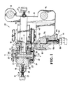
- the dimensioning apparatus 10 is shown as coupled to an apparatus 11 for forming slide fastener coupling elements of synthetic resin.
- the dimensioning apparatus 10 includes two units 10A, 10B disposed at a discharge end of the apparatus 11 along a discharge path for the formed coupling elements.
- the dimensioning apparatus 10 may have only one unit if the formed coupling elements have no tendency to spring back after they have been shaped to the required dimensions.
- the apparatus 11 for forming slide fastener coupling elements has a frame 12 ( Figure 2) on which there are mounted support rods 13, 14 connected to an arm 15. To the arm 15, there is fixed a bracket or base 16 on which a first horizontal shaft 17 is rotatably supported. A first presser roll 18 is rotatably mounted by a pair of roller bearings 19 on the first shaft 17.
- a second vertical shaft 20 is rotatably mounted on a slide block 21 by a pair of ball bearings 23, the second vertical shaft 20 being covered with a sleeve 22.
- the slide block 21 is mounted on the bracket 16 for sliding movement in the axial direction of the first horizontal shaft 17.
- the first horizontal and second vertical shafts 17, 20 extend in a common plane and have respective central axes X - X, Y - Y extending perpendicularly to each other.
- a second presser roll 24 is fixed to an axial end of the second vertical shaft 20 by means of a bolt 25 with a washer 26 interposed between the bolt 25 and the second presser roll 24.
- a screw rod 27 rotatably mounted on the slide block 21 is threaded in an internally threaded hole 28 defined in the bracket 16, the screw rod 27 having an axis parallel to the first horizontal shaft 19.
- the screw rod 27 can be fixed in position with respect to the bracket 16 by a lock nut 29.
- the first presser roll 18 comprises a first disk or wheel 30 and a second disk or wheel 31 that are concentrically fastened together by a pair of bolts 32.
- the first presser roll 18 has an annular recess 33 in an entire circumferential edge thereof facing the second vertical shaft 20.
- the annular recess 33 is defined by an annular step formed by a cross-sectionally L-shaped wall of the first disk 30 and the second disk 31, the second disk 31 being smaller in diameter than the first disk 30.
- the first disk 30 has an annular end face 34 serving as a first presser surface lying perpendicularly to the first horizontal shaft 17.
- the second disk 31 has a circumferential surface lying parallel to the first horizontal shaft 17 and shaped as a spur gear 35 composed of gear teeth each having a trapezoidal cross section.
- the first presser roll 18 also includes a third disk or wheel 31' attached by the bolts 32 to the first disk 30 remotely from the second disk 31.
- the third disk 35 is of an identical structure to that of the second disk 31. Therefore, the first presser roll 18 has two annular recesses 33 on its axially opposite sides.
- the second presser roll 24 is composed of a fourth disk or wheel 36 and a fifth disk or wheel 37 connected concentrically to each other by a plurality of bolts 38.
- the second presser roll 24 has a circumferential surface 39 serving as a second presser surface lying in confronting relation to the first presser surface 34 of the first presser disk 18.
- the second presser roll 24, or the fourth disk 36 thereof has an end face 40 facing the first horizontal shaft 17 parallel thereto and an outer peripheral marginal edge constructed as a pin gear 41 composed of pin teeth 42 each having a frustoconical shape and projecting parallel to the second vertical shaft 20.
- the pin gear 41 is held in mesh with the spur gear 35.
- a third presser roll 43 is rotatably supported on the bracket 16 in horizontally spaced relation to the second presser roll 24, the third presser roller 43 being identical in construction to the second presser roll 24.
- the third presser roller 43 has a circumferential surface confronting the other recess 33 in the first presser roll 18 and a pin gear meshing with another spur gear 44 of the first presser roll 18, as shown in Figure 1.
- the third presser roller 43 is movable in the directions of the arrows C, D by means of a screw rod 45.
- the first, second, and third presser rollers 18, 24, 43 operate in synchronism for processing two rows of slide fastener coupling elements simultaneously to dimension them, as described later on.
- annular array of partition ridges 47 spaced at equal intervals projects from the first presser surface 34 into the recess 33, and another annular array of partition ridges 48 spaced at equal intervals projects from the second presser surface 39 toward the partition ridges 47.
- a bearing ring 49 having an outer circumferential surface serving as a third presser surface 50 extending along the partition ridges 47 perpendicularly to the first and second presser surfaces 34, 49.
- a fourth presser roll 51 is rotatably supported by a third horizontal shaft 52 and has a pair of axially spaced circumferential surfaces or fourth presser surfaces 53 each disposed adjacent to the first, second, and third presser surfaces 34, 39, 50.
- the third horizontal shaft 52 extends substantially parallel to the first horizontal shaft 17 and is supported on a slide block 54 slidably supported on a bracket 55 fixed to the support rod 14.
- the slide block 54 is slidable in the axial direction of the second vertical shaft 20 by a screw rod 56 threaded in an internally threaded hole 57 defined in the bracket 55.
- the slide block 54 and hence the third horizontal shaft 52 are therefore movable in the directions of the arrow G, H by turning the screw rod 56, which can thereafter be locked against rotation by a lock nut 59.
- the first, second, third, and fourth presser rolls 18, 24, 43, 51 are not positively driven, but are caused to rotate by two rows of slide fastener coupling elements 62 ( Figure 2) which are successively formed by the apparatus 11 and discharged by a withdrawal device 61 through the units 10A, 10B.
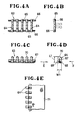
- FIGs 4A through 4E show one form of slide fastener coupling elements which can be dimensioned by the dimensioning apparatus of the present invention.
- a coupling element assembly 63 comprises a plurality of parallel continuous coupling elements 64 of synthetic resin interconnected by connectors 65 in a zigzag configuration, the coupling elements 64 being also connected by a pair of connecting cords 66.
- the coupling element assembly 63 is bent into a cross-sectionally U-shape as indicated by the two-dot-and-dash lines in Figure 4B, and combined with a core cord 67 inserted between legs 68, 69 of each of the coupling elements 64, as illustrated in Figures 4C and 4D.
- the legs 68, 69 of the coupling element 64 are interconnected by a coupling head 70.
- the formed coupling element 64 has a thickness W l between outer surfaces of the legs 68, 69 and a length L l between an end of the coupling head 70 and ends of the legs 68, 69.
- the thickness Wl and the length L l are controlled by the dimensioning apparatus 10 of the present invention.
- the coupling elements 64 dimensioned properly by the dimensioning apparatus 10 are woven into a longitudinal edge of a slide fastener stringer tape 71, as shown in Figure 4E.
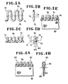
- FIGs 5A through 5E illustrate another form of slide fastener coupling elements.
- a coupling element assembly 72 is composed of continuous coupling elements 74 of synthetic resin having a meandering or zigzag pattern, the coupling elements 74 being interconnected by connectors 75.
- the coupling element assembly 72 is bent about a longitudinal central axis into a U-shaped cross section as indicated by the two-dot-and-dash lines in Figure SB.
- Each of the bent coupling elements 74 has a pair of leas 7 6, 77 interconnected by a coupling head 78 as sham in Figures 5C and 5D.
- the coupling element 74 has illustrated dimensions, that is, thicknesses W2, W3 and a length L2, controlled by the dimensioning apparatus of the invention.
- the dimensioned coupling elements 74 are sewn by sewing threads 79 to a slide fastener stringer tape 80 along a longitudinal edge thereof.
- Figures 6A and 6B show an assembly 82 of discrete slide fastener coupling elements 83 of metal mounted by staking on a reinforcing cord 84 on a longitudinal edge of a slide fastener stringer tape 85.
- the dimensioning apparatus of the invention controlls a thickness W4 of the coupling elements 83.
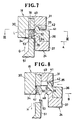
- the first and second presser rolls 18, 24 serve to press the legs of the coupling elements with the first and second presser surfaces 34, 39 to achieve the prescribed widths Wl, W2, W3, W4.
- the first and second presser surfaces 34, 39 therefore have closest confronting portions spaced apart from each other by a distance W equal to one of the widths Wl, W2, W3, W4,' as illustrated in Figure 7.
- the third and fourth presser surfaces 50, 53 have closest confronting portions spaced apart from each other by a distance L which is equalized to one of the lengths Ll, L2 of the coupling elements.
- the dimensioning apparatus 10 can process two rows of such coupling elements 64 to dimension the same simultaneously. Since the two rows of the coupling elements are dimensioned in the same manner, however, the processing of only one row of the coupling elements will be described in detail.
- the screw rods 27, 5 6 are turned about their own axes to slide the slide blocks 21, 54 and hence the second and third shafts 20, 5 2 in the directions of the arrows B, H, respectively.
- the second and fourth presser rolls 24, 51 are moved from the positions of Figures 1 and 7 away from the first presser roll 18 into the positions indicated by the two-dot-and-dash lines in Figure 1 or the positions of Figure 8, in which the first, second, third, and fourth presser surfaces 34, 39, 50, 53 are spaced from each other at increased distances.
- the row of the coupling elements 64 is then inserted between the first, second, thrrd, and fourth presser surfaces 34, 39, 50, 53.
- the coupling elements 64 as they move through the first, second, and fourth presser rolls 18, 24, 51, are pressed by the first through fourth presser surfaces 34, 39, 50, 53 to the prescribed dimensions Wl, Ll.
- the partition ridges 47, 48 mesh with the coupling elements 64 ( Figure 9) to prevent the legs 68, 69 from being positionally displaced under forces applied in the directions of the arrows E, F ( Figure 4D), so that the legs 68, 69 will be spaced accurately at equal intervals or pitches.
- the coupling heads 70 are held against the third presser surface 50 while the ends of the legs 68, 69 are held against the fourth surface 53.
- the legs 68, 69 are prevented by the third and fourth presser surfaces 50, 53 from being longitudinally displaced in position under the forces imposed in the directions of the arrows E, F.
- the first and second presser surfaces 34, 39 are also rotated in synchronism. Therefore, the pressed surfaces of the coupling elements 64 are not subjected to undesired scratches or damages which would otherwise result from asynchronous rotation of the first and second presser surfaces 34, 39.
- the meshing engagement between the spur gear 35 and the pin gear 41 permits them to remain uniformly intermeshed without wobbling or forced meshing engagement even when the second presser roll 24 is axially displaced in the directions of the arrows A, B ( Figure 1). Accordingly, the first and second presser rolls 18, 24 are allowed to rotate smoothly and uniformly.
- the first, second, and fourth presser rolls 18, 24, 51 are relatively displaced for adjusting their spacings while the coupling elements 64 are being dimensioned, the first and second presser rolls 18, 24 rotate smoothly and uniformly in complete synchronism as the pin gear 41 remainsin mesh with the spur gear 35.
- Figure 10 shows a dimensioning apparatus according to another embodiment for dimensioning the coupling elements 74 as shown in Figures 5A through 5D.
- the dimensioning apparatus of Figure 10 includes a first presser roll 90 having a first presser surface 91 and a second presser roll 92 having a second presser surface 93 facing the first presser surface 91.
- the first and second presser surfaces 91, 93 have raised portions 94, 95 projecting toward each other.
- the first and second presser surfaces 91, 93 are spaced from each other by a distance equal to the width W2 ( Figure 5D), and the raised portions 94, 95 are spaced from each other by a distance equal to the width W3.
- the other structural details of the dimensioning apparatus shown in Figure 10 are the same as those of the dimensioning apparatus illustrated in Figures 1, 3, 7, and 8.
- a dimensioning apparatus is designed for dimensioning the coupling elements 83 illustrated in Figures 6A and 6B.
- the dimensioning apparatus includes a third presser roll 96 having a fourth presser surface 97 and a slot 98 opening radially outwardly for receiving the slide fastener tape 95 therein.
- first and second presser surfaces 86, 87 of first and second presser rolls 88, 89 require no partition ridges.
- Figure 12 shows a dimensioning apparatus according to a still further embodiment of the present invention.
- the dimensioning apparatus comprises a first presser roll 100 having a spur gear 101 and a first presser surface 102, a second presser roll 103 having a second presser surface 104 confronting the first presser surface 102.
- the second presser roll 103 also has a pin gear 105 and a radially outwardly projecting flange 106 having a third presser surface 107 facing away from the pin gear 105 toward a fourth presser surface 108 of a third presser roll 109.
- the coupling heads 110 of coupling elements 111 are pressed against the third presser surface 107 by the fourth presser surface 108 of the third presser roll 109 which engages the legs of the coupling elements 111.
Abstract
Description
- The present invention relates to an apparatus for dimensioning individual slide fastener coupling elements of synthetic resin or metal.
- There are known apparatus for dimensioning slide fastener coupling elements in apparatus for mounting such slide fastener coupling elements or forming such slide fastener coupling elements of synthetic resin. One known dimensioning apparatus includes a pair of presser rolls as disclosed in Japanese Patent Publication No. 42-1939, published January 28, 1967. U.S. Patent No. 4,406,849, patented September 27, 1983 shows another dimensioning apparatus which has a presser wheel and a presser die. The presser rolls or the presser wheel is driven through a train of ordinary gears such as spur gears or bevel gears.
- When it is necessary to adjust or vary the desired dimensions to which slide fastener coupling elements are to be shaped, it has been customary to transversely move the rotatable shafts of the presser rolls or the rotatable shaft of the presser wheel. Movement of the rotatable shafts however displaces meshing gear teeth toward or away from each other, causing a backlash or excessively forced meshing engagement between the gear teeth. Therefore, the presser rolls or the presser wheel fails to rotate in synchronism with other rotating components or fails to rotate smoothly. The prior dimensioning apparatus are also disadvantageous in that the range of adjustment is small, and slide fastener coupling elements cannot be easily set in place.
- The present invention seeks to provide an apparatus for dimensioning slide fastener coupling elements, the apparatus having positionally adjustable roll means for accurately shaping the coupling elements to desired dimensions such as a width and a length.
- The present invention further seeks to provide an apparatus for dimensioning slide fastener coupling elements, the apparatus having positionally adjustable presser rolls smoothly rotatable in synchronism, while engaging the coupling elements, for dimensioning the coupling elements without scratching or otherwise damaging them.
- The present invention further seeks to provide a coupling element dimensioning apparatus including dimensioning rollers having means for preventing coupling elements legs from being positionally displaced to keep the legs spaced apart at desired intervals or pitches.
- According to the present invention, there is provided an apparatus for dimensioning slide fastener coupling elements, comprising: a base; a pair of first and second shafts rotatably mounted on said base and extending in a common plane and transversely to each other; a first presser roll rotatably supported on said first shaft and having a circumferential wall of a substantially L-shaped cross section composed of a first presser surface lying transversely to said first shaft and a circumferential surface lying parallel to said first shaft and comprising a spur gear; a second presser roll rotatably mounted on said second shaft and having a circumferential surface serving as a second presser surface parallel to said second shaft and confronting said first presser surface, and an end surface parallel to said first shaft and having a pin gear facing said first shaft and held in mesh with said spur gear; said first and second presser surfaces having closest confronting portions for positioning the coupling elements therebetween, said closest confronting portions being spaced from each other by a first distance equal to the thickness of each of the coupling elements between outer surfaces of legs thereof; and one of said first and second rolls being positionally adjustable on said base to vary said first distance.
- Many other advantages and features of the present invention will become manifest to those versed in the art upon making reference to the detailed description and the accompanying sheets of drawings in which preferred structural embodiments incorporating the principles of the present invention are shown by way of illustrative example.
- Figure 1 is a front elevational view, partly in cross section, of a dimensioning apparatus according to an embodiment of the present invention;
- Figure 2 is a schematic side elevational view of the dimensioning apparatus of Figure 1 incorporated in an apparatus for forming slide fastener coupling elements;
- Figure 3 is an enlarged fragmentary perspective view of first and second presser rolls in the dimensioning apparatus shown in Figure 1;
- Figure 4A is an enlarged fragmentary plan view of a slide fastener coupling element blank;
- Figure 4B is an enlarged side elevational view of the slide fastener coupling element blank shown in Figure 4A;
- Figure 4C is an enlarged fragmentary plan view of a slide fastener coupling element assembly formed from the blank of Figure 4A;
- Figure 4D is an enlarged side elevational view of the slide fastener coupling element assembly of Figure 4C;
- Figure 4E is an enlarged fragmentary plan view of a slide fastener stringer with the slide fastener coupling element assembly of Figure 4C;
- Figure 5A is an enlarged fragmentary plan view of another slide fastener coupling element blank;
- Figure 5B is an enlarged side elevational view of the slide fastener coupling element blank shown in Figure 5A;
- Figure 5C is an enlarged fragmentary plan view of a slide fastener coupling element assembly formed from the blank of Figure 5A;
- Figure 5D is an enlarged side elevational view of the slide fastener coupling element assembly of Figure 5C;
- Figure 5E is an enlarged fragmentary plan view of a slide fastener stringer with the slide fastener coupling element assembly of Figure 5C;
- Figure 6A is an enlarged fragmentary plan view of a slide fastener stringer with still another slide fastener coupling element assembly;
- Figure 6B is an enlarged transverse cross-sectional view of the slide fastener stringer illustrated in Figure 6A;
- Figure 7 is an enlarged fragmentary cross-sectional view of the presser rolls in the apparatus of Figure 1 as they operate to dimension a slide fastener coupling element shown in Figure 4D;
- Figure 8 is an enlarged fragmentary cross-sectional view of the presser rolls shown in Figure 7 as they are spaced apart from each other;
- Figure 9, appearing with Figure 2, is a cross-sectional view taken along line IX - IX of Figure 7;
- Figure 10, appearing with Figure 2, is an enlarged fragmentary cross-sectional view of presser rolls according to another embodiment of the present invention;
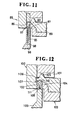
- Figure 11 is an enlarged fragmentary cross-sectional view of presser rolls according to still another embodiment of the present invention; and
- Figure 12 is an enlarged fragmentary cross-sectional view of presser rolls according to a still further embodiment of the present invention.
- The principles of the present invention are particularly advantageous when embodied in an apparatus for dimensioning slide fastener coupling elements, generally designated at 10 in Figure 1.
- As shown in Figure 2, the
dimensioning apparatus 10 is shown as coupled to anapparatus 11 for forming slide fastener coupling elements of synthetic resin. Thedimensioning apparatus 10 includes twounits 10A, 10B disposed at a discharge end of theapparatus 11 along a discharge path for the formed coupling elements. Thedimensioning apparatus 10 may have only one unit if the formed coupling elements have no tendency to spring back after they have been shaped to the required dimensions. - Since the two
units 10A, 10B are identical in construction, only one of theseunits 10A, 10B will be described hereinbelow. As shown in Figure 1, the apparatus 11 (Figure 2) for forming slide fastener coupling elements has a frame 12 (Figure 2) on which there are mountedsupport rods arm 15. To thearm 15, there is fixed a bracket orbase 16 on which a firsthorizontal shaft 17 is rotatably supported. Afirst presser roll 18 is rotatably mounted by a pair ofroller bearings 19 on thefirst shaft 17. - A second
vertical shaft 20 is rotatably mounted on aslide block 21 by a pair ofball bearings 23, the secondvertical shaft 20 being covered with asleeve 22. Theslide block 21 is mounted on thebracket 16 for sliding movement in the axial direction of the firsthorizontal shaft 17. As shown in Figure 3, the first horizontal and secondvertical shafts second presser roll 24 is fixed to an axial end of the secondvertical shaft 20 by means of abolt 25 with awasher 26 interposed between thebolt 25 and thesecond presser roll 24. Ascrew rod 27 rotatably mounted on theslide block 21 is threaded in an internally threadedhole 28 defined in thebracket 16, thescrew rod 27 having an axis parallel to the firsthorizontal shaft 19. By turning thescrew rod 27 to move the same axially, theslide block 21 and hence the secondvertical shaft 20 can be moved toward and away from the firsthorizontal shaft 17 in the directions of the arrows A, B. Thescrew rod 27 can be fixed in position with respect to thebracket 16 by alock nut 29. - As illustrated in Figure 3, the
first presser roll 18 comprises a first disk orwheel 30 and a second disk orwheel 31 that are concentrically fastened together by a pair ofbolts 32. Thefirst presser roll 18 has anannular recess 33 in an entire circumferential edge thereof facing the secondvertical shaft 20. Theannular recess 33 is defined by an annular step formed by a cross-sectionally L-shaped wall of thefirst disk 30 and thesecond disk 31, thesecond disk 31 being smaller in diameter than thefirst disk 30. Thefirst disk 30 has anannular end face 34 serving as a first presser surface lying perpendicularly to the firsthorizontal shaft 17. Thesecond disk 31 has a circumferential surface lying parallel to the firsthorizontal shaft 17 and shaped as aspur gear 35 composed of gear teeth each having a trapezoidal cross section. As shown in Figure 1, thefirst presser roll 18 also includes a third disk or wheel 31' attached by thebolts 32 to thefirst disk 30 remotely from thesecond disk 31. Thethird disk 35 is of an identical structure to that of thesecond disk 31. Therefore, thefirst presser roll 18 has twoannular recesses 33 on its axially opposite sides. - As shown in Figure 3, the
second presser roll 24 is composed of a fourth disk orwheel 36 and a fifth disk orwheel 37 connected concentrically to each other by a plurality ofbolts 38. Thesecond presser roll 24 has acircumferential surface 39 serving as a second presser surface lying in confronting relation to thefirst presser surface 34 of thefirst presser disk 18. Thesecond presser roll 24, or thefourth disk 36 thereof, has anend face 40 facing the firsthorizontal shaft 17 parallel thereto and an outer peripheral marginal edge constructed as apin gear 41 composed ofpin teeth 42 each having a frustoconical shape and projecting parallel to the secondvertical shaft 20. Thepin gear 41 is held in mesh with thespur gear 35. - As illustrated in Figure 1, a
third presser roll 43 is rotatably supported on thebracket 16 in horizontally spaced relation to thesecond presser roll 24, thethird presser roller 43 being identical in construction to thesecond presser roll 24. Thus, thethird presser roller 43 has a circumferential surface confronting theother recess 33 in thefirst presser roll 18 and a pin gear meshing with another spur gear 44 of thefirst presser roll 18, as shown in Figure 1. Thethird presser roller 43 is movable in the directions of the arrows C, D by means of ascrew rod 45. The first, second, andthird presser rollers - As shown in Figure 3, an annular array of
partition ridges 47 spaced at equal intervals projects from thefirst presser surface 34 into therecess 33, and another annular array ofpartition ridges 48 spaced at equal intervals projects from thesecond presser surface 39 toward thepartition ridges 47. Between the first andsecond disks bearing ring 49 having an outer circumferential surface serving as athird presser surface 50 extending along thepartition ridges 47 perpendicularly to the first and second presser surfaces 34, 49. - As shown in Figure 1, a
fourth presser roll 51 is rotatably supported by a thirdhorizontal shaft 52 and has a pair of axially spaced circumferential surfaces or fourth presser surfaces 53 each disposed adjacent to the first, second, and third presser surfaces 34, 39, 50. The thirdhorizontal shaft 52 extends substantially parallel to the firsthorizontal shaft 17 and is suported on aslide block 54 slidably supported on abracket 55 fixed to thesupport rod 14. Theslide block 54 is slidable in the axial direction of the secondvertical shaft 20 by ascrew rod 56 threaded in an internally threadedhole 57 defined in thebracket 55. Theslide block 54 and hence the thirdhorizontal shaft 52 are therefore movable in the directions of the arrow G, H by turning thescrew rod 56, which can thereafter be locked against rotation by alock nut 59. - The first, second, third, and fourth presser rolls 18, 24, 43, 51 are not positively driven, but are caused to rotate by two rows of slide fastener coupling elements 62 (Figure 2) which are successively formed by the
apparatus 11 and discharged by awithdrawal device 61 through theunits 10A, 10B. - Figures 4A through 4E show one form of slide fastener coupling elements which can be dimensioned by the dimensioning apparatus of the present invention. As shown in Figure 4A, a
coupling element assembly 63 comprises a plurality of parallelcontinuous coupling elements 64 of synthetic resin interconnected byconnectors 65 in a zigzag configuration, thecoupling elements 64 being also connected by a pair of connectingcords 66. Thecoupling element assembly 63 is bent into a cross-sectionally U-shape as indicated by the two-dot-and-dash lines in Figure 4B, and combined with acore cord 67 inserted betweenlegs coupling elements 64, as illustrated in Figures 4C and 4D. Thelegs coupling element 64 are interconnected by acoupling head 70. The formedcoupling element 64 has a thickness Wl between outer surfaces of thelegs coupling head 70 and ends of thelegs dimensioning apparatus 10 of the present invention. Thecoupling elements 64 dimensioned properly by thedimensioning apparatus 10 are woven into a longitudinal edge of a slidefastener stringer tape 71, as shown in Figure 4E. - Figures 5A through 5E illustrate another form of slide fastener coupling elements. As shown in Figure 5A, a
coupling element assembly 72 is composed ofcontinuous coupling elements 74 of synthetic resin having a meandering or zigzag pattern, thecoupling elements 74 being interconnected byconnectors 75. Thecoupling element assembly 72 is bent about a longitudinal central axis into a U-shaped cross section as indicated by the two-dot-and-dash lines in Figure SB. Each of thebent coupling elements 74 has a pair ofleas 76, 77 interconnected by acoupling head 78 as sham in Figures 5C and 5D. Thecoupling element 74 has illustrated dimensions, that is, thicknesses W2, W3 and a length L2, controlled by the dimensioning apparatus of the invention. The dimensionedcoupling elements 74 are sewn bysewing threads 79 to a slidefastener stringer tape 80 along a longitudinal edge thereof. - Figures 6A and 6B show an
assembly 82 of discrete slidefastener coupling elements 83 of metal mounted by staking on a reinforcingcord 84 on a longitudinal edge of a slidefastener stringer tape 85. The dimensioning apparatus of the invention controlls a thickness W4 of thecoupling elements 83. - The first and second presser rolls 18, 24 serve to press the legs of the coupling elements with the first and second presser surfaces 34, 39 to achieve the prescribed widths Wl, W2, W3, W4. The first and second presser surfaces 34, 39 therefore have closest confronting portions spaced apart from each other by a distance W equal to one of the widths Wl, W2, W3, W4,' as illustrated in Figure 7.
- The third and fourth presser surfaces 50, 53 have closest confronting portions spaced apart from each other by a distance L which is equalized to one of the lengths Ll, L2 of the coupling elements.
- Operation of the
dimensioning apparatus 10 is as follows. - First, dimensioning of the
coupling elements 64 shown in Figures 4C and 4D will be described. Thedimensioning apparatus 10 can process two rows ofsuch coupling elements 64 to dimension the same simultaneously. Since the two rows of the coupling elements are dimensioned in the same manner, however, the processing of only one row of the coupling elements will be described in detail. Thescrew rods 27, 56 are turned about their own axes to slide the slide blocks 21, 54 and hence the second andthird shafts 20, 52 in the directions of the arrows B, H, respectively. The second and fourth presser rolls 24, 51 are moved from the positions of Figures 1 and 7 away from thefirst presser roll 18 into the positions indicated by the two-dot-and-dash lines in Figure 1 or the positions of Figure 8, in which the first, second, third, and fourth presser surfaces 34, 39, 50, 53 are spaced from each other at increased distances. The row of thecoupling elements 64 is then inserted between the first, second, thrrd, and fourth presser surfaces 34, 39, 50, 53. - Thereafter, the
screw rods first presser roll 18, until the first through fourth presser surfaces 24, 29, 50, 53 are spaced at the distances L, W from the confronting presser surfaces, as illustrated in Figure 7. - As the
coupling elements 64 are fed along in the direction of the arrow I by the withdrawal device 61 (Figure 2), the first, second, and fourth presser rolls 18, 24, 51 are rotated by thecoupling elements 64. At this time, the first and second presser rolls 18, 24 are synchronously rotated by meshing engagement between thespur gear 35 and thepin gear 41. - The
coupling elements 64, as they move through the first, second, and fourth presser rolls 18, 24, 51, are pressed by the first through fourth presser surfaces 34, 39, 50, 53 to the prescribed dimensions Wl, Ll. At this time, thepartition ridges legs legs third presser surface 50 while the ends of thelegs fourth surface 53. Accordingly, thelegs coupling elements 64 are not subjected to undesired scratches or damages which would otherwise result from asynchronous rotation of the first and second presser surfaces 34, 39. The meshing engagement between thespur gear 35 and thepin gear 41 permits them to remain uniformly intermeshed without wobbling or forced meshing engagement even when thesecond presser roll 24 is axially displaced in the directions of the arrows A, B (Figure 1). Accordingly, the first and second presser rolls 18, 24 are allowed to rotate smoothly and uniformly. When the first, second, and fourth presser rolls 18, 24, 51 are relatively displaced for adjusting their spacings while thecoupling elements 64 are being dimensioned, the first and second presser rolls 18, 24 rotate smoothly and uniformly in complete synchronism as thepin gear 41 remainsin mesh with thespur gear 35. - Figure 10 shows a dimensioning apparatus according to another embodiment for dimensioning the
coupling elements 74 as shown in Figures 5A through 5D. The dimensioning apparatus of Figure 10 includes afirst presser roll 90 having afirst presser surface 91 and asecond presser roll 92 having asecond presser surface 93 facing thefirst presser surface 91. The first and second presser surfaces 91, 93 have raisedportions portions - According to still another embodiment shown in Figure 11, a dimensioning apparatus is designed for dimensioning the
coupling elements 83 illustrated in Figures 6A and 6B. The dimensioning apparatus includes athird presser roll 96 having afourth presser surface 97 and aslot 98 opening radially outwardly for receiving theslide fastener tape 95 therein. For dimensioning thecoupling elements 83 of metal, first and second presser surfaces 86, 87 of first and second presser rolls 88, 89 require no partition ridges. - Figure 12 shows a dimensioning apparatus according to a still further embodiment of the present invention. The dimensioning apparatus comprises a
first presser roll 100 having aspur gear 101 and afirst presser surface 102, asecond presser roll 103 having asecond presser surface 104 confronting thefirst presser surface 102. Thesecond presser roll 103 also has apin gear 105 and a radially outwardly projectingflange 106 having athird presser surface 107 facing away from thepin gear 105 toward afourth presser surface 108 of athird presser roll 109. In operation, the coupling heads 110 ofcoupling elements 111 are pressed against thethird presser surface 107 by thefourth presser surface 108 of thethird presser roll 109 which engages the legs of thecoupling elements 111.
Claims (7)
Applications Claiming Priority (2)
| Application Number | Priority Date | Filing Date | Title |
|---|---|---|---|
| JP99556/84 | 1984-05-17 | ||
| JP59099556A JPS60242804A (en) | 1984-05-17 | 1984-05-17 | Dimension limiting apparatus of slide fastener element |
Publications (3)
| Publication Number | Publication Date |
|---|---|
| EP0162218A2 true EP0162218A2 (en) | 1985-11-27 |
| EP0162218A3 EP0162218A3 (en) | 1988-03-30 |
| EP0162218B1 EP0162218B1 (en) | 1989-12-27 |
Family
ID=14250429
Family Applications (1)
| Application Number | Title | Priority Date | Filing Date |
|---|---|---|---|
| EP85103019A Expired EP0162218B1 (en) | 1984-05-17 | 1985-03-15 | Apparatus for dimensioning slide fastener coupling elements |
Country Status (13)
| Country | Link |
|---|---|
| US (1) | US4599065A (en) |
| EP (1) | EP0162218B1 (en) |
| JP (1) | JPS60242804A (en) |
| KR (1) | KR860001833B1 (en) |
| AU (1) | AU552520B2 (en) |
| BR (1) | BR8502473A (en) |
| CA (1) | CA1229471A (en) |
| DE (1) | DE3574950D1 (en) |
| ES (1) | ES8607111A1 (en) |
| GB (1) | GB2158873B (en) |
| HK (1) | HK90589A (en) |
| MY (1) | MY101816A (en) |
| SG (1) | SG56689G (en) |
Cited By (1)
| Publication number | Priority date | Publication date | Assignee | Title |
|---|---|---|---|---|
| US7265178B2 (en) | 2003-07-11 | 2007-09-04 | Construction Research & Technology Gmbh | Polyurethane-polymer hybrid-dispersion with enhanced surface properties, method for the production and utilization thereof |
Families Citing this family (9)
| Publication number | Priority date | Publication date | Assignee | Title |
|---|---|---|---|---|
| JPS60142805A (en) * | 1983-12-29 | 1985-07-29 | ワイケイケイ株式会社 | Method and apparatus for producing fastener element for slide fastener |
| JPH04324162A (en) * | 1991-04-24 | 1992-11-13 | Kenwood Corp | Optical disk reproducing device |
| JP3275932B2 (en) * | 1994-08-02 | 2002-04-22 | ワイケイケイ株式会社 | Method and apparatus for forming continuous element row for slide fastener |
| US5688539A (en) * | 1996-05-03 | 1997-11-18 | Chung Shan Institute Of Science & Technology | Zipper teeth forming mechanism for zipper forming machines |
| JP3320636B2 (en) * | 1997-06-12 | 2002-09-03 | ワイケイケイ株式会社 | Drawer insertion unit of slider for zipper with pull in insert molding machine |
| US6783350B2 (en) * | 2002-07-03 | 2004-08-31 | Hung An Chen | Apparatus for manufacturing slide fastener coil-shaped continuous element row |
| US6783351B2 (en) * | 2002-07-03 | 2004-08-31 | Hung An Chen | Apparatus for manufacturing slide fastener spiral continuous element row |
| TWI220645B (en) * | 2002-10-07 | 2004-09-01 | Gi Kao Young Industry Co Ltd | Nylon zipper teeth and forming screw for producing this nylon zipper teeth |
| CN106089884B (en) * | 2016-07-29 | 2017-12-22 | 蚌埠富轩商贸有限公司 | A kind of rotary-type photo frame pressurizing unit |
Citations (1)
| Publication number | Priority date | Publication date | Assignee | Title |
|---|---|---|---|---|
| US4406849A (en) * | 1980-08-19 | 1983-09-27 | Yoshida Kogyo K. K. | Method of and apparatus for continuously manufacturing slide fastener coupling elements |
Family Cites Families (1)
| Publication number | Priority date | Publication date | Assignee | Title |
|---|---|---|---|---|
| JPS5651326A (en) * | 1979-10-01 | 1981-05-08 | Yoshida Kogyo Kk <Ykk> | Method and apparatus for manufacturing slide fastener with synthetic resin zipper |
-
1984
- 1984-05-17 JP JP59099556A patent/JPS60242804A/en active Granted
-
1985
- 1985-03-01 GB GB08505308A patent/GB2158873B/en not_active Expired
- 1985-03-05 CA CA000475730A patent/CA1229471A/en not_active Expired
- 1985-03-06 AU AU39552/85A patent/AU552520B2/en not_active Ceased
- 1985-03-15 DE DE8585103019T patent/DE3574950D1/en not_active Expired - Lifetime
- 1985-03-15 EP EP85103019A patent/EP0162218B1/en not_active Expired
- 1985-04-29 KR KR1019850002887A patent/KR860001833B1/en not_active IP Right Cessation
- 1985-05-14 US US06/733,885 patent/US4599065A/en not_active Expired - Fee Related
- 1985-05-16 BR BR8502473A patent/BR8502473A/en not_active IP Right Cessation
- 1985-05-17 ES ES543234A patent/ES8607111A1/en not_active Expired
-
1987
- 1987-08-17 MY MYPI87001350A patent/MY101816A/en unknown
-
1989
- 1989-08-25 SG SG566/89A patent/SG56689G/en unknown
- 1989-11-16 HK HK905/89A patent/HK90589A/en unknown
Patent Citations (1)
| Publication number | Priority date | Publication date | Assignee | Title |
|---|---|---|---|---|
| US4406849A (en) * | 1980-08-19 | 1983-09-27 | Yoshida Kogyo K. K. | Method of and apparatus for continuously manufacturing slide fastener coupling elements |
Cited By (1)
| Publication number | Priority date | Publication date | Assignee | Title |
|---|---|---|---|---|
| US7265178B2 (en) | 2003-07-11 | 2007-09-04 | Construction Research & Technology Gmbh | Polyurethane-polymer hybrid-dispersion with enhanced surface properties, method for the production and utilization thereof |
Also Published As
| Publication number | Publication date |
|---|---|
| GB2158873B (en) | 1988-02-03 |
| EP0162218B1 (en) | 1989-12-27 |
| MY101816A (en) | 1992-01-31 |
| CA1229471A (en) | 1987-11-24 |
| AU552520B2 (en) | 1986-06-05 |
| JPH0128562B2 (en) | 1989-06-05 |
| JPS60242804A (en) | 1985-12-02 |
| BR8502473A (en) | 1986-01-28 |
| SG56689G (en) | 1989-12-29 |
| KR850008612A (en) | 1985-12-21 |
| AU3955285A (en) | 1985-11-21 |
| GB8505308D0 (en) | 1985-04-03 |
| ES8607111A1 (en) | 1986-06-01 |
| KR860001833B1 (en) | 1986-10-24 |
| US4599065A (en) | 1986-07-08 |
| HK90589A (en) | 1989-11-24 |
| GB2158873A (en) | 1985-11-20 |
| EP0162218A3 (en) | 1988-03-30 |
| ES543234A0 (en) | 1986-06-01 |
| DE3574950D1 (en) | 1990-02-01 |
Similar Documents
| Publication | Publication Date | Title |
|---|---|---|
| EP0162218B1 (en) | Apparatus for dimensioning slide fastener coupling elements | |
| DE2930446C2 (en) | Tape cartridge | |
| DE2520544A1 (en) | PROCESS FOR MANUFACTURING PIPES WITH DIAMETER CONTROL AND MACHINE FOR CARRYING OUT THE PROCESS | |
| DE60004431T2 (en) | Method and device for forming a tire reinforcement layer | |
| DE69931678T2 (en) | Assembly head for a device for mounting electronic components | |
| EP0091690B1 (en) | Apparatus for shaping coiled slide fastener coupling elements | |
| EP0581092B1 (en) | Vacuum-forming process for the production of a plastic plate provided with studs | |
| DE3326858C1 (en) | Device for producing a wound helix | |
| WO1999032804A1 (en) | Production of a toothed hollow cylindrical part | |
| DE4335505C1 (en) | Device for producing a gear part which is toothed on the outside | |
| DE2519278A1 (en) | METHOD OF FORMING GLASS PANELS BY ROLLING | |
| DE3204668A1 (en) | Method and apparatus for the production of belt pulleys | |
| DE4322114C2 (en) | Deflection roller | |
| EP0911091B1 (en) | Wire rolling apparatus | |
| DE2741502B2 (en) | Device for bending the connecting wires of an electronic component and fixing the same on a carrier tape | |
| DE3327288C2 (en) | ||
| AT397220B (en) | METHOD AND DEVICE FOR AUTOMATICALLY MOUNTING AND FASTENING A CLAMP | |
| DE3138560A1 (en) | "METHOD AND DEVICE FOR FOLDING AND SHAPING A CONTINUOUS CHAIN OF ZIPPER COUPLING ELEMENT BODIES" | |
| DD247617A5 (en) | METHOD AND DEVICE FOR PRODUCING COMPONENTS FROM LEAD | |
| EP1473096A1 (en) | Roll forming device for roll forming sheet metal strips and roller segment for such a roll forming device | |
| DE2420329B2 (en) | Method and apparatus for building a belt for a pneumatic tire | |
| GB2208489A (en) | Apparatus for manufacturing continuous zigzag coupling elements for slide fasteners | |
| CN107981489B (en) | Thickness adjusting device and thickness adjusting method for slide fastener chain | |
| DE3405291A1 (en) | Machine tool | |
| DE2657241A1 (en) | TUBULAR STACKING DEVICE FOR COINS |
Legal Events
| Date | Code | Title | Description |
|---|---|---|---|
| PUAI | Public reference made under article 153(3) epc to a published international application that has entered the european phase |
Free format text: ORIGINAL CODE: 0009012 |
|
| AK | Designated contracting states |
Designated state(s): BE DE FR IT NL |
|
| PUAL | Search report despatched |
Free format text: ORIGINAL CODE: 0009013 |
|
| AK | Designated contracting states |
Kind code of ref document: A3 Designated state(s): BE DE FR IT NL |
|
| 17P | Request for examination filed |
Effective date: 19880627 |
|
| 17Q | First examination report despatched |
Effective date: 19890307 |
|
| GRAA | (expected) grant |
Free format text: ORIGINAL CODE: 0009210 |
|
| AK | Designated contracting states |
Kind code of ref document: B1 Designated state(s): BE DE FR IT NL |
|
| ITF | It: translation for a ep patent filed |
Owner name: JACOBACCI & PERANI S.P.A. |
|
| ET | Fr: translation filed | ||
| REF | Corresponds to: |
Ref document number: 3574950 Country of ref document: DE Date of ref document: 19900201 |
|
| PLBE | No opposition filed within time limit |
Free format text: ORIGINAL CODE: 0009261 |
|
| STAA | Information on the status of an ep patent application or granted ep patent |
Free format text: STATUS: NO OPPOSITION FILED WITHIN TIME LIMIT |
|
| 26N | No opposition filed | ||
| ITTA | It: last paid annual fee | ||
| PGFP | Annual fee paid to national office [announced via postgrant information from national office to epo] |
Ref country code: BE Payment date: 19931223 Year of fee payment: 10 |
|
| PGFP | Annual fee paid to national office [announced via postgrant information from national office to epo] |
Ref country code: FR Payment date: 19940121 Year of fee payment: 10 |
|
| PGFP | Annual fee paid to national office [announced via postgrant information from national office to epo] |
Ref country code: NL Payment date: 19940331 Year of fee payment: 10 Ref country code: DE Payment date: 19940331 Year of fee payment: 10 |
|
| ITPR | It: changes in ownership of a european patent |
Owner name: CAMBIO RAGIONE SOCIALE;YKK CORPORATION |
|
| REG | Reference to a national code |
Ref country code: FR Ref legal event code: CD |
|
| PG25 | Lapsed in a contracting state [announced via postgrant information from national office to epo] |
Ref country code: BE Effective date: 19950331 |
|
| BERE | Be: lapsed |
Owner name: YOSHIDA KOGYO K.K. Effective date: 19950331 |
|
| PG25 | Lapsed in a contracting state [announced via postgrant information from national office to epo] |
Ref country code: NL Effective date: 19951001 |
|
| PG25 | Lapsed in a contracting state [announced via postgrant information from national office to epo] |
Ref country code: FR Free format text: LAPSE BECAUSE OF NON-PAYMENT OF DUE FEES Effective date: 19951130 |
|
| NLV4 | Nl: lapsed or anulled due to non-payment of the annual fee |
Effective date: 19951001 |
|
| PG25 | Lapsed in a contracting state [announced via postgrant information from national office to epo] |
Ref country code: DE Effective date: 19951201 |
|
| REG | Reference to a national code |
Ref country code: FR Ref legal event code: ST |