EP0246856A2 - Stone tiles - Google Patents
Stone tiles Download PDFInfo
- Publication number
- EP0246856A2 EP0246856A2 EP87304415A EP87304415A EP0246856A2 EP 0246856 A2 EP0246856 A2 EP 0246856A2 EP 87304415 A EP87304415 A EP 87304415A EP 87304415 A EP87304415 A EP 87304415A EP 0246856 A2 EP0246856 A2 EP 0246856A2
- Authority
- EP
- European Patent Office
- Prior art keywords
- layer
- tile
- stone
- sub
- edge
- Prior art date
- Legal status (The legal status is an assumption and is not a legal conclusion. Google has not performed a legal analysis and makes no representation as to the accuracy of the status listed.)
- Withdrawn
Links
- 239000004575 stone Substances 0.000 title claims abstract description 43
- 239000000758 substrate Substances 0.000 claims abstract description 33
- 210000002105 tongue Anatomy 0.000 claims abstract description 21
- 238000005253 cladding Methods 0.000 claims abstract description 14
- 238000009408 flooring Methods 0.000 claims abstract description 10
- 239000000463 material Substances 0.000 claims description 28
- 239000000853 adhesive Substances 0.000 claims description 6
- 230000001070 adhesive effect Effects 0.000 claims description 6
- 239000004033 plastic Substances 0.000 claims description 5
- 229920003023 plastic Polymers 0.000 claims description 5
- 239000003292 glue Substances 0.000 claims description 4
- 239000003822 epoxy resin Substances 0.000 claims description 3
- 229920000647 polyepoxide Polymers 0.000 claims description 3
- 229920001651 Cyanoacrylate Polymers 0.000 claims description 2
- MWCLLHOVUTZFKS-UHFFFAOYSA-N Methyl cyanoacrylate Chemical compound COC(=O)C(=C)C#N MWCLLHOVUTZFKS-UHFFFAOYSA-N 0.000 claims description 2
- 230000000295 complement effect Effects 0.000 claims description 2
- 239000007769 metal material Substances 0.000 claims 1
- 239000004579 marble Substances 0.000 description 41
- 238000006073 displacement reaction Methods 0.000 description 4
- 229920005989 resin Polymers 0.000 description 2
- 239000011347 resin Substances 0.000 description 2
- 239000003795 chemical substances by application Substances 0.000 description 1
- 238000010276 construction Methods 0.000 description 1
- 239000003365 glass fiber Substances 0.000 description 1
- 239000010438 granite Substances 0.000 description 1
- 238000009434 installation Methods 0.000 description 1
- 238000004519 manufacturing process Methods 0.000 description 1
- 239000004570 mortar (masonry) Substances 0.000 description 1
- 239000013585 weight reducing agent Substances 0.000 description 1
Images

Classifications
-
- E—FIXED CONSTRUCTIONS
- E04—BUILDING
- E04F—FINISHING WORK ON BUILDINGS, e.g. STAIRS, FLOORS
- E04F15/00—Flooring
- E04F15/02—Flooring or floor layers composed of a number of similar elements
-
- E—FIXED CONSTRUCTIONS
- E04—BUILDING
- E04F—FINISHING WORK ON BUILDINGS, e.g. STAIRS, FLOORS
- E04F2203/00—Specially structured or shaped covering, lining or flooring elements not otherwise provided for
- E04F2203/06—Specially structured or shaped covering, lining or flooring elements not otherwise provided for comprising two layers fixedly secured to one another, in offset relationship in order to form a rebate
-
- Y—GENERAL TAGGING OF NEW TECHNOLOGICAL DEVELOPMENTS; GENERAL TAGGING OF CROSS-SECTIONAL TECHNOLOGIES SPANNING OVER SEVERAL SECTIONS OF THE IPC; TECHNICAL SUBJECTS COVERED BY FORMER USPC CROSS-REFERENCE ART COLLECTIONS [XRACs] AND DIGESTS
- Y10—TECHNICAL SUBJECTS COVERED BY FORMER USPC
- Y10T—TECHNICAL SUBJECTS COVERED BY FORMER US CLASSIFICATION
- Y10T428/00—Stock material or miscellaneous articles
- Y10T428/16—Two dimensionally sectional layer
- Y10T428/163—Next to unitary web or sheet of equal or greater extent
-
- Y—GENERAL TAGGING OF NEW TECHNOLOGICAL DEVELOPMENTS; GENERAL TAGGING OF CROSS-SECTIONAL TECHNOLOGIES SPANNING OVER SEVERAL SECTIONS OF THE IPC; TECHNICAL SUBJECTS COVERED BY FORMER USPC CROSS-REFERENCE ART COLLECTIONS [XRACs] AND DIGESTS
- Y10—TECHNICAL SUBJECTS COVERED BY FORMER USPC
- Y10T—TECHNICAL SUBJECTS COVERED BY FORMER US CLASSIFICATION
- Y10T428/00—Stock material or miscellaneous articles
- Y10T428/19—Sheets or webs edge spliced or joined
- Y10T428/192—Sheets or webs coplanar
- Y10T428/195—Beveled, stepped, or skived in thickness
-
- Y—GENERAL TAGGING OF NEW TECHNOLOGICAL DEVELOPMENTS; GENERAL TAGGING OF CROSS-SECTIONAL TECHNOLOGIES SPANNING OVER SEVERAL SECTIONS OF THE IPC; TECHNICAL SUBJECTS COVERED BY FORMER USPC CROSS-REFERENCE ART COLLECTIONS [XRACs] AND DIGESTS
- Y10—TECHNICAL SUBJECTS COVERED BY FORMER USPC
- Y10T—TECHNICAL SUBJECTS COVERED BY FORMER US CLASSIFICATION
- Y10T428/00—Stock material or miscellaneous articles
- Y10T428/24—Structurally defined web or sheet [e.g., overall dimension, etc.]
- Y10T428/24777—Edge feature
Definitions
- This invention relates to a tile for use as flooring, wall cladding or the like, and which when used with other similar tiles presents a stone surface.
- stone as used herein is meant to refer to any of the naturally-occurring materials often employed for purposes such as flooring, wall claddings or the like and should be construed to include natural materials such as granite, marble and the like.
- marble slabs for flooring are normally supplied with a much greater thickness than really is necessary, from the point of view of providing a satisfactory floor, when laid on a suitable base. For example, it is common to supply marble slabs for flooring with a thickness of at least 25 mm.
- Marble is however relatively dense and so the handling of such thick slabs of marble is not easy, increasing the likelihood of damage and breakage on account of the overall weight of each slab. Moreover, thick slabs give rise to high transportation costs for a given floor area to be covered, on account of the weight per unit area of marble slabs suitable for use as flooring.
- marble slabs When a wall is to be clad with marble, similar considerations apply, except that the marble slabs have to be affixed to the vertical wall surface by appropriate means able to withstand the particular installation conditions. For example, it may be necessary separately to drill and peg each marble slab so as to minimise the risk of a slab falling away from the vertical wall surface.
- this invention provides a tile for use in flooring, wall cladding or the like, which tile comprises in combination a layer of a natural stone material (as defined hereinbefore) and a substrate layer of essentially the same shape as the stone layer, the substrate layer being adhered to a face of the stone layer and being relatively non-brittle as compared to the stone material, and the thickness of the stone layer being relatively small as compared to conventional floor or wall claddings of a similar stone material.
- the required stone material is cut so as to have a relatively small thickness, as compared to conventional floor or wall claddings of the same stone material.
- a cut stone would, by itself, have insufficient strength to permit normal handling, fixing and use.
- the cut stone material is adhered to a substrate, which is relatively non-brittle. In this way, considerable strength can be imparted to the tile, so minimising the likelihood of the stone material breaking during transit or fixing, and at the same time the weight per unit area may be greatly reduced, as compared to conventional stone slabs for floor covering or wall cladding.
- the thickness of the marble slabs would be at least 25 mm for a slab measuring about 300 mm ⁇ 300 mm.
- the thickness of the marble layer may be as small as 10 mm, or even less, for a similar tile size, giving a weight reduction of about 60% as compared to the conventional marble slab, but making no allowance for the weight of the substrate. The latter typically would be very small, as compared to the weight of the marble.
- the substrate layer may be made of any suitable material displaying sufficient strength to give adequate support to the stone layer.
- the substrate layer may comprise a metallic sheet, though it is preferred for a relatively firm or rigid plastics material to be employed for this purpose.
- the adhesive used to bond the two layers together should be selected having due regard to the nature of both the substrate layer and the stone layer, but mention may here be made of the cyanoacrylate family of glues and epoxy resin glues. The selection of a suitable grade of adhesive will not present any particular difficulty, provided sufficient consideration is given to the materials to be bonded.
- a projecting tongue may be provided along one edge of the substrate layer, to project in a plane generally parallel to the bonded surfaces of the stone and substrate layers. Then, by providing a complementary groove along that edge of the substrate layer opposed to that having the projecting tongue, the substrate layer of one tile may be interlocked with the substrate layer of another like tile during the fixing of the tiles. This reduces the likelihood of any one tile coming free, and moreover assists the fixing, to ensure an even and regular finish.
- projecting tongues are provided on two adjacent edges of the substrate layer, the respective two opposed edges having correspondingly-formed grooves, so as to allow the interlocking of tiles on all four edges.
- the material of the substrate layer furthest from the stone layer may then be employed to permit the fastening of the tile to the surface, for example by means of screws extending through holes provided in that projecting tab and fitted into plugged holes provided in the wall or floor.
- the material of the substrate layer must be cut back along the opposed edge, in order that two tiles may properly be fitted together.
- the substrate layer comprises at least two but advantageously three sub-layers bonded together, each sub-layer being of essentially the same overall shape but the sub-layers being displaced out of exact alignment one with another so as thereby to define, along two edges (of a rectangular tile), projecting tongues and to define, along the other two edges, grooves to receive the tongues of corresponding tiles.
- the displacement may be such as also to provide a projecting tab suitable for fixing the tiles to a surface, as has been described above.
- the tongues and grooves would be defined by a displaced central sub-layer, and the grooves between the other two sub-layers.
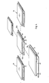
- a marble tile 10 intended for use either for flooring or for the cladding of walls.
- the tile 10 has a natural marble layer 11 and bonded thereto with a suitable adhesive is a substrate 12 made up from three similar sub-layers 13, these sub-layers also being bonded one to another.
- Each sub-layer 13 is cut from a sheet of semi-rigid plastics material so as to have substantially the same overall shape and size, which corresponds also to the shape and size of the marble layer 11.
- the sub-layer 13A bonded directly to the marble layer 11, is disposed so that its four edges are in alignment with the four edges of the marble layer itself.
- the two lower sub-layers 13B and 13C though having the same overall shape and size as the marble 11, are displaced so that their respective edges are out of line with the corresponding edges of sub-layer 13A and the marble layer 11, as shown in the drawings.
- the central sub-layer 13B projects beyond edges 14 and 15 of the marble layer 11, so as to define two projecting tongues 16 and 17.
- the displacement of sub-layer 13B in this way also then serves to define two grooves 18 and 19, below the edges 20 and 21 of the marble layer 10, which edges are respectively opposed to edges 15 and 14. It will be appreciated that the depth of each groove inwardly of the tile 10 from the marble layer edge is precisely equal to the amount of projection of the tongue beyond the opposite edge of the marble layer, so permitting the tongue of a first tile fully to be received in the corresponding groove of a second tile, laid alongside the first tile, with the marble layers of the two tiles closely adjacent.
- Sub-layer 13C also is displaced out of register with sub-layer 13A, but only with respect to edges 14 and 21 of the marble layer 11.
- a tab 22 is provided which projects beyond edge 21 of the tile.
- This projecting tab 22 is provided with two fixing holes 23, to which access may be gained as the tiles are being affixed to a floor or a wall. Equally, a corresponding recess 24 is formed below edge 14 of the marble layer, to receive the projecting tab of another tile.
- FIGS 2, 3 and 4 collectively show how tiles of this invention interlock together. It will be appreciated that as tiling of a surface is continued, using tiles of this invention, each edge of any given tile is interlocked with the adjacent edge of another tile by virtue of the interfitting tongues and grooves, effectively defined by displacement of the respective central sub-layers 13B of the tiles. Moreover, each tile may be affixed to the surface being tiled by means of screws (not shown) passing through the holes 23 formed in the projecting tabs 22, so giving completely invisible fixings for the tiles.
- a typical tile of this invention may have a plan area measuring 300 mm ⁇ 300 mm and the thickness of the marble layer 11 may be about 10 mm.
- the upper face of the marble layer may be polished in the usual way, though the lower face preferably is left unpolished so as to facilitate the bonding of the marble layer to the substrate 12, for example with an epoxy resin adhesive.
- Each sub-layer of the substrate 12 may be formed of a synthetic plastics or resin material, suitably reinforced for example with glass fibres, if required, so as to give sufficient rigidity thereto.
- the sub-layers should be bonded together with an appropriate grade of adhesive, having regard to the nature of the plastics or resin material employed for those sub-layers.
- sub-layer 13A is of the same shape and size as the marble layer 11, and the edges of the sub-layer 13A and the marble layer 11 are wholly in register, that sub-layer may be omitted.
- the displacement of the sub-layer 13B will define th ⁇ grooves for receiving the projecting tongues directly between the marble layer 11 and the sub-layer 13C, and since the edge region of the marble layer 11 will be unsupported by a sub-layer along two edges, special care during handling will be required to prevent damage to those two edges.
- tiling may proceed most rapidly with each tile being affixed simply by means of screws passing through holes 23, so giving a most pleasing and aesthetic result with wholly invisible fixings for the tiles.
- FIG 5 a further embodiment of tile of this invention is illustrated, wherein only two sub-layers 13B and 13C are provided, sub-layer 13A being omitted.
- sub-layer 13A in the embodiment of Figures 1 to 4 is of the same shape and size as the tile 11, and is wholly in register therewith, the tile of Figure 5 clearly may be used in just the same manner as the tile of Figures 1 to 4; the tile is however slightly thinner.
Abstract
Description
- This invention relates to a tile for use as flooring, wall cladding or the like, and which when used with other similar tiles presents a stone surface. The term "stone" as used herein is meant to refer to any of the naturally-occurring materials often employed for purposes such as flooring, wall claddings or the like and should be construed to include natural materials such as granite, marble and the like.
- When a marble floor is required in a building, it is the usual practice to provide a level base on which pre-prepared slabs of marble are laid, with a suitable bedding agent (such as mortar) between the base and the slabs. Because marble is a relatively brittle stone material, breakages in transit and when laying the floor are quite common. In an attempt to reduce the likelihood of breakage, and so also to give the marble slabs a sufficient strength for the intended purpose, marble slabs for flooring are normally supplied with a much greater thickness than really is necessary, from the point of view of providing a satisfactory floor, when laid on a suitable base. For example, it is common to supply marble slabs for flooring with a thickness of at least 25 mm. Marble is however relatively dense and so the handling of such thick slabs of marble is not easy, increasing the likelihood of damage and breakage on account of the overall weight of each slab. Moreover, thick slabs give rise to high transportation costs for a given floor area to be covered, on account of the weight per unit area of marble slabs suitable for use as flooring.
- When a wall is to be clad with marble, similar considerations apply, except that the marble slabs have to be affixed to the vertical wall surface by appropriate means able to withstand the particular installation conditions. For example, it may be necessary separately to drill and peg each marble slab so as to minimise the risk of a slab falling away from the vertical wall surface.
- The foregoing problems also apply to the use of other natural stone materials in the construction of buildings, when employed as floor or wall coverings: the stone materials must be cut to have a thickness sufficiently great to give the cut slabs adequate strength to withstand the handling and transport thereof, even though the service conditions may require only relatively thin slabs. Despite this, experience shows that breakages of cut slabs frequently occur. Also, on account of the thickness of each slab, the overall weight of the stone material required to cover a given area is relatively high, leading to high costs both for the purchase of the stone slabs and for transport thereof.
- It is consequently a principal aim of the present invention to provide a stone tile suitable for use as a wall cladding or a floor covering, which tile when in use presents a stone face and which substantially reduces the disadvantages mentioned above, both regarding the likelihood of breakage and the not inconsiderable weight of the known stone slab materials.
- Accordingly, this invention provides a tile for use in flooring, wall cladding or the like, which tile comprises in combination a layer of a natural stone material (as defined hereinbefore) and a substrate layer of essentially the same shape as the stone layer, the substrate layer being adhered to a face of the stone layer and being relatively non-brittle as compared to the stone material, and the thickness of the stone layer being relatively small as compared to conventional floor or wall claddings of a similar stone material.
- It will be appreciated in order to manufacture a tile according to the present invention, the required stone material is cut so as to have a relatively small thickness, as compared to conventional floor or wall claddings of the same stone material. Such a cut stone would, by itself, have insufficient strength to permit normal handling, fixing and use. However, in this invention the cut stone material is adhered to a substrate, which is relatively non-brittle. In this way, considerable strength can be imparted to the tile, so minimising the likelihood of the stone material breaking during transit or fixing, and at the same time the weight per unit area may be greatly reduced, as compared to conventional stone slabs for floor covering or wall cladding. For example, in the case of a conventional marble floor or wall cladding, the thickness of the marble slabs would be at least 25 mm for a slab measuring about 300 mm × 300 mm. By contrast, when making a marble tile according to the present invention, the thickness of the marble layer may be as small as 10 mm, or even less, for a similar tile size, giving a weight reduction of about 60% as compared to the conventional marble slab, but making no allowance for the weight of the substrate. The latter typically would be very small, as compared to the weight of the marble.
- The substrate layer may be made of any suitable material displaying sufficient strength to give adequate support to the stone layer. For example, the substrate layer may comprise a metallic sheet, though it is preferred for a relatively firm or rigid plastics material to be employed for this purpose. The adhesive used to bond the two layers together should be selected having due regard to the nature of both the substrate layer and the stone layer, but mention may here be made of the cyanoacrylate family of glues and epoxy resin glues. The selection of a suitable grade of adhesive will not present any particular difficulty, provided sufficient consideration is given to the materials to be bonded.
- By providing a relatively thick substrate layer, a projecting tongue may be provided along one edge of the substrate layer, to project in a plane generally parallel to the bonded surfaces of the stone and substrate layers. Then, by providing a complementary groove along that edge of the substrate layer opposed to that having the projecting tongue, the substrate layer of one tile may be interlocked with the substrate layer of another like tile during the fixing of the tiles. This reduces the likelihood of any one tile coming free, and moreover assists the fixing, to ensure an even and regular finish. Most preferably, for the case of a rectangular tile, projecting tongues are provided on two adjacent edges of the substrate layer, the respective two opposed edges having correspondingly-formed grooves, so as to allow the interlocking of tiles on all four edges.
- For the preferred arrangement of tile, where the substrate layer has a tongue and a groove provided along at least a pair of opposed edges, it is preferred for the material of the substrate layer furthest from the stone layer to project laterally beyond the edge of the stone layer, along the grooved edge. Such a projecting tab, which will lie against the surface to which the tile is to be affixed, may then be employed to permit the fastening of the tile to the surface, for example by means of screws extending through holes provided in that projecting tab and fitted into plugged holes provided in the wall or floor. For such an arrangement, the material of the substrate layer must be cut back along the opposed edge, in order that two tiles may properly be fitted together.
- Most conveniently, the substrate layer comprises at least two but advantageously three sub-layers bonded together, each sub-layer being of essentially the same overall shape but the sub-layers being displaced out of exact alignment one with another so as thereby to define, along two edges (of a rectangular tile), projecting tongues and to define, along the other two edges, grooves to receive the tongues of corresponding tiles. The displacement may be such as also to provide a projecting tab suitable for fixing the tiles to a surface, as has been described above. For the preferred arrangement of three sub-layers, the tongues and grooves would be defined by a displaced central sub-layer, and the grooves between the other two sub-layers.
- By way of example only, one specific embodiment of marble tile suitable for wall cladding and arranged in accordance with this invention will now be described in detail, reference being made to the accompanying drawings, in which:-
- Figure 1 is a plan view of the tile;
- Figure 2 is a view showing how three tiles interfit, but considered in the direction of arrow A marked on Figure 1;
- Figure 3 is a view also showing how three tiles interfit, but considered in the direction of arrow B marked on Figure 1;
- Figure 4 is a general perspective view showing five tiles of this invention about to be interlocked together; and
- Figure 5 is a partial view of an alternative form of tile of this invention.
- Referring the drawings, there is shown a
marble tile 10 intended for use either for flooring or for the cladding of walls. Thetile 10 has anatural marble layer 11 and bonded thereto with a suitable adhesive is asubstrate 12 made up from threesimilar sub-layers 13, these sub-layers also being bonded one to another. Eachsub-layer 13 is cut from a sheet of semi-rigid plastics material so as to have substantially the same overall shape and size, which corresponds also to the shape and size of themarble layer 11. Thesub-layer 13A, bonded directly to themarble layer 11, is disposed so that its four edges are in alignment with the four edges of the marble layer itself. The twolower sub-layers marble 11, are displaced so that their respective edges are out of line with the corresponding edges ofsub-layer 13A and themarble layer 11, as shown in the drawings. - By displacing the layers as described above and as shown in the drawings, the
central sub-layer 13B projects beyondedges marble layer 11, so as to define two projectingtongues sub-layer 13B in this way also then serves to define twogrooves edges marble layer 10, which edges are respectively opposed toedges tile 10 from the marble layer edge is precisely equal to the amount of projection of the tongue beyond the opposite edge of the marble layer, so permitting the tongue of a first tile fully to be received in the corresponding groove of a second tile, laid alongside the first tile, with the marble layers of the two tiles closely adjacent. -
Sub-layer 13C also is displaced out of register withsub-layer 13A, but only with respect toedges marble layer 11. In this way, atab 22 is provided which projects beyondedge 21 of the tile. Thisprojecting tab 22 is provided with twofixing holes 23, to which access may be gained as the tiles are being affixed to a floor or a wall. Equally, acorresponding recess 24 is formed belowedge 14 of the marble layer, to receive the projecting tab of another tile. - Figures 2, 3 and 4 collectively show how tiles of this invention interlock together. It will be appreciated that as tiling of a surface is continued, using tiles of this invention, each edge of any given tile is interlocked with the adjacent edge of another tile by virtue of the interfitting tongues and grooves, effectively defined by displacement of the respective
central sub-layers 13B of the tiles. Moreover, each tile may be affixed to the surface being tiled by means of screws (not shown) passing through theholes 23 formed in the projectingtabs 22, so giving completely invisible fixings for the tiles. - A typical tile of this invention may have a plan area measuring 300 mm × 300 mm and the thickness of the
marble layer 11 may be about 10 mm. The upper face of the marble layer may be polished in the usual way, though the lower face preferably is left unpolished so as to facilitate the bonding of the marble layer to thesubstrate 12, for example with an epoxy resin adhesive. Each sub-layer of thesubstrate 12 may be formed of a synthetic plastics or resin material, suitably reinforced for example with glass fibres, if required, so as to give sufficient rigidity thereto. The sub-layers should be bonded together with an appropriate grade of adhesive, having regard to the nature of the plastics or resin material employed for those sub-layers. - It will be appreciated that since
sub-layer 13A is of the same shape and size as themarble layer 11, and the edges of thesub-layer 13A and themarble layer 11 are wholly in register, that sub-layer may be omitted. In this case, the displacement of thesub-layer 13B will define thε grooves for receiving the projecting tongues directly between themarble layer 11 and thesub-layer 13C, and since the edge region of themarble layer 11 will be unsupported by a sub-layer along two edges, special care during handling will be required to prevent damage to those two edges. - When tiling either a floor or a wall with tiles of this invention, tiling may proceed most rapidly with each tile being affixed simply by means of screws passing through
holes 23, so giving a most pleasing and aesthetic result with wholly invisible fixings for the tiles. - In Figure 5, a further embodiment of tile of this invention is illustrated, wherein only two
sub-layers sub-layer 13A being omitted. Assub-layer 13A in the embodiment of Figures 1 to 4 is of the same shape and size as thetile 11, and is wholly in register therewith, the tile of Figure 5 clearly may be used in just the same manner as the tile of Figures 1 to 4; the tile is however slightly thinner. - It will be understood that various changes may be made to the details, materials, arrangement of the substrate and so on as described above without departing from the spirit and scope of the present invention, as defined by the appended claims.
Claims (10)
Applications Claiming Priority (2)
| Application Number | Priority Date | Filing Date | Title |
|---|---|---|---|
| GB868612355A GB8612355D0 (en) | 1986-05-21 | 1986-05-21 | Stone tiles |
| GB8612355 | 1986-05-21 |
Publications (2)
| Publication Number | Publication Date |
|---|---|
| EP0246856A2 true EP0246856A2 (en) | 1987-11-25 |
| EP0246856A3 EP0246856A3 (en) | 1988-09-28 |
Family
ID=10598201
Family Applications (1)
| Application Number | Title | Priority Date | Filing Date |
|---|---|---|---|
| EP87304415A Withdrawn EP0246856A3 (en) | 1986-05-21 | 1987-05-18 | Stone tiles |
Country Status (4)
| Country | Link |
|---|---|
| US (1) | US4840825A (en) |
| EP (1) | EP0246856A3 (en) |
| GB (1) | GB8612355D0 (en) |
| PT (1) | PT84914B (en) |
Cited By (10)
| Publication number | Priority date | Publication date | Assignee | Title |
|---|---|---|---|---|
| GB2205597A (en) * | 1987-06-11 | 1988-12-14 | Boyton System Buildings | Building panels with interlocking edges |
| WO2000017467A1 (en) * | 1998-09-24 | 2000-03-30 | Dukki Ko | Simple-frame interior flooring material for construction |
| EP1867804A2 (en) * | 2006-06-14 | 2007-12-19 | Yong Ho Choi | Finishing panel using marble |
| WO2008041099A2 (en) * | 2006-10-05 | 2008-04-10 | Natural Stone Tech S.P.A. | Sandwich cladding panel and method for its manufacturing |
| US7442423B2 (en) | 2003-04-28 | 2008-10-28 | Shaw Industries Group | Hard surface-veneer engineered surfacing tiles |
| US7441384B2 (en) | 2002-08-14 | 2008-10-28 | Columbia Insurance Company | Pre-glued tongue and groove flooring |
| EP1736609B1 (en) * | 2004-03-18 | 2011-04-20 | ASUMENDI GARCIA, Jose Antonio | System for construction with pre-fabricated panels, and pre-fabricated panel |
| US7984600B2 (en) | 2007-02-02 | 2011-07-26 | Mohawk Carpet Corporation | Groutless tile system and method for making the same |
| WO2011128483A1 (en) * | 2010-04-15 | 2011-10-20 | Juan Lloveras Calvo | Laminate with at least one crystal sheet and at least one metallic base sheet and its manufacture |
| EP2681378B1 (en) * | 2011-03-01 | 2019-08-07 | Meyer, Hans | Laying system for a floor or wall covering comprising a composite panel and production method for such a composite panel |
Families Citing this family (45)
| Publication number | Priority date | Publication date | Assignee | Title |
|---|---|---|---|---|
| US5314554A (en) * | 1988-04-05 | 1994-05-24 | Owens Charles R | Method for producing a laminated tile product |
| US5160771A (en) * | 1990-09-27 | 1992-11-03 | Structural Laminates Company | Joining metal-polymer-metal laminate sections |
| BE1005503A3 (en) * | 1990-11-16 | 1993-08-31 | Brock Jean Jacques | Pave the built for roads and other covering floors and highways and other coated floors paving of such. |
| US6247286B1 (en) | 1998-08-03 | 2001-06-19 | Nicolaas Albertus Heyns | Modular structural element |
| US6804923B1 (en) | 1999-07-02 | 2004-10-19 | John Potter | Prefabricated modular deck system |
| US7225591B2 (en) | 2000-10-08 | 2007-06-05 | Hangzhou Dazhuang Floor Co., Ltd. | Flexible two-ply flooring system |
| US20040074190A1 (en) * | 2000-10-08 | 2004-04-22 | Hai Lin | Two-ply flooring having a cross-grain bottom ply |
| CN2438558Y (en) * | 2000-10-08 | 2001-07-11 | 杭州大庄地板有限公司 | Two-layer cross laminated composite flooring |
| DE10148245A1 (en) * | 2001-09-28 | 2003-04-30 | Ma Marmorhandel Gmbh | Natursteinpaneel |
| RU2305164C2 (en) * | 2001-11-28 | 2007-08-27 | МЕЙЕР Ханс | Floor plate laying system |
| US6751917B2 (en) * | 2002-04-10 | 2004-06-22 | Chen-Chi Mao | Floor tile structure without adhesive coating at the bottom |
| GB0210336D0 (en) * | 2002-05-04 | 2002-06-12 | Metex Flooring Systems Ltd | Non slip sealed stainless steel flooring tiles |
| US20070056228A1 (en) * | 2002-07-10 | 2007-03-15 | Penland Joe E Sr | Interlocking laminated support mat |
| EP1441086A1 (en) * | 2003-01-14 | 2004-07-28 | Josef Schulte-Führes | Flooring board |
| US6862855B1 (en) | 2003-04-16 | 2005-03-08 | Dave G. Milum | Structural assembly for decks, walkways, patios, and docks |
| US20050028453A1 (en) * | 2003-08-06 | 2005-02-10 | Barry Smith | Stone laminated structure and method for its construction |
| ATE481537T1 (en) * | 2004-10-05 | 2010-10-15 | Nicolaas Albertus Heyns | SUPPORT ELEMENT, MODULAR TILE ELEMENT, SYSTEM OF LOCKING MECHANISMS AND METHOD FOR LAYING TILES |
| CA2593694A1 (en) * | 2004-12-30 | 2006-07-13 | 3M Innovative Properties Company | Articles comprising a fluorochemical surface layer and related methods |
| US7610731B1 (en) | 2005-01-10 | 2009-11-03 | Comc, Llc | Snap together floor structure |
| US7543417B2 (en) * | 2005-10-04 | 2009-06-09 | Comc, Llc | Modular flooring assemblies |
| US20080078135A1 (en) * | 2006-10-03 | 2008-04-03 | Mcintosh Jonathan | Grout member for modular flooring assemblies |
| US8726612B2 (en) * | 2008-04-29 | 2014-05-20 | Steven G. Lomske | Modular panel |
| KR101050399B1 (en) * | 2008-05-20 | 2011-07-19 | 현대산업개발 주식회사 | Waterproof method using a plurality of waterproof sheets |
| US8230654B2 (en) * | 2009-06-10 | 2012-07-31 | Comc, Llc | Medallion insert for modular flooring assemblies |
| US8782989B2 (en) | 2009-06-11 | 2014-07-22 | Comc, Llc | Narrow lined modular flooring assemblies |
| FR2967242B1 (en) * | 2010-11-04 | 2014-11-07 | Cray Valley Sa | SOLAR REFLECTOR OF COMPOSITE MATERIAL BASED ON FIBER REINFORCED RESIN AND USES IN SOLAR POWER PLANTS |
| EP2492416A1 (en) | 2011-02-28 | 2012-08-29 | Silicalia S.L. | System for floor covering |
| US20120247045A1 (en) * | 2011-03-04 | 2012-10-04 | Schlough Thomas L | System and method of stonework installation |
| US8414217B2 (en) * | 2011-04-20 | 2013-04-09 | Signature Fencing And Flooring Systems, Llc | Heavy duty modular flooring and roadway device |
| US8438813B2 (en) * | 2011-08-15 | 2013-05-14 | Eurico Januario Cordeiro | Stone click floor coverings |
| US20140144092A1 (en) * | 2012-11-27 | 2014-05-29 | John G. Benz | System and apparatus for installation of tile floor |
| CA2842448C (en) | 2013-03-08 | 2016-01-19 | Pavestone, LLC | Load-bearing paver and method of installation |
| US9701046B2 (en) | 2013-06-21 | 2017-07-11 | Pavestone, LLC | Method and apparatus for dry cast facing concrete deposition |
| USD791346S1 (en) | 2015-10-21 | 2017-07-04 | Pavestone, LLC | Interlocking paver |
| US10583588B2 (en) | 2013-06-21 | 2020-03-10 | Pavestone, LLC | Manufactured retaining wall block with improved false joint |
| USD737468S1 (en) | 2014-05-07 | 2015-08-25 | Pavestone, LLC | Front face of a retaining wall block |
| JP6481972B2 (en) * | 2014-12-03 | 2019-03-13 | パナソニックIpマネジメント株式会社 | Flooring and flooring construction method |
| USD928993S1 (en) | 2015-10-20 | 2021-08-24 | Signature Systems Group, Llc | Modular flooring device |
| USD832468S1 (en) | 2015-10-20 | 2018-10-30 | Signature Systems Group, Llc | Modular flooring device |
| US9506255B1 (en) | 2015-10-20 | 2016-11-29 | Signature Systems Group, Llc | Modular flooring device and system |
| US10895044B2 (en) | 2016-07-29 | 2021-01-19 | Quality Mat Company | Lightweight universal panel mat |
| USD854711S1 (en) | 2017-04-05 | 2019-07-23 | Oshkosh Floor Designs Acquisition, LLC | Modular flooring tile |
| USD900346S1 (en) | 2018-03-15 | 2020-10-27 | Everblock Systems Llc | Flooring module |
| US10196826B1 (en) | 2018-04-16 | 2019-02-05 | EverBlock Systems, LLC | Elevated flooring system |
| USD895161S1 (en) | 2019-04-12 | 2020-09-01 | Signature Systems Group Llc | Modular flooring tile |
Citations (8)
| Publication number | Priority date | Publication date | Assignee | Title |
|---|---|---|---|---|
| CH401424A (en) * | 1963-10-25 | 1965-10-31 | Chryssovergis Christos | Slab |
| US3723233A (en) * | 1971-07-15 | 1973-03-27 | P Bourke | Marble faced wall panels and method of making same |
| DE2258161A1 (en) * | 1972-11-28 | 1974-06-12 | Export Imp Kontakt Anstalt | Decorative stone faced panel - has e.g. marble facing backed by polyure-thane foam or GRP |
| US3988187A (en) * | 1973-02-06 | 1976-10-26 | Atlantic Richfield Company | Method of laying floor tile |
| CH609407A5 (en) * | 1977-06-28 | 1979-02-28 | Jean Michel Simon | Construction element comprising a facing part of natural or artificial stone mounted on a support part |
| FR2470218A1 (en) * | 1979-11-22 | 1981-05-29 | Victor Pierre | Natural rock faced cladding for bathroom fittings - has rock veneer on layer of fibre reinforced resin with retaining flanges for fittings |
| DE3326413A1 (en) * | 1983-07-19 | 1985-01-31 | Eckhard Dipl.-Ing. 1000 Berlin Liebricht | Lightweight natural-stone slab on supporting structure for covering ceilings, walls, floors and the like |
| WO1987000882A1 (en) * | 1985-08-08 | 1987-02-12 | Neil Migliore | Method and apparatus for installing marble panels |
Family Cites Families (3)
| Publication number | Priority date | Publication date | Assignee | Title |
|---|---|---|---|---|
| US3950202A (en) * | 1973-06-11 | 1976-04-13 | Hodges William E | Method of making a composite natural stone veneer product |
| DE3116444A1 (en) * | 1981-04-24 | 1983-03-10 | Konrad 8261 Winhöring Voringer | Heat-insulating composite panel |
| US4664955A (en) * | 1986-03-21 | 1987-05-12 | Swiss Aluminium Ltd. | Natural stone facing composite laminate |
-
1986
- 1986-05-21 GB GB868612355A patent/GB8612355D0/en active Pending
-
1987
- 1987-05-18 EP EP87304415A patent/EP0246856A3/en not_active Withdrawn
- 1987-05-19 US US07/051,930 patent/US4840825A/en not_active Expired - Fee Related
- 1987-05-20 PT PT84914A patent/PT84914B/en not_active IP Right Cessation
Patent Citations (8)
| Publication number | Priority date | Publication date | Assignee | Title |
|---|---|---|---|---|
| CH401424A (en) * | 1963-10-25 | 1965-10-31 | Chryssovergis Christos | Slab |
| US3723233A (en) * | 1971-07-15 | 1973-03-27 | P Bourke | Marble faced wall panels and method of making same |
| DE2258161A1 (en) * | 1972-11-28 | 1974-06-12 | Export Imp Kontakt Anstalt | Decorative stone faced panel - has e.g. marble facing backed by polyure-thane foam or GRP |
| US3988187A (en) * | 1973-02-06 | 1976-10-26 | Atlantic Richfield Company | Method of laying floor tile |
| CH609407A5 (en) * | 1977-06-28 | 1979-02-28 | Jean Michel Simon | Construction element comprising a facing part of natural or artificial stone mounted on a support part |
| FR2470218A1 (en) * | 1979-11-22 | 1981-05-29 | Victor Pierre | Natural rock faced cladding for bathroom fittings - has rock veneer on layer of fibre reinforced resin with retaining flanges for fittings |
| DE3326413A1 (en) * | 1983-07-19 | 1985-01-31 | Eckhard Dipl.-Ing. 1000 Berlin Liebricht | Lightweight natural-stone slab on supporting structure for covering ceilings, walls, floors and the like |
| WO1987000882A1 (en) * | 1985-08-08 | 1987-02-12 | Neil Migliore | Method and apparatus for installing marble panels |
Cited By (15)
| Publication number | Priority date | Publication date | Assignee | Title |
|---|---|---|---|---|
| GB2205597B (en) * | 1987-06-11 | 1992-01-22 | Boyton System Buildings | Building panel construction |
| GB2205597A (en) * | 1987-06-11 | 1988-12-14 | Boyton System Buildings | Building panels with interlocking edges |
| WO2000017467A1 (en) * | 1998-09-24 | 2000-03-30 | Dukki Ko | Simple-frame interior flooring material for construction |
| US7441384B2 (en) | 2002-08-14 | 2008-10-28 | Columbia Insurance Company | Pre-glued tongue and groove flooring |
| US7442423B2 (en) | 2003-04-28 | 2008-10-28 | Shaw Industries Group | Hard surface-veneer engineered surfacing tiles |
| US7993731B2 (en) | 2003-04-28 | 2011-08-09 | Shaw Industries Group, Inc. | Hard surface-veneer engineered surfacing tiles |
| EP1736609B1 (en) * | 2004-03-18 | 2011-04-20 | ASUMENDI GARCIA, Jose Antonio | System for construction with pre-fabricated panels, and pre-fabricated panel |
| EP1867804A3 (en) * | 2006-06-14 | 2008-12-31 | Yong Ho Choi | Finishing panel using marble |
| EP1867804A2 (en) * | 2006-06-14 | 2007-12-19 | Yong Ho Choi | Finishing panel using marble |
| WO2008041099A3 (en) * | 2006-10-05 | 2008-06-12 | Natural Stone Tech S P A | Sandwich cladding panel and method for its manufacturing |
| WO2008041099A2 (en) * | 2006-10-05 | 2008-04-10 | Natural Stone Tech S.P.A. | Sandwich cladding panel and method for its manufacturing |
| US7984600B2 (en) | 2007-02-02 | 2011-07-26 | Mohawk Carpet Corporation | Groutless tile system and method for making the same |
| US8156705B2 (en) | 2007-02-02 | 2012-04-17 | Mohawk Carpet Corporation | Groutless tile system and method for making the same |
| WO2011128483A1 (en) * | 2010-04-15 | 2011-10-20 | Juan Lloveras Calvo | Laminate with at least one crystal sheet and at least one metallic base sheet and its manufacture |
| EP2681378B1 (en) * | 2011-03-01 | 2019-08-07 | Meyer, Hans | Laying system for a floor or wall covering comprising a composite panel and production method for such a composite panel |
Also Published As
| Publication number | Publication date |
|---|---|
| GB8612355D0 (en) | 1986-06-25 |
| EP0246856A3 (en) | 1988-09-28 |
| PT84914B (en) | 1990-02-08 |
| US4840825A (en) | 1989-06-20 |
| PT84914A (en) | 1987-06-01 |
Similar Documents
| Publication | Publication Date | Title |
|---|---|---|
| US4840825A (en) | Stone tiles | |
| US6258190B1 (en) | Natural stone tile edging | |
| EP1802828B1 (en) | Substrate element, modular tiling element, system of interlocking mechanisms and method of tiling | |
| US20220282492A1 (en) | Fiber enforced thin brick sheet and process | |
| US20210002907A1 (en) | Panel | |
| US4589241A (en) | Wall construction | |
| US5623799A (en) | Device and process for mounting tiles of varying thickness | |
| US6247286B1 (en) | Modular structural element | |
| EP2960397B1 (en) | Multilayer lining plate for horizontal support surfaces and method of manufacturing same | |
| US3444660A (en) | Pre-grouted ceramic tile assemblies | |
| US7975451B2 (en) | Bordered panels, especially for walls and ceilings | |
| US6446404B1 (en) | Glass tile system and method of installing glass tile | |
| US20100095619A1 (en) | Tile | |
| US2592244A (en) | Building unit | |
| JPH0220762A (en) | Floor tile | |
| KR102120937B1 (en) | Panels for walls | |
| EP3870771A1 (en) | Tiled wall assembly | |
| EP1613820A1 (en) | A ceramic element for floors and/or coverings | |
| US20220290445A1 (en) | Covering element for floor and a floor covering | |
| US20030221388A1 (en) | Tile edging strip | |
| US2337180A (en) | Tiled wall facing | |
| WO2024000099A1 (en) | Combination-type board structure | |
| JP2001073531A (en) | Mounting structure of tiling panel | |
| CN217205037U (en) | Wall and floor brick | |
| JP2771868B2 (en) | Construction method of decorative panel for concrete retaining wall |
Legal Events
| Date | Code | Title | Description |
|---|---|---|---|
| PUAI | Public reference made under article 153(3) epc to a published international application that has entered the european phase |
Free format text: ORIGINAL CODE: 0009012 |
|
| AK | Designated contracting states |
Kind code of ref document: A2 Designated state(s): AT BE CH DE ES FR GB GR IT LI LU NL SE |
|
| PUAL | Search report despatched |
Free format text: ORIGINAL CODE: 0009013 |
|
| AK | Designated contracting states |
Kind code of ref document: A3 Designated state(s): AT BE CH DE ES FR GB GR IT LI LU NL SE |
|
| 17P | Request for examination filed |
Effective date: 19890328 |
|
| 17Q | First examination report despatched |
Effective date: 19900601 |
|
| STAA | Information on the status of an ep patent application or granted ep patent |
Free format text: STATUS: THE APPLICATION IS DEEMED TO BE WITHDRAWN |
|
| 18D | Application deemed to be withdrawn |
Effective date: 19911105 |