EP0624404B1 - Surface-treated substrate and process for its production - Google Patents
Surface-treated substrate and process for its production Download PDFInfo
- Publication number
- EP0624404B1 EP0624404B1 EP94107493A EP94107493A EP0624404B1 EP 0624404 B1 EP0624404 B1 EP 0624404B1 EP 94107493 A EP94107493 A EP 94107493A EP 94107493 A EP94107493 A EP 94107493A EP 0624404 B1 EP0624404 B1 EP 0624404B1
- Authority
- EP
- European Patent Office
- Prior art keywords
- group
- compound
- substrate
- polymer
- fine particles
- Prior art date
- Legal status (The legal status is an assumption and is not a legal conclusion. Google has not performed a legal analysis and makes no representation as to the accuracy of the status listed.)
- Expired - Lifetime
Links
- 239000000758 substrate Substances 0.000 title claims description 92
- 238000000034 method Methods 0.000 title claims description 20
- 230000008569 process Effects 0.000 title claims description 3
- 150000001875 compounds Chemical class 0.000 claims description 118
- XLYOFNOQVPJJNP-UHFFFAOYSA-N water Substances O XLYOFNOQVPJJNP-UHFFFAOYSA-N 0.000 claims description 71
- 229920000642 polymer Polymers 0.000 claims description 69
- 239000010410 layer Substances 0.000 claims description 58
- 239000010419 fine particle Substances 0.000 claims description 57
- 239000003795 chemical substances by application Substances 0.000 claims description 50
- 239000011521 glass Substances 0.000 claims description 50
- 239000010408 film Substances 0.000 claims description 49
- 125000000962 organic group Chemical group 0.000 claims description 46
- 238000010438 heat treatment Methods 0.000 claims description 35
- IQPQWNKOIGAROB-UHFFFAOYSA-N isocyanate group Chemical group [N-]=C=O IQPQWNKOIGAROB-UHFFFAOYSA-N 0.000 claims description 28
- -1 silane compound Chemical class 0.000 claims description 25
- 229910000077 silane Inorganic materials 0.000 claims description 21
- 239000010409 thin film Substances 0.000 claims description 21
- XUIMIQQOPSSXEZ-UHFFFAOYSA-N Silicon Chemical group [Si] XUIMIQQOPSSXEZ-UHFFFAOYSA-N 0.000 claims description 19
- 239000002245 particle Substances 0.000 claims description 18
- 229910052710 silicon Inorganic materials 0.000 claims description 18
- 125000001165 hydrophobic group Chemical group 0.000 claims description 16
- 125000002887 hydroxy group Chemical group [H]O* 0.000 claims description 10
- 125000003277 amino group Chemical group 0.000 claims description 9
- BLRPTPMANUNPDV-UHFFFAOYSA-N Silane Chemical compound [SiH4] BLRPTPMANUNPDV-UHFFFAOYSA-N 0.000 claims description 8
- 229910052739 hydrogen Inorganic materials 0.000 claims description 8
- 239000001257 hydrogen Substances 0.000 claims description 8
- 125000002947 alkylene group Chemical group 0.000 claims description 7
- 125000004435 hydrogen atom Chemical class [H]* 0.000 claims description 7
- 125000005010 perfluoroalkyl group Chemical group 0.000 claims description 7
- 239000002344 surface layer Substances 0.000 claims description 7
- 125000000217 alkyl group Chemical group 0.000 claims description 6
- 229910052751 metal Inorganic materials 0.000 claims description 6
- 239000002184 metal Substances 0.000 claims description 6
- 229910044991 metal oxide Inorganic materials 0.000 claims description 4
- 150000004706 metal oxides Chemical class 0.000 claims description 4
- 229910009257 Y—Si Inorganic materials 0.000 claims description 2
- 239000012780 transparent material Substances 0.000 claims description 2
- 125000001183 hydrocarbyl group Chemical group 0.000 claims 3
- 238000012360 testing method Methods 0.000 description 40
- 239000000463 material Substances 0.000 description 28
- 238000005299 abrasion Methods 0.000 description 19
- 230000000694 effects Effects 0.000 description 19
- 239000005357 flat glass Substances 0.000 description 19
- 125000001153 fluoro group Chemical group F* 0.000 description 18
- VEXZGXHMUGYJMC-UHFFFAOYSA-N Hydrochloric acid Chemical compound Cl VEXZGXHMUGYJMC-UHFFFAOYSA-N 0.000 description 16
- 239000011248 coating agent Substances 0.000 description 14
- 238000000576 coating method Methods 0.000 description 14
- 239000000126 substance Substances 0.000 description 14
- 238000000151 deposition Methods 0.000 description 13
- 230000008021 deposition Effects 0.000 description 13
- 239000000203 mixture Substances 0.000 description 13
- 230000008859 change Effects 0.000 description 12
- 150000002430 hydrocarbons Chemical group 0.000 description 11
- 229910000420 cerium oxide Inorganic materials 0.000 description 10
- 238000000354 decomposition reaction Methods 0.000 description 10
- 238000001035 drying Methods 0.000 description 10
- BMMGVYCKOGBVEV-UHFFFAOYSA-N oxo(oxoceriooxy)cerium Chemical compound [Ce]=O.O=[Ce]=O BMMGVYCKOGBVEV-UHFFFAOYSA-N 0.000 description 10
- 238000002360 preparation method Methods 0.000 description 10
- 239000011347 resin Substances 0.000 description 10
- 229920005989 resin Polymers 0.000 description 10
- 239000007864 aqueous solution Substances 0.000 description 9
- 125000004432 carbon atom Chemical group C* 0.000 description 9
- SVTBMSDMJJWYQN-UHFFFAOYSA-N 2-methylpentane-2,4-diol Chemical compound CC(O)CC(C)(C)O SVTBMSDMJJWYQN-UHFFFAOYSA-N 0.000 description 8
- 239000000654 additive Substances 0.000 description 8
- 229910052731 fluorine Inorganic materials 0.000 description 8
- LVTJOONKWUXEFR-FZRMHRINSA-N protoneodioscin Natural products O(C[C@@H](CC[C@]1(O)[C@H](C)[C@@H]2[C@]3(C)[C@H]([C@H]4[C@@H]([C@]5(C)C(=CC4)C[C@@H](O[C@@H]4[C@H](O[C@H]6[C@@H](O)[C@@H](O)[C@@H](O)[C@H](C)O6)[C@@H](O)[C@H](O[C@H]6[C@@H](O)[C@@H](O)[C@@H](O)[C@H](C)O6)[C@H](CO)O4)CC5)CC3)C[C@@H]2O1)C)[C@H]1[C@H](O)[C@H](O)[C@H](O)[C@@H](CO)O1 LVTJOONKWUXEFR-FZRMHRINSA-N 0.000 description 8
- 239000000243 solution Substances 0.000 description 8
- 230000015572 biosynthetic process Effects 0.000 description 7
- 230000000052 comparative effect Effects 0.000 description 7
- 239000002904 solvent Substances 0.000 description 7
- HEMHJVSKTPXQMS-UHFFFAOYSA-M Sodium hydroxide Chemical compound [OH-].[Na+] HEMHJVSKTPXQMS-UHFFFAOYSA-M 0.000 description 6
- 125000000524 functional group Chemical group 0.000 description 6
- 239000003960 organic solvent Substances 0.000 description 6
- 238000004018 waxing Methods 0.000 description 6
- OKTJSMMVPCPJKN-UHFFFAOYSA-N Carbon Chemical group [C] OKTJSMMVPCPJKN-UHFFFAOYSA-N 0.000 description 5
- 238000006243 chemical reaction Methods 0.000 description 5
- 238000004140 cleaning Methods 0.000 description 5
- 239000004020 conductor Substances 0.000 description 5
- 238000005034 decoration Methods 0.000 description 5
- 239000006185 dispersion Substances 0.000 description 5
- 239000000428 dust Substances 0.000 description 5
- 229920003229 poly(methyl methacrylate) Polymers 0.000 description 5
- 239000004926 polymethyl methacrylate Substances 0.000 description 5
- IJGRMHOSHXDMSA-UHFFFAOYSA-N Atomic nitrogen Chemical compound N#N IJGRMHOSHXDMSA-UHFFFAOYSA-N 0.000 description 4
- QAOWNCQODCNURD-UHFFFAOYSA-N Sulfuric acid Chemical compound OS(O)(=O)=O QAOWNCQODCNURD-UHFFFAOYSA-N 0.000 description 4
- 230000002411 adverse Effects 0.000 description 4
- 125000003545 alkoxy group Chemical group 0.000 description 4
- 238000009835 boiling Methods 0.000 description 4
- 229910052799 carbon Inorganic materials 0.000 description 4
- 238000007710 freezing Methods 0.000 description 4
- 230000008014 freezing Effects 0.000 description 4
- 229940051250 hexylene glycol Drugs 0.000 description 4
- 230000002209 hydrophobic effect Effects 0.000 description 4
- 230000003993 interaction Effects 0.000 description 4
- 230000009257 reactivity Effects 0.000 description 4
- 125000005372 silanol group Chemical group 0.000 description 4
- 239000012798 spherical particle Substances 0.000 description 4
- QTBSBXVTEAMEQO-UHFFFAOYSA-N Acetic acid Chemical compound CC(O)=O QTBSBXVTEAMEQO-UHFFFAOYSA-N 0.000 description 3
- XEKOWRVHYACXOJ-UHFFFAOYSA-N Ethyl acetate Chemical compound CCOC(C)=O XEKOWRVHYACXOJ-UHFFFAOYSA-N 0.000 description 3
- KFZMGEQAYNKOFK-UHFFFAOYSA-N Isopropanol Chemical compound CC(C)O KFZMGEQAYNKOFK-UHFFFAOYSA-N 0.000 description 3
- OKKJLVBELUTLKV-UHFFFAOYSA-N Methanol Chemical compound OC OKKJLVBELUTLKV-UHFFFAOYSA-N 0.000 description 3
- BOTDANWDWHJENH-UHFFFAOYSA-N Tetraethyl orthosilicate Chemical compound CCO[Si](OCC)(OCC)OCC BOTDANWDWHJENH-UHFFFAOYSA-N 0.000 description 3
- YXFVVABEGXRONW-UHFFFAOYSA-N Toluene Chemical compound CC1=CC=CC=C1 YXFVVABEGXRONW-UHFFFAOYSA-N 0.000 description 3
- 238000004132 cross linking Methods 0.000 description 3
- 238000003618 dip coating Methods 0.000 description 3
- 125000003700 epoxy group Chemical group 0.000 description 3
- 230000003203 everyday effect Effects 0.000 description 3
- 239000007788 liquid Substances 0.000 description 3
- 229920003023 plastic Polymers 0.000 description 3
- 150000004756 silanes Chemical class 0.000 description 3
- 238000004528 spin coating Methods 0.000 description 3
- 238000003756 stirring Methods 0.000 description 3
- 238000004381 surface treatment Methods 0.000 description 3
- CSCPPACGZOOCGX-UHFFFAOYSA-N Acetone Chemical compound CC(C)=O CSCPPACGZOOCGX-UHFFFAOYSA-N 0.000 description 2
- GXGJIOMUZAGVEH-UHFFFAOYSA-N Chamazulene Chemical group CCC1=CC=C(C)C2=CC=C(C)C2=C1 GXGJIOMUZAGVEH-UHFFFAOYSA-N 0.000 description 2
- 229940126062 Compound A Drugs 0.000 description 2
- LFQSCWFLJHTTHZ-UHFFFAOYSA-N Ethanol Chemical compound CCO LFQSCWFLJHTTHZ-UHFFFAOYSA-N 0.000 description 2
- KRHYYFGTRYWZRS-UHFFFAOYSA-N Fluorane Chemical compound F KRHYYFGTRYWZRS-UHFFFAOYSA-N 0.000 description 2
- YCKRFDGAMUMZLT-UHFFFAOYSA-N Fluorine atom Chemical compound [F] YCKRFDGAMUMZLT-UHFFFAOYSA-N 0.000 description 2
- NLDMNSXOCDLTTB-UHFFFAOYSA-N Heterophylliin A Natural products O1C2COC(=O)C3=CC(O)=C(O)C(O)=C3C3=C(O)C(O)=C(O)C=C3C(=O)OC2C(OC(=O)C=2C=C(O)C(O)=C(O)C=2)C(O)C1OC(=O)C1=CC(O)=C(O)C(O)=C1 NLDMNSXOCDLTTB-UHFFFAOYSA-N 0.000 description 2
- DFPAKSUCGFBDDF-UHFFFAOYSA-N Nicotinamide Chemical group NC(=O)C1=CC=CN=C1 DFPAKSUCGFBDDF-UHFFFAOYSA-N 0.000 description 2
- NBIIXXVUZAFLBC-UHFFFAOYSA-N Phosphoric acid Chemical compound OP(O)(O)=O NBIIXXVUZAFLBC-UHFFFAOYSA-N 0.000 description 2
- VYPSYNLAJGMNEJ-UHFFFAOYSA-N Silicium dioxide Chemical compound O=[Si]=O VYPSYNLAJGMNEJ-UHFFFAOYSA-N 0.000 description 2
- GWEVSGVZZGPLCZ-UHFFFAOYSA-N Titan oxide Chemical compound O=[Ti]=O GWEVSGVZZGPLCZ-UHFFFAOYSA-N 0.000 description 2
- XLOMVQKBTHCTTD-UHFFFAOYSA-N Zinc monoxide Chemical compound [Zn]=O XLOMVQKBTHCTTD-UHFFFAOYSA-N 0.000 description 2
- MCMNRKCIXSYSNV-UHFFFAOYSA-N Zirconium dioxide Chemical compound O=[Zr]=O MCMNRKCIXSYSNV-UHFFFAOYSA-N 0.000 description 2
- 125000004423 acyloxy group Chemical group 0.000 description 2
- 230000000996 additive effect Effects 0.000 description 2
- 150000001298 alcohols Chemical class 0.000 description 2
- 125000003342 alkenyl group Chemical group 0.000 description 2
- 229910052782 aluminium Inorganic materials 0.000 description 2
- 125000003368 amide group Chemical group 0.000 description 2
- 125000002344 aminooxy group Chemical group [H]N([H])O[*] 0.000 description 2
- 150000001721 carbon Chemical group 0.000 description 2
- 125000003178 carboxy group Chemical group [H]OC(*)=O 0.000 description 2
- 238000005266 casting Methods 0.000 description 2
- 239000000919 ceramic Substances 0.000 description 2
- 239000003153 chemical reaction reagent Substances 0.000 description 2
- 238000010276 construction Methods 0.000 description 2
- 238000000280 densification Methods 0.000 description 2
- 230000006866 deterioration Effects 0.000 description 2
- 238000007865 diluting Methods 0.000 description 2
- RTZKZFJDLAIYFH-UHFFFAOYSA-N ether Substances CCOCC RTZKZFJDLAIYFH-UHFFFAOYSA-N 0.000 description 2
- 239000011737 fluorine Substances 0.000 description 2
- 150000008282 halocarbons Chemical group 0.000 description 2
- 125000005843 halogen group Chemical group 0.000 description 2
- 230000007062 hydrolysis Effects 0.000 description 2
- 238000006460 hydrolysis reaction Methods 0.000 description 2
- 238000010348 incorporation Methods 0.000 description 2
- 229910052745 lead Inorganic materials 0.000 description 2
- 150000002739 metals Chemical class 0.000 description 2
- 125000001570 methylene group Chemical group [H]C([H])([*:1])[*:2] 0.000 description 2
- 239000002052 molecular layer Substances 0.000 description 2
- 229910052757 nitrogen Inorganic materials 0.000 description 2
- 230000003287 optical effect Effects 0.000 description 2
- 125000004430 oxygen atom Chemical group O* 0.000 description 2
- 125000006551 perfluoro alkylene group Chemical group 0.000 description 2
- 239000004033 plastic Substances 0.000 description 2
- 229920001296 polysiloxane Polymers 0.000 description 2
- 229920005990 polystyrene resin Polymers 0.000 description 2
- 229920002050 silicone resin Polymers 0.000 description 2
- 238000005507 spraying Methods 0.000 description 2
- 230000003746 surface roughness Effects 0.000 description 2
- 239000004094 surface-active agent Substances 0.000 description 2
- 229910052715 tantalum Inorganic materials 0.000 description 2
- 238000010257 thawing Methods 0.000 description 2
- 125000003396 thiol group Chemical group [H]S* 0.000 description 2
- 229910052718 tin Inorganic materials 0.000 description 2
- XOLBLPGZBRYERU-UHFFFAOYSA-N tin dioxide Chemical compound O=[Sn]=O XOLBLPGZBRYERU-UHFFFAOYSA-N 0.000 description 2
- 229910001887 tin oxide Inorganic materials 0.000 description 2
- 229910052725 zinc Inorganic materials 0.000 description 2
- 239000011701 zinc Substances 0.000 description 2
- 229910052726 zirconium Inorganic materials 0.000 description 2
- 125000003903 2-propenyl group Chemical group [H]C([*])([H])C([H])=C([H])[H] 0.000 description 1
- 239000004925 Acrylic resin Substances 0.000 description 1
- LSNNMFCWUKXFEE-UHFFFAOYSA-M Bisulfite Chemical compound OS([O-])=O LSNNMFCWUKXFEE-UHFFFAOYSA-M 0.000 description 1
- 239000004215 Carbon black (E152) Substances 0.000 description 1
- GRYLNZFGIOXLOG-UHFFFAOYSA-N Nitric acid Chemical compound O[N+]([O-])=O GRYLNZFGIOXLOG-UHFFFAOYSA-N 0.000 description 1
- 229930182556 Polyacetal Natural products 0.000 description 1
- 239000004743 Polypropylene Substances 0.000 description 1
- 239000004793 Polystyrene Substances 0.000 description 1
- 239000004372 Polyvinyl alcohol Substances 0.000 description 1
- 229910007166 Si(NCO)4 Inorganic materials 0.000 description 1
- 239000002253 acid Substances 0.000 description 1
- 238000010306 acid treatment Methods 0.000 description 1
- 230000002378 acidificating effect Effects 0.000 description 1
- 125000002252 acyl group Chemical group 0.000 description 1
- 230000001070 adhesive effect Effects 0.000 description 1
- 239000003513 alkali Substances 0.000 description 1
- PNEYBMLMFCGWSK-UHFFFAOYSA-N aluminium oxide Inorganic materials [O-2].[O-2].[O-2].[Al+3].[Al+3] PNEYBMLMFCGWSK-UHFFFAOYSA-N 0.000 description 1
- 229910000147 aluminium phosphate Inorganic materials 0.000 description 1
- 229910052787 antimony Inorganic materials 0.000 description 1
- 150000004945 aromatic hydrocarbons Chemical class 0.000 description 1
- 125000003118 aryl group Chemical group 0.000 description 1
- 125000004429 atom Chemical group 0.000 description 1
- 239000002585 base Substances 0.000 description 1
- 239000011230 binding agent Substances 0.000 description 1
- 239000004568 cement Substances 0.000 description 1
- 125000004965 chloroalkyl group Chemical group 0.000 description 1
- 239000002131 composite material Substances 0.000 description 1
- 238000009833 condensation Methods 0.000 description 1
- 230000005494 condensation Effects 0.000 description 1
- 230000007797 corrosion Effects 0.000 description 1
- 238000005260 corrosion Methods 0.000 description 1
- 125000000753 cycloalkyl group Chemical group 0.000 description 1
- 208000028659 discharge Diseases 0.000 description 1
- 238000004090 dissolution Methods 0.000 description 1
- 239000003822 epoxy resin Substances 0.000 description 1
- 150000002168 ethanoic acid esters Chemical class 0.000 description 1
- 150000002170 ethers Chemical class 0.000 description 1
- 125000001495 ethyl group Chemical group [H]C([H])([H])C([H])([H])* 0.000 description 1
- 238000011156 evaluation Methods 0.000 description 1
- 239000004744 fabric Substances 0.000 description 1
- 239000000945 filler Substances 0.000 description 1
- 238000009472 formulation Methods 0.000 description 1
- 125000003055 glycidyl group Chemical group C(C1CO1)* 0.000 description 1
- 231100001261 hazardous Toxicity 0.000 description 1
- 229930195733 hydrocarbon Natural products 0.000 description 1
- 230000003301 hydrolyzing effect Effects 0.000 description 1
- 230000001771 impaired effect Effects 0.000 description 1
- 230000006872 improvement Effects 0.000 description 1
- 229910052738 indium Inorganic materials 0.000 description 1
- 229910010272 inorganic material Inorganic materials 0.000 description 1
- 239000011147 inorganic material Substances 0.000 description 1
- GJRQTCIYDGXPES-UHFFFAOYSA-N iso-butyl acetate Natural products CC(C)COC(C)=O GJRQTCIYDGXPES-UHFFFAOYSA-N 0.000 description 1
- FGKJLKRYENPLQH-UHFFFAOYSA-M isocaproate Chemical compound CC(C)CCC([O-])=O FGKJLKRYENPLQH-UHFFFAOYSA-M 0.000 description 1
- OQAGVSWESNCJJT-UHFFFAOYSA-N isovaleric acid methyl ester Natural products COC(=O)CC(C)C OQAGVSWESNCJJT-UHFFFAOYSA-N 0.000 description 1
- 150000002576 ketones Chemical class 0.000 description 1
- 239000002648 laminated material Substances 0.000 description 1
- 238000005259 measurement Methods 0.000 description 1
- GRVDJDISBSALJP-UHFFFAOYSA-N methyloxidanyl Chemical compound [O]C GRVDJDISBSALJP-UHFFFAOYSA-N 0.000 description 1
- 229910017604 nitric acid Inorganic materials 0.000 description 1
- 125000004433 nitrogen atom Chemical group N* 0.000 description 1
- 239000011368 organic material Substances 0.000 description 1
- 238000005192 partition Methods 0.000 description 1
- 239000005011 phenolic resin Substances 0.000 description 1
- 239000000049 pigment Substances 0.000 description 1
- 229920006122 polyamide resin Polymers 0.000 description 1
- 229920005668 polycarbonate resin Polymers 0.000 description 1
- 239000004431 polycarbonate resin Substances 0.000 description 1
- 229920000647 polyepoxide Polymers 0.000 description 1
- 229920001225 polyester resin Polymers 0.000 description 1
- 239000004645 polyester resin Substances 0.000 description 1
- 229920013716 polyethylene resin Polymers 0.000 description 1
- 229920001721 polyimide Polymers 0.000 description 1
- 239000009719 polyimide resin Substances 0.000 description 1
- 238000006116 polymerization reaction Methods 0.000 description 1
- 229920006324 polyoxymethylene Polymers 0.000 description 1
- 229920001155 polypropylene Polymers 0.000 description 1
- 229920002223 polystyrene Polymers 0.000 description 1
- 239000004810 polytetrafluoroethylene Substances 0.000 description 1
- 229920001343 polytetrafluoroethylene Polymers 0.000 description 1
- 229920002451 polyvinyl alcohol Polymers 0.000 description 1
- 239000004800 polyvinyl chloride Substances 0.000 description 1
- 229920000915 polyvinyl chloride Polymers 0.000 description 1
- 230000009467 reduction Effects 0.000 description 1
- 238000011160 research Methods 0.000 description 1
- 239000013535 sea water Substances 0.000 description 1
- 239000000377 silicon dioxide Substances 0.000 description 1
- 229920002545 silicone oil Polymers 0.000 description 1
- 239000002689 soil Substances 0.000 description 1
- 230000008961 swelling Effects 0.000 description 1
- 238000010998 test method Methods 0.000 description 1
- 229920005992 thermoplastic resin Polymers 0.000 description 1
- 229910052719 titanium Inorganic materials 0.000 description 1
- 229930195735 unsaturated hydrocarbon Natural products 0.000 description 1
- 125000000391 vinyl group Chemical group [H]C([*])=C([H])[H] 0.000 description 1
- 238000004383 yellowing Methods 0.000 description 1
- 239000011787 zinc oxide Substances 0.000 description 1
Images
Classifications
-
- B—PERFORMING OPERATIONS; TRANSPORTING
- B05—SPRAYING OR ATOMISING IN GENERAL; APPLYING FLUENT MATERIALS TO SURFACES, IN GENERAL
- B05D—PROCESSES FOR APPLYING FLUENT MATERIALS TO SURFACES, IN GENERAL
- B05D7/00—Processes, other than flocking, specially adapted for applying liquids or other fluent materials to particular surfaces or for applying particular liquids or other fluent materials
- B05D7/50—Multilayers
- B05D7/52—Two layers
- B05D7/54—No clear coat specified
-
- B—PERFORMING OPERATIONS; TRANSPORTING
- B05—SPRAYING OR ATOMISING IN GENERAL; APPLYING FLUENT MATERIALS TO SURFACES, IN GENERAL
- B05D—PROCESSES FOR APPLYING FLUENT MATERIALS TO SURFACES, IN GENERAL
- B05D5/00—Processes for applying liquids or other fluent materials to surfaces to obtain special surface effects, finishes or structures
- B05D5/08—Processes for applying liquids or other fluent materials to surfaces to obtain special surface effects, finishes or structures to obtain an anti-friction or anti-adhesive surface
- B05D5/083—Processes for applying liquids or other fluent materials to surfaces to obtain special surface effects, finishes or structures to obtain an anti-friction or anti-adhesive surface involving the use of fluoropolymers
-
- C—CHEMISTRY; METALLURGY
- C03—GLASS; MINERAL OR SLAG WOOL
- C03C—CHEMICAL COMPOSITION OF GLASSES, GLAZES OR VITREOUS ENAMELS; SURFACE TREATMENT OF GLASS; SURFACE TREATMENT OF FIBRES OR FILAMENTS MADE FROM GLASS, MINERALS OR SLAGS; JOINING GLASS TO GLASS OR OTHER MATERIALS
- C03C17/00—Surface treatment of glass, not in the form of fibres or filaments, by coating
- C03C17/34—Surface treatment of glass, not in the form of fibres or filaments, by coating with at least two coatings having different compositions
- C03C17/3405—Surface treatment of glass, not in the form of fibres or filaments, by coating with at least two coatings having different compositions with at least two coatings of organic materials
-
- C—CHEMISTRY; METALLURGY
- C03—GLASS; MINERAL OR SLAG WOOL
- C03C—CHEMICAL COMPOSITION OF GLASSES, GLAZES OR VITREOUS ENAMELS; SURFACE TREATMENT OF GLASS; SURFACE TREATMENT OF FIBRES OR FILAMENTS MADE FROM GLASS, MINERALS OR SLAGS; JOINING GLASS TO GLASS OR OTHER MATERIALS
- C03C2217/00—Coatings on glass
- C03C2217/40—Coatings comprising at least one inhomogeneous layer
- C03C2217/42—Coatings comprising at least one inhomogeneous layer consisting of particles only
-
- C—CHEMISTRY; METALLURGY
- C03—GLASS; MINERAL OR SLAG WOOL
- C03C—CHEMICAL COMPOSITION OF GLASSES, GLAZES OR VITREOUS ENAMELS; SURFACE TREATMENT OF GLASS; SURFACE TREATMENT OF FIBRES OR FILAMENTS MADE FROM GLASS, MINERALS OR SLAGS; JOINING GLASS TO GLASS OR OTHER MATERIALS
- C03C2217/00—Coatings on glass
- C03C2217/40—Coatings comprising at least one inhomogeneous layer
- C03C2217/43—Coatings comprising at least one inhomogeneous layer consisting of a dispersed phase in a continuous phase
- C03C2217/46—Coatings comprising at least one inhomogeneous layer consisting of a dispersed phase in a continuous phase characterized by the dispersed phase
- C03C2217/47—Coatings comprising at least one inhomogeneous layer consisting of a dispersed phase in a continuous phase characterized by the dispersed phase consisting of a specific material
- C03C2217/475—Inorganic materials
-
- Y—GENERAL TAGGING OF NEW TECHNOLOGICAL DEVELOPMENTS; GENERAL TAGGING OF CROSS-SECTIONAL TECHNOLOGIES SPANNING OVER SEVERAL SECTIONS OF THE IPC; TECHNICAL SUBJECTS COVERED BY FORMER USPC CROSS-REFERENCE ART COLLECTIONS [XRACs] AND DIGESTS
- Y10—TECHNICAL SUBJECTS COVERED BY FORMER USPC
- Y10T—TECHNICAL SUBJECTS COVERED BY FORMER US CLASSIFICATION
- Y10T428/00—Stock material or miscellaneous articles
- Y10T428/25—Web or sheet containing structurally defined element or component and including a second component containing structurally defined particles
- Y10T428/254—Polymeric or resinous material
-
- Y—GENERAL TAGGING OF NEW TECHNOLOGICAL DEVELOPMENTS; GENERAL TAGGING OF CROSS-SECTIONAL TECHNOLOGIES SPANNING OVER SEVERAL SECTIONS OF THE IPC; TECHNICAL SUBJECTS COVERED BY FORMER USPC CROSS-REFERENCE ART COLLECTIONS [XRACs] AND DIGESTS
- Y10—TECHNICAL SUBJECTS COVERED BY FORMER USPC
- Y10T—TECHNICAL SUBJECTS COVERED BY FORMER US CLASSIFICATION
- Y10T428/00—Stock material or miscellaneous articles
- Y10T428/31504—Composite [nonstructural laminate]
- Y10T428/31551—Of polyamidoester [polyurethane, polyisocyanate, polycarbamate, etc.]
- Y10T428/31609—Particulate metal or metal compound-containing
- Y10T428/31612—As silicone, silane or siloxane
-
- Y—GENERAL TAGGING OF NEW TECHNOLOGICAL DEVELOPMENTS; GENERAL TAGGING OF CROSS-SECTIONAL TECHNOLOGIES SPANNING OVER SEVERAL SECTIONS OF THE IPC; TECHNICAL SUBJECTS COVERED BY FORMER USPC CROSS-REFERENCE ART COLLECTIONS [XRACs] AND DIGESTS
- Y10—TECHNICAL SUBJECTS COVERED BY FORMER USPC
- Y10T—TECHNICAL SUBJECTS COVERED BY FORMER US CLASSIFICATION
- Y10T428/00—Stock material or miscellaneous articles
- Y10T428/31504—Composite [nonstructural laminate]
- Y10T428/31652—Of asbestos
- Y10T428/31663—As siloxane, silicone or silane
Definitions
- the present invention relates to a substrate having a surface on which water drops scarcely attach or from which attached water drops can easily be removed.
- EP-A-0 513 690 discloses a surface-treated substrate consisting essentially of a substrate having two treated surface layers wherein the first layer constituting the outermost layer among the treated surface layers is a layer obtained by treatment with a compound capable of forming a surface having a contact angle of at least 70° against water, and the second layer constituting an underlayer in contact with the outermost layer.
- EP-A-0 513 690 does not disclose an underlayer obtained by treating the surface of the substrate with a treating agent containing a compound capable of forming a thin film of a heat resistant polymer and fine particles of a polymer, thereby forming a thin film, and by heating the thin film to thermally decompose the fine particles of a polymer.
- an exterior part such as an outer panel, a window glass, a mirror or a display surface material, an interior part such as an instrument panel, or other articles
- the outer appearance will be impaired. If such is a surface which is directly visually observed or a surface which is directly touched by a person, it may give an unpleasant feeling or may create a hygienic problem. Further, such may bring about a deterioration of the inherent function which the article for a transportation instrument has.
- the article for the transportation equipment is an article for which transparency or see-through property is required (such as a window glass or a mirror)
- a deterioration of the transparency or see-through property may mean that the purpose intended by the article can not be attained, and may cause a serious accident.
- a means to remove water drops may sometimes impart fine scratch marks on the surface. Further, such scratch marks may sometimes be widened by foreign particles accompanying water drops. Furthermore, it is well known that when moisture is attached to a glass surface, glass components are likely to elute into the moisture, whereby the surface will be eroded, thus leading to so-called scorching. If the surface is strongly polished or abraded to remove this scorching, a fine roughness is likely to form.
- moisture is likely to give a hazardous influence to the surface of an article for a transportation instrument and to promote damages, soiling, yellowing or corrosion. Otherwise, it may induce a change in the electrical characteristics, the mechanical properties or the optical properties of the article for a transportation equipment.
- the adverse effects of this type brought by water are problematic not only in the field of articles for transportation equipments but also in various fields including articles for building or building decoration or articles for electric or electronic equipments.
- the present invention has been accomplished in view of the above problems. Namely, during the course of the research and study for a treating agent which is capable of solving the drawbacks inherent to the conventional treating agents, the present inventors have found a treating agent which is applicable to various types of substrates and which exhibits excellent water repellency, and have confirmed that various substrates treated by such a treating agent are suitable for use as substrates having water repellency, particularly for transportation equipments or for building and building decoration. The present invention has been accomplished on the basis of these discoveries.
- EP-A-0 513 690 it is the objective problem of the invention to provide a surface treated substrate having superior adhesion, abrasion resistance and weather resistance.
- the compound (I) capable of forming a surface having a contact angle of at least 70° against water (hereinafter referred to simply as the compound (I)) is a component essential to provide the water repellency and the stain-proofing property, and there is no particular restriction as to the structure of the compound (I).
- the one having a reactive group is preferred, when the adhesion to the second layer which will be described hereinafter, is taken into consideration.
- the reactive group means e.g.
- a functional group such as a halogen group, an alkoxy group, an acyloxy group, an alkoxy-substituted alkoxy group, an aminoxy group, an amide group, an acid amide group, a ketoxymate group, a hydroxyl group, a mercapto group, an epoxy group, a glycidyl group, an unsaturated hydrocarbon group such as a vinyl group or an allyl group, or a carboxyl group, or a functional group having atoms capable of forming a hydrogen bond (such as oxygen atoms or nitrogen atoms).
- a functional group such as a halogen group, an alkoxy group, an acyloxy group, an alkoxy-substituted alkoxy group, an aminoxy group, an amide group, an acid amide group, a ketoxymate group, a hydroxyl group, a mercapto group, an epoxy group, a glycidyl group, an unsaturated
- the compound (I) has at least one hydrophobic organic group, since it is required to be a compound capable of forming a surface having a contact angle of at least 70° against water.
- a hydrophobic organic group a long chain hydrocarbon group or an organic group having fluorine atoms is, for example, suitable.
- an isocyanate silane compound having at least one isocyanate group directly bonded to a silicon atom or a hydrolyzable silane compound having at least one hydrolyzable group directly bonded to a silicon atom, and having the above-mentioned hydrophobic organic group is particularly effective as the compound (I) in the present invention.
- the reactive silane compound is used to generally represent both “the hydrolyzable silane compound” and “the isocyanate silane compound” as described below.
- the hydrolyzable silane compound is a compound having at least one hydrolyzable group bonded to a silicon atom.
- the isocyanate silane compound is a compound having at least one isocyanate group bonded to a silicon atom.
- the isocyanate group is one type of "the hydrolyzable group” (namely, the isocyanate group bonded to a silicon atom may be regarded as one type of a hydrolyzable group).
- the two are regarded as being separate.
- the reactive silane group will be used as the general term representing both of “the isocyanate group” and “the hydrolyzable group”.
- a reactive silane compound is a compound having a plurality of reactive silane groups.
- the compound (I) is preferably a reactive silane compound as mentioned above. However, more specifically, it is preferably at least one member selected from the group consisting of a compound of the following formula (A) (hereinafter sometimes referred to as compound A), a compound of the following formula (B) (hereinafter sometimes referred to as compound B), and a compound of the following formula (C) (hereinafter sometimes referred to as compound C): (Z) 3-a-b (R 1 ) a (R 2 ) b Si-Y-Si(R 3 ) c (R 4 ) d (Z) 3-c-d wherein each of R 1 , R 2 , R 3 and R 4 which are independent of one another, is hydrogen, a hydroxyl group, an amino group or a C 1-30 organic group, Y is a bivalent organic group, Z is a reactive silane group (i.e.
- each of a and b which are independent of each other is an integer of 0, 1 or 2, provided 0 ⁇ a + b ⁇ 2
- each of c and d which are independent of each other is an integer of 0, 1 or 2, provided 0 ⁇ c + d ⁇ 2
- (R 5 ) e (R 6 ) g (R 7 ) h Si(Z) 4-e-g-h wherein each of R 5 , R 6 and R 7 which are independent of one another, is hydrogen, a hydroxyl group, an amino group or a C 1-30 organic group, provided that at least one of R 5 , R 6 and R 7 is an organic group
- Z is a reactive silane group (i.e.
- each of e, g and h which are independent of one another is an integer of 0, 1 or 2, provided 1 ⁇ e + g + h ⁇ 3 , (R 8 ) i (R 9 ) j (Z) 3-i-j SiO(Si(R 10 ) k (R 11 ) m (Z) 2-k-m O) n - Si(R 12 ) p (R 13 ) q (Z) 3-p-q wherein each of R 8 to R 13 which are independent of one another, is hydrogen, a hydroxyl group, an amino group or a C 1-30 organic group, provided that at least one of R 8 to R 13 is an organic group, Z is an isocyanate group and/or a hydrolyzable group, each of i and j which are independent of each other, is an integer of 0, 1 or 2, provided 1 ⁇ i + j ⁇ 3 , each of k and m which are independent of
- the compound (I) is preferably a reactive silane compound having at least one hydrophobic organic group. Particularly, among compounds A, B and C of the above chemical formulas, preferred is a compound wherein at least one organic group is a hydrophobic group to obtain excellent water repellency.
- Z in the reactive silane group may be an isocyanate group or a hydrolyzable group. Both an isocyanate group and a hydrolyzable group may be present in the compound (I).
- the isocyanate group or the hydrolyzable group in the compound (I) is a very important constituting unit to improve the adhesion with various substrates.
- the compound (I) is an isocyanate silane compound
- this compound (hereinafter sometimes referred to as the compound (I-NCO)) is required to be a compound capable of forming a surface having a contact angle of at least 70° against water. Namely, the contact angle against water of the surface treated with this compound (I-NCO) is required to be at least 70°.
- the compound (I-NCO) is believed to be chemically or physically bonded to the layer to be treated. Since an isocyanate group is reactive, the compound (I-NCO) is believed to be bonded to the surface of the layer to be treated primarily by a chemical reaction. Namely, in the bonded state, the isocyanate group is believed to be in a modified form.
- the layer to be treated is formed by a reactive silane as will be described hereinafter, an isocyanate group is believed to react with a silanol group on the surface of the layer to be treated, or a silanol group formed by detachment of an isocyanate group is considered to react.
- the compound (I-NCO) exhibits excellent surface properties such as water repellency, abrasion resistance, chemical resistance and weather resistance.
- Compounds A and B will form siloxane bonds by the reaction of isocyanate groups (or hydrolyzable groups) among the respective molecules of compounds A and B during the treatment, and therefore the crosslinking degree and the density of the film obtained by the treating agent of the present invention are high, which is believed to be attributable to the high mechanical strength and chemical stability of the film obtainable by the treating agent of the present invention.
- compound C is a compound having at least two siloxane bonds, and during the treatment, it will form siloxane bonds by the reaction of isocyanate groups (or hydrolyzable groups) to one another among the molecules of compound C, and the crosslinking degree and the density of the film obtained by the treating agent of the present invention will be remarkably high, which is believed to be attributable to the high mechanical strength and chemical stability of the film obtained by the treating agent of the present invention. Further, with compound C, it is conceivable to further increase the density and the crosslinking degree of the film in this connection. Namely, the number of repeating units may be increased (the number for n may be increased) in compound C in the present invention.
- n there is no particular limitation to the number for n, and n may be optionally determined depending upon the particular purpose. However, if n is too large, the working efficiency during the treatment tends to be poor, and the practical operation efficiency tends to be low, such being undesirable.
- the number of isocyanate groups bonded to one silicon atom is preferably at least two from the viewpoint of the adhesion of the layer to be treated i.e. the layer formed on the substrate surface (hereinafter referred to as a second layer).
- the number of silicon atoms to which isocyanate groups are directly bonded in compound C is increased in compound C in the present invention (i.e. the number for n is increased).
- the number for n is not particularly limited and may be optionally determined depending upon the particular purpose. However, if n is too large, the working efficiency during the treatment will be poor, and the practical operation efficiency will be poor, such being undesirable.
- the number for n is preferably from 0 to 5.
- this compound when the compound (I) is a hydrolyzable silane compound, this compound (hereinafter sometimes referred to as the compound (I-X)) is required to be a compound capable of forming a surface having a contact angle of at least 70° against water. Namely, the contact angle against water of the surface treated with this compound (I-X) is required to be at least 70°.
- the compound (I-X) is believed to be chemically or physically bonded to the layer to be treated. Since the hydrolyzable group is reactive, the compound (I-X) is believed to be bonded to the surface of the layer to be treated primarily by a chemical reaction. Namely, in the bonded state, the hydrolyzable group is believed to be in a modified form.
- the hydrolyzable group in this compound (I-X) is a group directly bonded to a silicon atom.
- a hydrolyzable group includes, for example, a halogen atom, an alkoxy group, an acyloxy group, an alkoxy-substituted alkoxy group, an aminoxy group, an amide group, an acid amide group and a ketoxymate group.
- Preferred is a hydrolyzable group bonded to a silicon atom by means of an oxygen atom, such as an alkoxy group, an alkoxy-substituted alkoxy group or an acyl group.
- the number of carbon atoms of such a hydrolyzable group is preferably at most 8, more preferably at most 4. Most preferred is an alkoxy group having from 1 to 4 carbon atoms.
- the compound (I-X) exhibits excellent surface properties such as water repellency, abrasion resistance, chemical resistance and weather resistance. As described hereinafter, these properties can further be improved by properly selecting the organic groups.
- the number of hydrolyzable groups bonded to one silicon atom is preferably at least two in view of the bonding property to the second layer.
- the compound (I-X) may be used by itself, but may also be used as a partially hydrolyzed product obtained by hydrolysis.
- the partially hydrolyzed product of the compound (I-X) is a compound having e.g. a silanol group formed by partially hydrolyzing such a silane compound in water or in an acidic aqueous solution, or a compound obtained by condensation of at least two molecules by the reaction of such silanol groups.
- As the acid hydrochloric acid, acetic acid, sulfuric acid, nitric acid, phosphoric acid or sulfonic acid may, for example, be used.
- These compounds (I-NCO) and (I-X) are preferably reactive silane compounds A to C of the above described chemical formulas which are capable of forming a surface having a contact angle of at least 70° against water.
- Such preferable reactive silane compounds A to C (hereinafter sometimes referred to as the compound (I-A), (I-B) and (I-C), respectively), are compounds wherein R 1 to R 13 are organic groups, and at least one of these organic groups is a hydrophobic group, or Y is a hydrophobic group. All of the organic groups may of course be hydrophobic groups.
- the number of Z groups is preferably at least two per silicon atom. A hydrophobic group is effective for the water repellency, and it is believed that the larger the number of Z groups, the more firmly the bond to the second layer becomes.
- Each of R 1 to R 13 which are independent of one another, is hydrogen, a hydroxyl group, an amino group or a C 1-30 organic group.
- an organic group is preferably a hydrocarbon group such as an alkyl group, an alkenyl group, a cycloalkyl group or an aryl group, a halogenated hydrocarbon group such as a chloroalkyl group or a polyfluoroalkyl group, a (halogenated)hydrocarbon group having a hydroxyl group, an epoxy group, an amino group, a mercapto group, a carboxy group or other functional group, or a (halogenated)hydrocarbon group having an ester bond, an ether bond, a thioether bond, an imino bond, an amide bond, a urethane bond or other connecting bond in its carbon chain.
- the hydrophobic group may be a long chain hydrocarbon group or a polyfluoroalkyl group as described hereinafter.
- the long chain hydrocarbon group is preferably an alkyl group or an alkenyl group having from 7 to 20 carbon atoms.
- a lower alkyl group i.e. an alkyl group having from 1 to 4 carbon atoms, is preferred.
- the compounds (I-A), (I-B) and (I-C) are reactive silane compounds having at least two fluorine atoms.
- a compound is preferred wherein Y is a bivalent organic group having at least two fluorine atoms, otherwise at least one of R 1 to R 4 is a monovalent organic group having at least two fluorine atoms.
- both Y and at least one of R 1 to R 4 may be organic groups having at least two fluorine atoms.
- a compound is preferred in which at least one of R 5 to R 7 is a monovalent organic group having at least two fluorine atoms.
- the organic group having no fluorine atom is preferably the above-mentioned hydrocarbon group which is not a hydrophobic group.
- the organic group having at least two fluorine atoms is preferably bonded to the silicon atom by means of a carbon atom having no fluorine atom (such as a methylene group).
- a compound is preferred in which at least one of R 8 to R 13 is a monovalent organic group having at least two fluorine atoms.
- the organic group having no fluorine atom is preferably the above-mentioned hydrocarbon group which is not a hydrophobic group.
- the organic group having at least two fluorine atoms is preferably bonded to the silicon atom by means of a carbon atom having no fluorine atom (such as a methylene group).
- Y is a bivalent organic group having at least two fluorine atoms
- such a group is preferably a polyfluoroalkylene group, a polyfluorooxalkylene group (the one wherein at least one ether bond is present in the carbon chain of the alkylene group) or a polyfluorothioxalkylene group (the one wherein at least one thioether bond is present in the carbon chain of the alkylene group).
- Particularly preferred is a bivalent organic group wherein the portions bonded to silicon atoms at both ends are polymethylene chains (particularly dimethylene groups) and the intermediate portion is a perfluoroalkylene group or a perfluorooxalkylene group.
- the number of carbon atoms of such Y is a preferably from 6 to 30, particularly from 6 to 16.
- Y is not a bivalent organic group having at least two fluorine atoms
- such a group is preferably an alkylene group, an oxalkylene group or a thioxalkylene group. Its carbon number is preferably from 2 to 30, particularly from 2 to 12.
- the carbon number of such Y is preferably at least 7.
- R 1 to R 13 is a monovalent organic group having at least two fluorine atoms
- a group is preferably a polyfluoroalkyl group, a polyfluorooxalkyl group or a polyfluorothioxalkyl group, or an organic group wherein any one of such groups and a hydrocarbon group such as an alkylene group are bonded by an ester bond or other connecting bond as described above (which organic group is bonded to a silicon atom at the other terminal of the hydrocarbon group).
- the polyfluoroalkyl group or the polyfluorooxalkyl group is preferably the one wherein the terminal portions bonded to silicon atoms or the vicinities thereof are alkylene groups (particularly dimethylene groups) and other portion is a perfluoroalkylene group.
- the perfluoro moiety of a monovalent organic group is preferably a perfluoroalkyl group, a perfluorooxalkyl group or a perfluorothioxalkyl group having at least 3 carbon atoms, particularly a perfluoroalkyl group having from 3 to 16 carbon atoms.
- a polyfluoroalkyl group having a perfluoroalkyl moiety of the formula C n F 2n+1 C m H 2m - wherein n is an integer of from 3 to 12, and m is an integer of from 2 to 4, or a perfluoroalkyl group of the formula C n F 2n+1 - wherein n is an integer of from 3 to 16.
- each of n and m is an integer of at least 1
- R is an alkyl group, etc.
- R f is a polyfluoroalkyl group
- R F is a perfluoroalkyl group.
- R preferably has from 1 to 12 carbon atoms
- R f is preferably an ethyl group having a perfluoroalkyl group at its terminal.
- Z is an isocyanate group and/or a hydrolyzable group.
- additives may suitably be selected taking the reactivity and compatibility with other components into consideration.
- the additives may suitably be selected taking the reactivity and compatibility with other components into consideration.
- a dye or pigment may also be added if tinting is required.
- the amount of additives is usually at a level of from 0.01 to 20% by weight based on the total amount of the compounds (I), and an excessive addition is not advisable, since such will reduce the water repellency or abrasion resistance of the present invention.
- an additive may suitably be determined depending upon the particular purpose.
- the above composition may directly be coated on the second layer as the coating object by a manual application method. Otherwise, it may be used in the form of a solution prepared by dissolving or diluting it with an organic solvent.
- the total amount of the compounds (I) contained in the solution by means of such an organic solvent is determined taking into consideration the formability of the coating film (operation efficiency), the stability, the thickness of the coating film and the economical aspect, and it is usually within a range of from 0.1 to 30% by weight.
- organic solvent various organic solvents such as acetic acid esters, aromatic hydrocarbons, halogenated hydrocarbons, ketones, ethers or alcohols, may be employed.
- a solvent having a reactive functional group such as a hydroxyl group
- the diluting solvent may not be limited to one type, and two or more solvents may be used in combination as a mixture.
- the compounds A to C are substances having low surface free energy.
- a compound very limitedly present in a free state in the coating film moves on the extreme surface layer to reduce the frictional resistance on the surface, which is considered to be one of the factors for excellent abrasion resistance.
- a coating film may be formed by applying the liquid containing the composition thus prepared, on the surface by a usual method, such as brush coating, casting, spin coating, dip coating or spray coating, followed by drying in air or in a nitrogen stream.
- the heating temperature is preferably at a level of from 50 to 250°C, and the heating time is usually from 5 to 60 minutes. If the heating is required, the heating temperature and time may be determined taking into consideration the heat resistance of the substrate.
- the thickness of the first layer formed by this surface treatment is not particularly limited. However, it is preferred to be very thin. A preferred film thickness is at most 2 ⁇ m. The lower limit is a single molecular layer thickness.
- the compound (II) capable of forming a thin film of a heat resistant polymer and fine particles of a polymer are used as the materials for forming the second layer.
- the second layer constituting an underlayer of the first layer serves to improve the durability of the first layer remarkably, and it also has an effect of improving the adhesion to the substrate.
- This second layer is usually formed on the substrate surface.
- the substrate surface already has a vapor-deposited film, a sputtered film or various films formed by e.g. a wet system.
- an electrostatic film, a transparent electrically conductive film, an electromagnetic wave shielding film, an ultraviolet absorbing film, a heat ray absorbing film and a heat ray reflecting film may, for example, be mentioned, and such films may be used in a proper combination.
- the materials for various films are not particularly limited, and films containing metal oxides of e.g. Si, Zr, Ti, Zn, Al, Sn, Sb, Pb and Ta, may, for example, be mentioned.
- the compound (II) capable of forming a thin film of a heat resistant polymer and the fine particles of a polymer to form the second layer are not particularly limited and may suitably be selected depending upon the particular purpose. Polymer compounds made of various commercially available materials may be used.
- the fine particles of a polymer may, for example, be fine particles of a polyethylene resin, a polypropylene resin, a polystyrene resin, a polyacrylate resin, a polymethyl methacrylate resin, a polyvinyl chloride resin, a polyvinyl alcohol resin, a polycarbonate resin, a polyacetal resin, a polyester resin, a polyamide resin, a polyimide resin, a fluorine resin, a phenol resin, an epoxy resin and a silicone resin.
- the material for the fine particles of a polymer at least one member selected from such exemplified compounds, may be employed.
- thermoplastic resin such as a polystyrene resin or a polymethyl methacrylate resin, is particularly preferred.
- a fluorine resin such as PFA or PTFE is preferred as the material for the fine particles of a polymer.
- the average particle size of the fine particles of a polymer is not particularly limited, but is preferably within a range of from 1 nm to 1,000 nm from the viewpoint of the film strength. Particularly when the transparency is of importance, the average particle size is preferably at most 500 nm, more preferably at most 200 nm, for the purpose of preventing scattering of light rays.
- the particle size of the fine particles of a polymer is one of the factors for controlling the degree of the surface roughness to be formed. Namely, the larger the particle size of the fine particles of a polymer, the larger the surface roughness. Namely, it becomes possible to embed a larger amount of the upper layer material. However, if the degree of the roughness is too much, the embedding effect tends to be low, and the protection from abrasion tends to be difficult, whereby the abrasion resistance will be low.
- the molecular weight of the fine particles of a polymer is not particularly limited so long as the above particle size is satisfied, but the molecular weight is preferably from 10,000 to 1,000,000. If the molecular weight is too small, the fine particles are likely to show interaction with the solvent and become susceptible to the influence such as dissolution or swelling, whereby it tends to be difficult to maintain the form of fine particles of a polymer. On the other hand, if the molecular weight is too large, it will be difficult to form fine particles.
- the degree of the depth of the roughness by adjusting the particle size of the fine particles of a polymer and the film thickness. For example, it is possible to form deep roughness by increasing the film thickness or the particle size of the fine particles of a polymer. Inversely, it is possible to form shallow roughness by reducing the film thickness or by using a reduced size of fine particles of a polymer in a thick film.
- the depth of roughness is preferably within a range of from 1 nm to 1,000 nm, more preferably from 10 nm to 50 nm, from the viewpoint of the film strength.
- the density of roughness can be controlled by the shape of the fine particles of a polymer, the amount of incorporation, etc.
- the shape of the fine particles of a polymer is not particularly limited, but is preferably spherical. Namely, in the case of needle-like particles with a large aspect ratio, their presence in the vicinity of the film surface tends to be random, and the contour of the resulting roughness tends to be non-uniform, whereby there will be a problem that the surface properties of the film are not constant. Whereas, in the case of spherical particles, their presence in the vicinity of the surface will be uniform, and uniform roughness will be formed at the film surface, whereby the surface properties of the film can be made constant.
- spherical particles are advantageous also from the viewpoint of the density of roughness. Accordingly, by using spherical particles, it is possible to obtain a film having a larger surface area.
- the larger surface area means an increase of reactive sites (functional groups) which are reactive with the upper layer material, whereby high densification of the upper layer material can be accomplished, and the durability can be increased.
- the compound (I) of the present invention has a high reactivity and is capable of completely reacting with the increased reactive sites, whereby high densification of the upper layer material can certainly be realized, and it is possible to attain the high water repellency, chemical resistance, weather resistance and abrasion resistance of the present invention.
- the shape of roughness serves to reduce the contact area with an abrading object, and the roughness of the present invention has a high degree of hardness, whereby the material embedded in the roughness will be protected from abrasion, which is believed to be attributable to the remarkably high abrasion resistance accomplished by the present invention.
- the proportion of the fine particles of a polymer to the total amount of the compound (II) and the fine particles of a polymer is not particularly limited. Basically, the amount of the fine particles of a polymer should be determined depending upon the particular purpose. However, when it is desired to reduce the density of the roughness, the amount may be small. Inversely, when the density of the roughness is desired to be increased, the amount may be large. To control the amount of the fine particles of a polymer also means to control the amount of the material of the first layer as its upper layer.
- the amount of the fine particles of a polymer is preferably at most 80 wt%. On the other hand, if the amount is too low, the effect of the addition of the fine particles of a polymer will hardly be obtained.
- the amount is at least 5 wt%. Preferably, the amount is from 5 to 50 wt%.
- the density of roughness can be controlled by the amount and the shape of the fine particles of a polymer.
- the density of roughness to be formed is preferably such that the average distance between the centers of concaves or valleys is at most 10 ⁇ m, particularly preferably at most 1 ⁇ m.
- the shape of the resulting roughness can be controlled by the film-forming method, the film thickness, the shape and diameter of the fine particles of a polymer, etc., and may be determined depending upon the particular purpose.
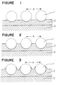
- Figures 1 to 3 show cross sectional diagrammatical views of cases where the fine particles of a polymer are spherical.
- reference numeral 1 indicates fine particles of a polymer
- numeral 2 a thin film layer of a heat resistant polymer
- numeral 3 a substrate
- X an average distance between the centers of the concaves or valleys.
- the fine particles of a polymer are embedded to the film to some extent, followed by heat decomposition to form roughness, as shown in Figures 2 and 3.
- the compound (II) capable of forming a thin film of a heat resistant polymer may be a heat resistant polymer itself or a compound which is capable of forming a heat resistance polymer by e.g. polymerization at the time of the treatment.
- the heat resistant polymer formed by this compound (II) is required to be a material having a heat decomposition temperature higher than the heat decomposition temperature of the fine particles of a polymer. Particularly, it is preferably a material which undergo no chemical or physical change at the time of the heat decomposition of the fine particles of a polymer.
- the heat resistant polymer preferably has a heat decomposition temperature higher by at least 50°C than the heat decomposition temperature of the fine particles of a polymer.
- the compound (II) is the one capable of forming a thin film on the surface of e.g. a substrate at the time of the treatment.
- the compound (II) dissolved or dispersed in the treating agent is required to form a heat resistant polymer thin film by removal of e.g. the solvent at the time of the treatment.
- a solution or a dispersion of a heat resistant polymer itself or a compound capable of being cross-linked to form a heat resistant polymer is used.
- a solution or a dispersion of a compound capable of forming a heat resistant polymer by hydrolysis such as a tetraalkoxysilane or its partial hydrolyzate, may also be used.
- the above-mentioned resin or the silicone resin useful as the material for the fine particles of a polymer may also be employed.
- the most preferred compound (II) is the above-mentioned reactive silane compound and its partial hydrolyzate.
- a reactive silane compound a compound having no hydrophobic group is preferred among compounds of the above-mentioned formulas (A) and (B).
- such a reactive silane compound may have an organic group having a functional group such as an epoxy group or an amino group.
- the most preferred compound is a tetrafunctional reactive silane compound.
- a tetrafunctional reactive silane compound is a compound of the above formula (B) wherein e + g + h is 0, for example, a tetrafunctional reactive silane compound such as a tetraalkoxysilane or a tetraisocyanate silane.
- Y is preferably an alkylene group having at most 6 carbon atoms and containing no fluorine atom.
- a compound of the above formula (B) which contains no hydrophobic group is also preferred.
- a compound of the above formula (A) which contains no hydrophobic group may also be used.
- the compound (II) for forming the second layer is used preferably as diluted with a solvent together with the fine particles of a polymer and a binder, from the viewpoint of the operation efficiency.
- a solvent the above-mentioned organic solvent or the like may be used.
- additives include, for example, fillers such as fine particles of metal such as Sn, In, Al, Zn, Zr, Ti, Sb, Pb, Ta and Si or metal oxides thereof, and surfactants. Their proportions may suitably be from 0.01 to 20 wt% based on the total weight of the compounds (II).
- pretreatment may be conducted as the case requires.
- acid treatment with e.g. diluted hydrofluoric acid or hydrochloric acid
- alkali treatment with e.g. an aqueous sodium hydroxide solution
- discharge treatment by e.g. plasma irradiation, may be conducted.
- the second layer may usually be formed by applying a liquid composed of an organic solvent containing the compound (II) thus prepared, by a usual treating method, such as brush coating, casting, spin coating, dip coating or spray coating, followed by drying in air or in a nitrogen stream under heating.
- a usual treating method such as brush coating, casting, spin coating, dip coating or spray coating
- the fine particles of a polymer will undergo heat decomposition, whereby a roughened surface will be formed.
- the temperature for heating may be determined depending upon the heat resistance of the spherical polymer particles and the substrate.
- the treatment is conducted within a range of from 300 to 800°C.
- the heat decomposition of the fine particles of a polymer by the heat treatment may not be complete, and an adequate effect of the present invention can be obtained even by partial heat decomposition, such that the fine particles of a polymer remain in the interior of the thin film of a heat resistant polymer.
- the thickness of the second layer formed by this surface treatment may be very thin.
- a preferred film thickness is at most 2 ⁇ m like the case of the first layer.
- a too much film thickness is undesirable from the economical viewpoint and from the viewpoint of the scratch resistance and the quality of appearance.
- the degree of roughness of the second layer thus formed and the thicknesses of the respective layers can be optionally controlled by e.g. the concentration of the composition in the liquid containing the composition, the coating conditions, the heating conditions, and the material, the amount and size of the fine particles of a polymer.
- the first layer of the present invention has a relatively low refractive index, whereby low reflecting properties may be imparted. If such an effect is desired, the thickness of the first layer may be adjusted to a thickness where an optical interference will occur. Theoretically, the thickness of the coating film may be at least the thickness of a single molecular layer to obtain water repellency. Taking an economical effect into consideration, the thickness is preferably at most 2 ⁇ m, as mentioned above.
- the substrate there is no particular restriction as to the substrate to which the present invention may be applied.
- a metal, a plastic, glass, ceramic or other inorganic materials, an organic material, or a combination thereof (composite material, laminated material, etc.) may be mentioned.
- the surface of the substrate may, of course, be the substrate surface itself, or may be the surface of a material different from the substrate surface, such as the coating surface of e.g. a coated metal plate, or the surface of a surface-treated layer of e.g. surface-treated glass.
- the shape of the substrate it may not necessarily be a flat plate, and it may have an optional shape depending upon the particular purpose, such as the one having a curvature over the entire surface or at a part thereof.
- a particularly suitable substrate is a substrate made of a transparent material such as glass, and a suitable article is an article having such a substrate mounted to utilize the transparency.
- the substrate of the present invention is particularly suitable for articles for transportation equipments and articles for buildings or building decorations.
- Articles for transportation equipments may be exterior parts such as outer plates, window glasses, mirrors and display panels, and interior parts such as instrument panels, of the transportation equipments such as electric cars, buses, trucks, automobiles, ships or aircrafts, or parts or constituting elements to be used in other transportation equipments.
- the articles for transportation equipments include bodies, window glasses, pantagraphs, etc. of electric cars, bodies, front glasses, side glasses, rear glasses, mirrors, bumpers, etc. of automobiles, buses or trucks, bodies, window glasses, etc. of ships, and bodies, window glasses, etc. of aircrafts.
- Such an article may be composed solely of the surface-treated substrate or may have the surface-treated substrate incorporated therein.
- the former may be a window glass for an automobile, and the latter may be a back mirror for an automobile in which a glass mirror is incorporated.
- the articles for buildings or building decorations may be articles to be attached to buildings or articles already attached to buildings, or articles for buildings which are not attached to buildings but which are used for the buildings, articles for buildings such as furnitures or equipments, and base materials (such as glass plates) constituting such articles.
- window glass plates, window glasses, glass plates for roofs various roofs including glass roofs, glass plates for doors or doors having such glass plates installed, glass plates for partitions, glass plates for green houses, or green houses having such glass plates, transparent plastic plates to be used instead of glass, the above-mentioned various articles for buildings (window materials and roof materials) having such plastic plates incorporated, wall materials made of ceramics, cement, metals or other materials, mirrors, furnitures and display shelves having such walls or mirrors, and glass for showcases.
- Such an article may be made of the surface treated substrate alone or may be the one having the surface treated substrate incorporated therein.
- the former may be a window glass plate, and the latter may be a furniture in which a glass mirror is incorporated.
- the contact angle (°) of a water drop having a size of 1 mm in diameter was measured. Measurements were made at five different points on the surface, and the contact angle was represented by the average value.
- the abrasion test was carried out by the above test method, and the water repellency after the test was evaluated.
- a process comprising ultraviolet irradiation for 8 hours (70°C) and humidity exposure for 4 hours (50 °C) is regarded as one cycle, and the weather resistance was conducted by 200 cycles.
- the weather resistance test was conducted by the above method, and the water repellency after the test was evaluated.
- test sample was immersed in boiling water for one hour. The water repellency after the test was evaluated.
- a container equipped with a stirrer and a thermometer 834.8 g of hexylene glycol were introduced, and then 40.0 g of a dispersion of fine particles of polymethyl methacrylate having an average particle size of 80 nm, 120.5 g of a dispersion of fine particles of tin oxide sol having an average particle size of 5 nm, 62.5 g of ethyl silicate 40 and 62.4 g of a 1 wt% hydrochloric acid aqueous solution were sequentially added thereto. The mixture was stirred at 30 °C for 30 minutes and then left to stand for one day to obtain treating agent 10.
- treating agent 1 On a glass substrate previously polished by cerium oxide and cleaned, treating agent 1 was coated by a flexographic printing method and subjected to heat treatment in a muffle furnace at 600°C for 10 minutes. After the heat treatment, the substrate was withdrawn from the muffle furnace and cooled to room temperature. Then, this substrate was dipped in treating agent 4 and withdrawn therefrom at a rate of 6 cm/min, whereupon it was subjected to heat treatment at 200°C for 30 minutes to obtain a sample test piece. This sample test piece was evaluated, and the results are shown in Table 1.
- treating agent 3 was coated by a spin coating method and subjected to heat treatment in a muffle furnace at 650°C for 10 minutes. After the heat treatment, the substrate was withdrawn from the muffle furnace and cooled to room temperature. Then, this substrate was dipped in treating agent 4 and withdrawn at a rate of 6 cm/min, whereupon it was subjected to heat treatment at 200°C for 30 minutes to obtain a sample test piece. This sample test piece was evaluated, and the results are shown in Table 1.
- treating agent 1 On a glass substrate previously polished by cerium oxide and cleaned, treating agent 1 was coated by a flexographic printing method and subjected to heat treatment in a muffle furnace at 600°C for 10 minutes. After the heat treatment, the substrate was withdrawn from the muffle furnace and cooled to room temperature. Then, to this substrate, treating agent 5 was dropped and coated in the same manner as waxing, followed by drying at room temperature for 60 minutes to obtain a sample test piece. This sample test piece was evaluated, and the results are shown in Table 1.
- treating agent 3 On a glass substrate previously polished by cerium oxide and cleaned, treating agent 3 was coated by a dip coating method and subjected to heat treatment in a muffle furnace at 650°C for 10 minutes. After the heat treatment, the substrate was withdrawn from the muffle furnace and cooled to room temperature. Then, to this substrate, treating agent 5 was dropped and coated in the same manner as waxing, followed by drying at room temperature for 60 minutes to obtain a sample test piece. This sample test piece was evaluated, and the results are shown in Table 1.
- treating agent 3 On a glass substrate previously polished by cerium oxide and cleaned, treating agent 3 was coated by a flexographic printing method and subjected to heat treatment in a muffle furnace at 650°C for 10 minutes. After the heat treatment, the substrate was withdrawn from the muffle furnace and cooled to room temperature. Then, to this substrate, treating agent 7 was dropped and coated in the same manner as waxing, followed by drying at room temperature for 60 minutes to obtain a sample test piece. This sample test piece was evaluated, and the results are shown in Table 1.
- treating agent 6 On a glass substrate previously polished by cerium oxide and cleaned, treating agent 6 was coated by a flexographic printing method and subjected to heat treatment in a muffle furnace at 650°C for 10 minutes. After the heat treatment, the substrate was withdrawn from the muffle furnace and cooled to room temperature. Then, to this substrate, treating agent 8 was dropped and coated in the same manner as waxing, followed by drying at room temperature for 60 minutes to obtain a sample test piece. This sample test piece was evaluated, and the results are shown in Table 1.
- treating agent 6 On a glass substrate previously polished by cerium oxide and cleaned, treating agent 6 was coated by a flexographic printing method and subjected to heat treatment in a muffle furnace at 650°C for 10 minutes. After the heat treatment, the substrate was withdrawn from the muffle furnace and cooled to room temperature. Then, to this substrate, treating agent 9 was dropped and coated in the same manner as waxing, followed by drying at room temperature for 60 minutes to obtain a sample test piece. This sample test piece was evaluated, and the results are shown in Table 1.
- treating agent 2 was coated by a flexographic printing method and subjected to heat treatment in a muffle furnace at 600°C for 10 minutes. After the heat treatment, the substrate was withdrawn from the muffle furnace and cooled to room temperature. Then, this substrate was dipped in treating agent 4 and withdrawn at a rate of 6 cm/min, whereupon it was subjected to heat treatment at 200°C for 30 minutes to obtain a sample test piece. This sample test piece was evaluated, and the results are shown in Table 1.
- the glass products of the present invention had excellent water repellency, adhesion, abrasion resistance and weather resistance.
- Example 4 The test piece prepared in Example 4 was dipped in the reagent as identified in Table 2 for 24 hours, withdrawn and immediately washed, and then the change in appearance and the water repellency of this test piece were evaluated. The results are shown in Table 2.
- Reagent Change in appearance Contact angle (°) Methanol No change 112 Acetone No change 112 Toluene No change 112 Water No change 111 1% sulfuric acid aqueous solution No change 112 1% sodium hydroxide aqueous solution No change 110 Commercial cleanser No change 110 Gasoline No change 112
- Example 5 Treatment of the surface of a laminated front glass for an automobile was conducted in the same manner as in Example 5, and the front glass thus treated was mounted on an automobile.
- automobile was subjected to a running test for 4 hours during day time every day for one month, and the deposition of dust and stain on the surface of the front glass, or in a rainy day, the deposition of water drops, was visually observed every day.
- Example 9 The running test was conducted in the same manner as in Example 9 except that the method of Example 5 was changed to the method of Example 7, whereby the same effects as in Example 9 were confirmed.
- Example 9 The running test was conducted in the same manner as in Example 9 except that the laminated front glass in Example 9 was changed to a side glass or a rear glass, whereby the same effects as in Example 9 were confirmed.
- Example 9 The running test was conducted in the same manner as in Example 9 except that the laminated front glass in Example 9 was changed to a side mirror, whereby the same effects as in Example 9 was confirmed.
- Coating on the surface of a window glass for building was conducted in the same manner as in Example 9 to form a coating film.
- the window glass thus obtained was mounted on a house.
- treating agent 10 was coated by a flexographic printing method and subjected to heat treatment in a muffle furnace at 650°C for 10 minutes. After the heat treatment, the substrate was withdrawn from the muffle furnace and cooled to room temperature. Then, to this substrate, treating agent 7 was dropped and coated in the same manner as waxing, followed by drying at room temperature for 60 minutes to obtain a sample test piece.
- the surface resistance of this sample test piece was 3 ⁇ 10 8 ⁇ / ⁇ as measured by MCP-TESTER, manufactured by Mitsubishi Petrochemical Co., Ltd. Further, the same sample was evaluated, and the results are shown in Table 3. Examples Contact angle (°) Initial Boiling Abrasion resistance Weather resistance Example 14 114 109 104 101
- Example 14 an electrically conductive material is exemplified as the additive.
- the glass product of the present invention provides the equal performance even when the electrically conductive material is substituted by other additives.
- the substrate of the present invention or an article provided therewith exhibits excellent effects as is apparent from the Examples. Namely:
Description


| Examples | Contact angle (°) | |||
| Initial | Boiling | Abrasion resistance | Weather resistance | |
| Example 1 | 110 | 102 | 104 | 100 |
| Example 2 | 110 | 104 | 102 | 102 |
| Example 3 | 114 | 108 | 107 | 107 |
| Example 4 | 115 | 108 | 108 | 106 |
| Example 5 | 117 | 113 | 110 | 110 |
| Example 6 | 117 | 112 | 111 | 110 |
| Example 7 | 115 | 109 | 109 | 108 |
| Comparative Example 1 | 110 | 77 | 30 | 88 |
| Comparative Example 2 | 114 | 82 | 54 | 48 |
| Reagent | Change in appearance | Contact angle (°) |
| Methanol | No change | 112 |
| Acetone | No change | 112 |
| Toluene | No change | 112 |
| Water | No change | 111 |
| 1% sulfuric acid aqueous solution | No change | 112 |
| 1% sodium hydroxide aqueous solution | No change | 110 |
| Commercial cleanser | No change | 110 |
| Gasoline | No change | 112 |
| Examples | Contact angle (°) | |||
| Initial | Boiling | Abrasion resistance | Weather resistance | |
| Example 14 | 114 | 109 | 104 | 101 |
Claims (13)
- A surface-treated substrate consisting essentially of a substrate having at least two treated surface layers wherein the first layer constituting the outermost layer among the treated surface layers is a layer obtained by treating the surface of the second layer with a treating agent containing a compound (I) capable of forming a surface having a contact angle of at least 70° against water, and the second layer constituting an underlayer in contact with the outermost layer is a thin film layer of a heat resistant polymer obtained by treating the surface of the substrate with a treating agent containing a compound (II) capable of forming a thin film of a heat resistant polymer and fine particles of a polymer, thereby forming a thin film and heating said thin film to thermally decompose the fine particles of a polymer.
- The substrate according to Claim 1, wherein the substrate is made of a transparent material.
- The substrate according to Claim 1 or 2, wherein the substrate is made of glass.
- The substrate according to Claim 1, 2 or 3, wherein the substrate is a substrate having at least one film selected from the group consisting of an antistatic film, a transparent electrically conductive film, an electromagnetic wave shielding film, an ultraviolet absorbing film, a heat ray absorbing film and a heat ray reflecting film.
- The substrate according to any one of Claims 1 to 4, wherein the compound (I) is a reactive silane compound having at least one silicon atom having an isocyanate group and/or a hydrolyzable group bonded thereto and at least one hydrophobic group.
- The substrate according to any one of Claims 1 to 5, wherein the compound (I) is at least one reactive silane compound of the following formula (A), (B) or (C) wherein at least one organic group is a hydrophobic group:
- The substrate according to Claim 5 or 6, wherein the hydrophobic group is a polyfluoroorganic group and/or a long chain hydrocarbon group.
- The substrate according to Claim 7, wherein the polyfluoroorganic group is an organic group having a C3-21 perfluoroalkyl moiety or a C2-16 perfluoroalkylene moiety, and the long chain hydrocarbon group is a hydrocarbon group having a C7-30 alkyl moiety or a C7-16 alkylene moiety.
- The substrate according to any one of Claims 1 to 8, wherein the average particle size of the fine particles of a polymer is from 1 to 1,000 nm.
- The substrate according to any one of Claims 1 to 9, wherein the compound (II) is a reactive silane compound having an isocyanate group and/or a hydrolyzable group, and its partial hydrolyzate.
- The substrate according to Claim 10, wherein the compound (II) is a tetraisocyanate silane and/or a tetraalkoxysilane, and its partial hydrolyzate.
- The substrate according to any one of Claims 1 to 11, wherein the treating agent for forming the second layer contains fine particles of a metal and/or a metal oxide.
- A process for producing a substrate having at least two treated surface layers, which comprises treating the surface of a substrate with a treating agent containing a compound (II) capable of forming a thin film of a heat resistant polymer and fine particles of a polymer, thereby forming a thin film, heating said thin film to thermally decompose the fine particles of a polymer to form a thin film layer of a heat resistant polymer, and then treating the surface of the thin film layer of a heat resistant polymer with a treating agent containing a compound (I) capable of forming a surface having a contact angle of at least 70° against water.
Applications Claiming Priority (2)
| Application Number | Priority Date | Filing Date | Title |
|---|---|---|---|
| JP136580/93 | 1993-05-14 | ||
| JP13658093 | 1993-05-14 |
Publications (3)
| Publication Number | Publication Date |
|---|---|
| EP0624404A2 EP0624404A2 (en) | 1994-11-17 |
| EP0624404A3 EP0624404A3 (en) | 1995-02-22 |
| EP0624404B1 true EP0624404B1 (en) | 1998-08-05 |
Family
ID=15178605
Family Applications (1)
| Application Number | Title | Priority Date | Filing Date |
|---|---|---|---|
| EP94107493A Expired - Lifetime EP0624404B1 (en) | 1993-05-14 | 1994-05-13 | Surface-treated substrate and process for its production |
Country Status (3)
| Country | Link |
|---|---|
| US (1) | US5482768A (en) |
| EP (1) | EP0624404B1 (en) |
| DE (1) | DE69412168T2 (en) |
Cited By (1)
| Publication number | Priority date | Publication date | Assignee | Title |
|---|---|---|---|---|
| US9074778B2 (en) | 2009-11-04 | 2015-07-07 | Ssw Holding Company, Inc. | Cooking appliance surfaces having spill containment pattern |
Families Citing this family (54)
| Publication number | Priority date | Publication date | Assignee | Title |
|---|---|---|---|---|
| US5736245A (en) * | 1994-06-17 | 1998-04-07 | Lucent Technologies Inc. | Chemical treatment for silica-containing glass surfaces |
| JPH08143855A (en) * | 1994-09-21 | 1996-06-04 | Asahi Glass Co Ltd | Surface treating composition |
| EP0739919B1 (en) * | 1995-04-25 | 2002-07-24 | Asahi Glass Company Ltd. | Composition for surface treatment |
| US5733519A (en) * | 1996-02-05 | 1998-03-31 | Monsanto Company | Method for producing a dispersible, fine titanium pyrophosphate powder |
| DE69730259T2 (en) * | 1996-03-27 | 2005-09-08 | Asahi Glass Co., Ltd. | Laminate and process for its preparation |
| JP4032444B2 (en) * | 1996-10-11 | 2008-01-16 | 株式会社日立製作所 | Article having super-water-repellent surface capable of controlling light, and printing machine using the same |
| US5786096A (en) * | 1996-11-12 | 1998-07-28 | Asahi Glass Company Ltd. | Surface-treated substrate and process for its production |
| US8653213B2 (en) | 1997-02-03 | 2014-02-18 | Cytonix, Llc | Hydrophobic coating compositions and articles coated with said compositions |
| US6495624B1 (en) | 1997-02-03 | 2002-12-17 | Cytonix Corporation | Hydrophobic coating compositions, articles coated with said compositions, and processes for manufacturing same |
| US6156389A (en) | 1997-02-03 | 2000-12-05 | Cytonix Corporation | Hydrophobic coating compositions, articles coated with said compositions, and processes for manufacturing same |
| US7268179B2 (en) | 1997-02-03 | 2007-09-11 | Cytonix Corporation | Hydrophobic coating compositions, articles coated with said compositions, and processes for manufacturing same |
| US6251469B1 (en) | 1997-03-19 | 2001-06-26 | International Business Machines, Corporation | Method of rendering a substrate selectively non-wettable chip carrier with enhanced wire bondability |
| EP0891953B1 (en) * | 1997-07-15 | 2006-01-11 | Central Glass Company, Limited | Glass plate with water-repellent film and method for producing same |
| ES2234145T3 (en) | 1997-09-12 | 2005-06-16 | Asahi Glass Company Ltd. | COMPOSITION OF SURFACE TREATMENT, SURFACE TREATMENT PROCEDURE, SUBSTRATE AND ARTICLE. |
| DE19917151A1 (en) * | 1999-04-16 | 2000-10-19 | Miele & Cie | Production of polymer coating for utensil baskets for dish washers comprises melt coating to yield rough or uneven surface |
| US6399688B1 (en) * | 1999-10-04 | 2002-06-04 | Shigeki Iida | Coating composition and coating method |
| US6692835B1 (en) | 2000-09-14 | 2004-02-17 | R. J. Reynolds Tobacco Company | Innerwrap with polyvinyl alcohol slip coating |
| EP1193185A1 (en) * | 2000-10-02 | 2002-04-03 | Heineken Technical Services B.V. | Glass container with improved coating |
| JP2003211084A (en) * | 2001-10-26 | 2003-07-29 | Seiko Instruments Inc | Method for applying fluorocarbon resin, sliding member using the method and gas compressor |
| WO2004043853A1 (en) * | 2002-11-13 | 2004-05-27 | Nippon Soda Co., Ltd. | Dispersoid having metal-oxygen bond, metal oxide film, and monomolecular film |
| US7452574B2 (en) * | 2003-02-27 | 2008-11-18 | Molecular Imprints, Inc. | Method to reduce adhesion between a polymerizable layer and a substrate employing a fluorine-containing layer |
| US20040168613A1 (en) * | 2003-02-27 | 2004-09-02 | Molecular Imprints, Inc. | Composition and method to form a release layer |
| US7157036B2 (en) * | 2003-06-17 | 2007-01-02 | Molecular Imprints, Inc | Method to reduce adhesion between a conformable region and a pattern of a mold |
| US7307118B2 (en) * | 2004-11-24 | 2007-12-11 | Molecular Imprints, Inc. | Composition to reduce adhesion between a conformable region and a mold |
| US20050160934A1 (en) * | 2004-01-23 | 2005-07-28 | Molecular Imprints, Inc. | Materials and methods for imprint lithography |
| US20050069714A1 (en) * | 2003-09-30 | 2005-03-31 | Hart Terence J. | Method and compositions for improving durability of coated or decorated ceramic substrates |
| US20050084804A1 (en) * | 2003-10-16 | 2005-04-21 | Molecular Imprints, Inc. | Low surface energy templates |
| EP1564263A1 (en) * | 2004-01-30 | 2005-08-17 | Arkema | A thermoplastic based powder and its use to obtain a rough coating |
| US8076386B2 (en) * | 2004-02-23 | 2011-12-13 | Molecular Imprints, Inc. | Materials for imprint lithography |
| US20060062922A1 (en) * | 2004-09-23 | 2006-03-23 | Molecular Imprints, Inc. | Polymerization technique to attenuate oxygen inhibition of solidification of liquids and composition therefor |
| US7292326B2 (en) * | 2004-11-30 | 2007-11-06 | Molecular Imprints, Inc. | Interferometric analysis for the manufacture of nano-scale devices |
| US20060266916A1 (en) * | 2005-05-25 | 2006-11-30 | Molecular Imprints, Inc. | Imprint lithography template having a coating to reflect and/or absorb actinic energy |
| US8808808B2 (en) | 2005-07-22 | 2014-08-19 | Molecular Imprints, Inc. | Method for imprint lithography utilizing an adhesion primer layer |
| US7759407B2 (en) * | 2005-07-22 | 2010-07-20 | Molecular Imprints, Inc. | Composition for adhering materials together |
| US8557351B2 (en) | 2005-07-22 | 2013-10-15 | Molecular Imprints, Inc. | Method for adhering materials together |
| US20070141305A1 (en) * | 2005-12-21 | 2007-06-21 | Toshihiro Kasai | Superhydrophobic coating |
| HUE028612T2 (en) * | 2006-08-09 | 2017-01-30 | Innovation Chemical Tech Ltd | Nano structured phased hydrophobic layers on substrates |
| US20080110557A1 (en) * | 2006-11-15 | 2008-05-15 | Molecular Imprints, Inc. | Methods and Compositions for Providing Preferential Adhesion and Release of Adjacent Surfaces |
| US8741158B2 (en) | 2010-10-08 | 2014-06-03 | Ut-Battelle, Llc | Superhydrophobic transparent glass (STG) thin film articles |
| US11292919B2 (en) * | 2010-10-08 | 2022-04-05 | Ut-Battelle, Llc | Anti-fingerprint coatings |
| US11497681B2 (en) | 2012-02-28 | 2022-11-15 | Corning Incorporated | Glass articles with low-friction coatings |
| US10737973B2 (en) | 2012-02-28 | 2020-08-11 | Corning Incorporated | Pharmaceutical glass coating for achieving particle reduction |
| EP2819843B1 (en) | 2012-02-28 | 2021-09-01 | Corning Incorporated | Pharmaceutical packages comprising glass articles with low-friction coatings |
| US10273048B2 (en) | 2012-06-07 | 2019-04-30 | Corning Incorporated | Delamination resistant glass containers with heat-tolerant coatings |
| US9034442B2 (en) | 2012-11-30 | 2015-05-19 | Corning Incorporated | Strengthened borosilicate glass containers with improved damage tolerance |
| US10117806B2 (en) | 2012-11-30 | 2018-11-06 | Corning Incorporated | Strengthened glass containers resistant to delamination and damage |
| JP6221387B2 (en) * | 2013-06-18 | 2017-11-01 | 日亜化学工業株式会社 | Light emitting device and manufacturing method thereof |
| US9637658B2 (en) | 2013-06-24 | 2017-05-02 | The Boeing Company | Coatings, coating compositions, and methods of delaying ice formation |
| US20150239773A1 (en) | 2014-02-21 | 2015-08-27 | Ut-Battelle, Llc | Transparent omniphobic thin film articles |
| KR102270650B1 (en) | 2014-09-05 | 2021-06-30 | 코닝 인코포레이티드 | Glass Articles and Methods for Improving the Reliability of Glass Articles |
| WO2016085867A1 (en) | 2014-11-26 | 2016-06-02 | Corning Incorporated | Methods for producing strengthened and durable glass containers |
| EP3150564B1 (en) | 2015-09-30 | 2018-12-05 | Corning Incorporated | Halogenated polyimide siloxane chemical compositions and glass articles with halogenated polylmide siloxane low-friction coatings |
| US20170121058A1 (en) | 2015-10-30 | 2017-05-04 | Corning Incorporated | Glass articles with mixed polymer and metal oxide coatings |
| CN108906550A (en) * | 2018-09-04 | 2018-11-30 | 中国工程物理研究院化工材料研究所 | There is lyophoby characteristic to complicated liquid phase and eliminate the preparation method on buildup of static electricity surface |
Family Cites Families (8)
| Publication number | Priority date | Publication date | Assignee | Title |
|---|---|---|---|---|
| JPS5926944A (en) * | 1982-08-04 | 1984-02-13 | Asahi Glass Co Ltd | Glass of low reflectance |
| JPS6140845A (en) * | 1984-07-31 | 1986-02-27 | Asahi Glass Co Ltd | Low reflectance glass |
| US4734295A (en) * | 1985-01-07 | 1988-03-29 | Liu P Dong Guang | Glare control |
| DE3528181A1 (en) * | 1985-08-06 | 1987-02-12 | Rossbach Volker Prof Dr | METHOD FOR MODIFYING THE SURFACE OF POLYTETRAFLUORETHYLENE |
| JPH0668084B2 (en) * | 1986-09-01 | 1994-08-31 | 川鉄テクノリサ−チ株式会社 | Manufacturing method of surface hydrophobic metal material |
| JP2815595B2 (en) * | 1988-12-27 | 1998-10-27 | 松本製薬工業株式会社 | Prevention of elution of alkali etc. by treating metal oxide on the inner surface of medical glassware |
| DE69229924T2 (en) * | 1991-05-17 | 1999-12-23 | Asahi Glass Co Ltd | Surface treated substrate |
| JP2901441B2 (en) * | 1992-10-28 | 1999-06-07 | 日本電気アイシーマイコンシステム株式会社 | Buffer amplifier |
-
1994
- 1994-05-13 US US08/242,675 patent/US5482768A/en not_active Expired - Fee Related
- 1994-05-13 EP EP94107493A patent/EP0624404B1/en not_active Expired - Lifetime
- 1994-05-13 DE DE69412168T patent/DE69412168T2/en not_active Expired - Fee Related
Cited By (1)
| Publication number | Priority date | Publication date | Assignee | Title |
|---|---|---|---|---|
| US9074778B2 (en) | 2009-11-04 | 2015-07-07 | Ssw Holding Company, Inc. | Cooking appliance surfaces having spill containment pattern |
Also Published As
| Publication number | Publication date |
|---|---|
| DE69412168T2 (en) | 1998-12-10 |
| EP0624404A3 (en) | 1995-02-22 |
| DE69412168D1 (en) | 1998-09-10 |
| EP0624404A2 (en) | 1994-11-17 |
| US5482768A (en) | 1996-01-09 |
Similar Documents
| Publication | Publication Date | Title |
|---|---|---|
| EP0624404B1 (en) | Surface-treated substrate and process for its production | |
| EP0759413B1 (en) | Surface-treated substrate | |
| EP0703282B1 (en) | Composition for surface treatment | |
| US5976702A (en) | Composition for surface treatment | |
| US5576109A (en) | Surface treating agent and surface-treated substrate | |
| EP1022323B1 (en) | Surface treatment composition, method of surface treatment, substrate, and article | |
| US6599634B2 (en) | Fluorine-containing organic silicon compound, water repellent composition containing it, and surface-treated substrate and process for its production | |
| US5786096A (en) | Surface-treated substrate and process for its production | |
| JP3315004B2 (en) | Surface-treated substrate and method for producing the same | |
| EP1103531B1 (en) | Substrate having treated surface layers and process for producing it | |
| JP4706097B2 (en) | Substrate having surface treatment layer and method for producing the same | |
| JP3210045B2 (en) | Surface treated substrate | |
| EP1101747B1 (en) | Substrate having treated surface layers and process for producing it | |
| JPH11116943A (en) | Surface treating agent, treated substrate, article, and fluorine-containing organosilicon compound | |
| JP2000129247A (en) | Surface treatment agent, surface treating agent composition, surface treatment method, and substrate treated therewith | |
| JPH11181412A (en) | Surface treatment agent and base material treated therewith | |
| JPH0827456A (en) | Surface traeting agent and base subjected to surface treatment | |
| JPH10180937A (en) | Surface-treated base material and manufacture of the same | |
| JPH07166122A (en) | Base material and article having stainproofing properties | |
| JP3629755B2 (en) | Surface-treated substrate and method for producing the same | |
| JP3308282B2 (en) | Building and construction goods | |
| JP3181310B2 (en) | Surface treatment agent for transportation equipment | |
| JPH1180667A (en) | Surface treatment, surface treatment composition and surface-treated substrate board | |
| JPH0718253A (en) | Surface-treated base material | |
| JPH0718252A (en) | Base material having surface-treated layer |
Legal Events
| Date | Code | Title | Description |
|---|---|---|---|
| PUAI | Public reference made under article 153(3) epc to a published international application that has entered the european phase |
Free format text: ORIGINAL CODE: 0009012 |
|
| AK | Designated contracting states |
Kind code of ref document: A2 Designated state(s): BE DE FR GB |
|
| PUAL | Search report despatched |
Free format text: ORIGINAL CODE: 0009013 |
|
| AK | Designated contracting states |
Kind code of ref document: A3 Designated state(s): BE DE FR GB |
|
| 17P | Request for examination filed |
Effective date: 19950801 |
|
| 17Q | First examination report despatched |
Effective date: 19961219 |
|
| GRAG | Despatch of communication of intention to grant |
Free format text: ORIGINAL CODE: EPIDOS AGRA |
|
| GRAG | Despatch of communication of intention to grant |
Free format text: ORIGINAL CODE: EPIDOS AGRA |
|
| GRAG | Despatch of communication of intention to grant |
Free format text: ORIGINAL CODE: EPIDOS AGRA |
|
| GRAH | Despatch of communication of intention to grant a patent |
Free format text: ORIGINAL CODE: EPIDOS IGRA |
|
| GRAH | Despatch of communication of intention to grant a patent |
Free format text: ORIGINAL CODE: EPIDOS IGRA |
|
| GRAA | (expected) grant |
Free format text: ORIGINAL CODE: 0009210 |
|
| AK | Designated contracting states |
Kind code of ref document: B1 Designated state(s): BE DE FR GB |
|
| REF | Corresponds to: |
Ref document number: 69412168 Country of ref document: DE Date of ref document: 19980910 |
|
| ET | Fr: translation filed | ||
| PLBE | No opposition filed within time limit |
Free format text: ORIGINAL CODE: 0009261 |
|
| STAA | Information on the status of an ep patent application or granted ep patent |
Free format text: STATUS: NO OPPOSITION FILED WITHIN TIME LIMIT |
|
| 26N | No opposition filed | ||
| REG | Reference to a national code |
Ref country code: FR Ref legal event code: CA |
|
| REG | Reference to a national code |
Ref country code: GB Ref legal event code: IF02 |
|
| PGFP | Annual fee paid to national office [announced via postgrant information from national office to epo] |
Ref country code: DE Payment date: 20050506 Year of fee payment: 12 |
|
| PGFP | Annual fee paid to national office [announced via postgrant information from national office to epo] |
Ref country code: GB Payment date: 20050511 Year of fee payment: 12 Ref country code: FR Payment date: 20050511 Year of fee payment: 12 |
|
| PGFP | Annual fee paid to national office [announced via postgrant information from national office to epo] |
Ref country code: BE Payment date: 20050714 Year of fee payment: 12 |
|
| PG25 | Lapsed in a contracting state [announced via postgrant information from national office to epo] |
Ref country code: GB Free format text: LAPSE BECAUSE OF NON-PAYMENT OF DUE FEES Effective date: 20060513 |
|
| PG25 | Lapsed in a contracting state [announced via postgrant information from national office to epo] |
Ref country code: BE Free format text: LAPSE BECAUSE OF NON-PAYMENT OF DUE FEES Effective date: 20060531 |
|
| PG25 | Lapsed in a contracting state [announced via postgrant information from national office to epo] |
Ref country code: DE Free format text: LAPSE BECAUSE OF NON-PAYMENT OF DUE FEES Effective date: 20061201 |
|
| GBPC | Gb: european patent ceased through non-payment of renewal fee |
Effective date: 20060513 |
|
| REG | Reference to a national code |
Ref country code: FR Ref legal event code: ST Effective date: 20070131 |
|
| BERE | Be: lapsed |
Owner name: *ASAHI GLASS CY LTD Effective date: 20060531 |
|
| PG25 | Lapsed in a contracting state [announced via postgrant information from national office to epo] |
Ref country code: FR Free format text: LAPSE BECAUSE OF NON-PAYMENT OF DUE FEES Effective date: 20060531 |