EP0667936B1 - Method of fabricating a compound part being secure against rotation and insert ejection by pressing an insert into a sheet metal and inserts usable therefore - Google Patents
Method of fabricating a compound part being secure against rotation and insert ejection by pressing an insert into a sheet metal and inserts usable therefore Download PDFInfo
- Publication number
- EP0667936B1 EP0667936B1 EP93915638A EP93915638A EP0667936B1 EP 0667936 B1 EP0667936 B1 EP 0667936B1 EP 93915638 A EP93915638 A EP 93915638A EP 93915638 A EP93915638 A EP 93915638A EP 0667936 B1 EP0667936 B1 EP 0667936B1
- Authority
- EP
- European Patent Office
- Prior art keywords
- insertion part
- longitudinal axis
- shank
- sheet metal
- screw
- Prior art date
- Legal status (The legal status is an assumption and is not a legal conclusion. Google has not performed a legal analysis and makes no representation as to the accuracy of the status listed.)
- Expired - Lifetime
Links
- 239000002184 metal Substances 0.000 title claims abstract description 31
- 238000003825 pressing Methods 0.000 title claims abstract description 8
- 238000004519 manufacturing process Methods 0.000 title description 3
- 150000001875 compounds Chemical group 0.000 title 1
- 238000000034 method Methods 0.000 claims abstract description 29
- 239000000463 material Substances 0.000 claims description 30
- 238000003780 insertion Methods 0.000 claims description 18
- 230000037431 insertion Effects 0.000 claims description 18
- 239000002131 composite material Substances 0.000 claims description 10
- 239000007769 metal material Substances 0.000 claims description 7
- 238000009825 accumulation Methods 0.000 claims description 4
- 230000007704 transition Effects 0.000 claims description 4
- 230000001154 acute effect Effects 0.000 claims description 3
- 239000011324 bead Substances 0.000 claims description 3
- 238000005299 abrasion Methods 0.000 claims description 2
- 230000000284 resting effect Effects 0.000 claims 5
- 230000008569 process Effects 0.000 abstract description 14
- 238000005304 joining Methods 0.000 description 12
- 230000006835 compression Effects 0.000 description 6
- 238000007906 compression Methods 0.000 description 6
- 238000006073 displacement reaction Methods 0.000 description 5
- 238000005096 rolling process Methods 0.000 description 3
- 230000008901 benefit Effects 0.000 description 2
- 230000000694 effects Effects 0.000 description 2
- 238000009434 installation Methods 0.000 description 2
- 238000004080 punching Methods 0.000 description 2
- 230000008439 repair process Effects 0.000 description 2
- XLYOFNOQVPJJNP-UHFFFAOYSA-N water Substances O XLYOFNOQVPJJNP-UHFFFAOYSA-N 0.000 description 2
- 230000003313 weakening effect Effects 0.000 description 2
- 239000000969 carrier Substances 0.000 description 1
- 239000011248 coating agent Substances 0.000 description 1
- 238000000576 coating method Methods 0.000 description 1
- 238000005260 corrosion Methods 0.000 description 1
- 230000007797 corrosion Effects 0.000 description 1
- 238000005553 drilling Methods 0.000 description 1
- 230000006872 improvement Effects 0.000 description 1
- 230000002093 peripheral effect Effects 0.000 description 1
- 230000008092 positive effect Effects 0.000 description 1
- 238000002360 preparation method Methods 0.000 description 1
- 238000007493 shaping process Methods 0.000 description 1
Images


Classifications
-
- B—PERFORMING OPERATIONS; TRANSPORTING
- B23—MACHINE TOOLS; METAL-WORKING NOT OTHERWISE PROVIDED FOR
- B23P—METAL-WORKING NOT OTHERWISE PROVIDED FOR; COMBINED OPERATIONS; UNIVERSAL MACHINE TOOLS
- B23P19/00—Machines for simply fitting together or separating metal parts or objects, or metal and non-metal parts, whether or not involving some deformation; Tools or devices therefor so far as not provided for in other classes
- B23P19/04—Machines for simply fitting together or separating metal parts or objects, or metal and non-metal parts, whether or not involving some deformation; Tools or devices therefor so far as not provided for in other classes for assembling or disassembling parts
- B23P19/06—Screw or nut setting or loosening machines
- B23P19/062—Pierce nut setting machines
-
- F—MECHANICAL ENGINEERING; LIGHTING; HEATING; WEAPONS; BLASTING
- F16—ENGINEERING ELEMENTS AND UNITS; GENERAL MEASURES FOR PRODUCING AND MAINTAINING EFFECTIVE FUNCTIONING OF MACHINES OR INSTALLATIONS; THERMAL INSULATION IN GENERAL
- F16B—DEVICES FOR FASTENING OR SECURING CONSTRUCTIONAL ELEMENTS OR MACHINE PARTS TOGETHER, e.g. NAILS, BOLTS, CIRCLIPS, CLAMPS, CLIPS OR WEDGES; JOINTS OR JOINTING
- F16B37/00—Nuts or like thread-engaging members
- F16B37/04—Devices for fastening nuts to surfaces, e.g. sheets, plates
- F16B37/06—Devices for fastening nuts to surfaces, e.g. sheets, plates by means of welding or riveting
- F16B37/062—Devices for fastening nuts to surfaces, e.g. sheets, plates by means of welding or riveting by means of riveting
- F16B37/068—Devices for fastening nuts to surfaces, e.g. sheets, plates by means of welding or riveting by means of riveting by deforming the material of the support, e.g. the sheet or plate
-
- Y—GENERAL TAGGING OF NEW TECHNOLOGICAL DEVELOPMENTS; GENERAL TAGGING OF CROSS-SECTIONAL TECHNOLOGIES SPANNING OVER SEVERAL SECTIONS OF THE IPC; TECHNICAL SUBJECTS COVERED BY FORMER USPC CROSS-REFERENCE ART COLLECTIONS [XRACs] AND DIGESTS
- Y10—TECHNICAL SUBJECTS COVERED BY FORMER USPC
- Y10T—TECHNICAL SUBJECTS COVERED BY FORMER US CLASSIFICATION
- Y10T29/00—Metal working
- Y10T29/49—Method of mechanical manufacture
- Y10T29/49826—Assembling or joining
- Y10T29/49908—Joining by deforming
- Y10T29/49925—Inward deformation of aperture or hollow body wall
- Y10T29/49934—Inward deformation of aperture or hollow body wall by axially applying force
Definitions
- the invention relates to a method of the type mentioned in the preamble of claim 1.
- Press-fit parts intended for such a method can be a bolt or a screw or also an internal thread carrier effective in the manner of a nut.
- Press-in parts of the type mentioned in the form of a press-in screw are, for example, the subject of D-C-25 45 581.
- press-in nuts they are known, for example, from the specialist journal "DRAHTWELT" 5-1975, p. 173.
- press-in parts of the type mentioned above After being pressed into a sheet metal to form a composite part, press-in parts of the type mentioned above no longer need a counter-holder for screwing on a nut or screwing in a threaded bolt. This means that installation is also considerably easier for repairs. There are also applications in which the press-in part is no longer accessible to a counterholder after installation.
- a disadvantage of a composite part containing a press-in screw of the known type is that the press-in screw has only a limited minimum clamping length.
- the clamping length corresponds to the distance between the contact surface of the screw head and the threaded end of the head of an internal thread carrier screwed onto the screw shaft. This minimum clamping length is reduced by four lengths in the case of the press screw mentioned at the beginning. Two of these length sections serve to prevent rotation and expressness.
- the security against rotation is formed in the above-mentioned screw by a collar attached to the screw head and projecting beyond the shaft diameter with radially projecting arms which embed themselves in the flat material during compression, so that this flows into spaces between the arms (DE-C-25 45 581).
- the safety against squeezing out is achieved by an annular recess below this collar, which serves to prevent rotation, into which the flat material displaced by the radial arms is pressed.
- a calibration collar and a conventional thread run-out then connect to the ring recess. So that the ring recess can be filled with a sufficient amount of displaced material to ensure the safety against squeezing out, the dimensions of the radial arms and the ring recess must be matched to the respective sheet thickness. Depending on the thickness of the sheet to be processed, different screws must be provided. The disadvantages for warehousing and logistics are obvious.
- the press-out locking that is to say the fixing in the axial direction, is carried out by material displacement in an undercut area.
- a circumferential ring projection protruding in the axial direction serves as a displacement element on the underside of the head of the press-in part.
- a composite part is known from US-A-3 253 631, the press-in part of which essentially also has the features of the press-in part described in the preamble of claim 1 and used in the method according to the invention, but with its shaft part immediately prior to the joining process the perforation of the sheet itself punched out.
- the contact surface of the sheet which is effective as a counter-holder during the punching and joining process, is provided in its area surrounding the hole edge with an annular collar projecting in the direction of the press-in part, which presses the hole edge of the sheet into the annular space and into a positive connection with the form projections during the joining process.
- the edge of the hole is pressed out of the original sheet metal plane in the axial direction of the press-in part.
- the manufacturing method of a composite part containing a rivet nut is known with essential features of the preamble of claim 1.
- the sheet material is pressed into the annular groove of a neck part of a press-in nut to be inserted into the opening of a sheet by a displacement process.
- the head part is pressed into the sheet surface during the press-in process, the sheet material displaced thereby flowing into the annular groove.
- the thickness of the hole edge area which is decisive for the safety against squeezing is thereby reduced at the expense of the safety against squeezing out of the press-in nut.
- the known method should therefore hardly be applicable even with very thin sheets.
- the invention has for its object to provide composite parts of the type mentioned with good resistance to twisting and squeezing, which do not have the disadvantages of the prior art, in particular with the same dimensions with flat material of different wall thicknesses can be pressed in the same way and in their embodiment as Insert screws have a comparatively larger screw-in or clamping length.
- This object is achieved by a method with the features of claims 1 to 3 and with press-in parts used for this purpose according to claims 4 to 15.
- the press-in part is designed as a screw or bolt is the shaping of the shaft-side flank of the annular space caused by compression by the adjacent rolling of an annular groove concentric with the longitudinal axis into the shaft if the inner diameter of the annular groove is smaller than the thread core diameter of an internal thread carrier to be screwed on or one nut to be screwed on. Then this ring groove serves as the head-side thread runout of the external thread.
- the flat material is provided with a perforation which has the shape of a neck collar protruding from its flat plane Neck width has an internal diameter sufficient for the shaft to be passed through.
- material accumulates in the peripheral region of the shaft. This material accumulated there is available during the press-in process for the press-fit into the annular space located between the shaft part and the head part and thus ensures the desired safety against squeezing to a particularly high degree. As a result, no flow deformation caused by a material displacement process is required to penetrate the flat material into the annular space.
- the flat material essentially retains its original thickness and is therefore not weakened, as is the case with the press-in parts according to the prior art, in the area which is crucial for the safety against squeezing out and, in the case of thin sheets, for the overall stability of the joint connection.
- This advantageous effect is further improved when the perforated edge of the neck collar is bent inwards in an approximately radial direction to the longitudinal axis of the press-in part. In this case, the material accumulation in the area around the hole is increased again.
- the pressing-in of the press-in part is facilitated, since the edge of the hole in the neck collar is already radially aligned and does not have to be bent into this alignment by applying pressure force.
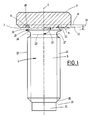
- the press-in part shown in Fig. 1 is designed as a press-in screw. It is briefly referred to below as "screw" 1.
- the screw 1 contains, arranged around a common longitudinal axis 2, a screw head 3 of larger diameter with a bearing surface 4 which is essentially radial with respect to the longitudinal axis 2 and a shaft 5 of smaller diameter projecting on one side in the axial direction beyond the bearing surface 4 and concentric with the longitudinal axis 2.
- a constriction annular space 6 which is concentric with the longitudinal axis 2 and is open radially outward is arranged in the transition region between screw head 3 and shaft 5.
- This constriction is used for the joint connection Screw 1 with a flat material (hereinafter referred to as "sheet") as an annular space 6 for receiving the sheet material.
- sheet a flat material
- the annular space 6 extends from the shaft side from an area 7 not surrounded by the screw head 3 in the axial direction to the plane 4 ′ spanned by the head support surface 4. Outside the shank diameter and distributed over the circumference of the head, protrusions 8 of long bulges protrude from the support surface 4. These are embedded in the sheet metal 9 (FIG. 4 et seq.) In the joining state and, by absorbing torque, ensure that they are secured against rotation relative to the sheet 9.
- the annular space 6 extends to the plane 4 ′ spanned by the bearing surface 4.
- the bearing surface 4 does not run at right angles to the longitudinal axis 2, as shown in FIG. 1, but instead forms an acute angle converging with the top of the screw head 3.
- the contact surface 4 is part of a conical surface. If there is talk above of the top and below of the bottom of the head part of a press-in part, this means nothing about the absolute position of the press-in part in the joined state. Rather, the top side is to be understood to mean the side of the head part facing away from the flat material in the joined state and the bottom side facing the flat material. The annular space 6 can then reach this conical surface or extend beyond it into the screw head 3.
- the annular space 6 has the cross-sectional shape of approximately a gutter with a rounded gutter bottom 10.
- the central axis 11 of the channel shape forms an angle ⁇ of approximately 90 ° with the longitudinal axis 2.
- the channel shape can also be such that its central axis 11 forms with the longitudinal axis 2 a slightly acute angle ⁇ converging towards the top of the screw head.
- the shaped projections 8 protrude from the support surface 4 in the manner of long beads and extend approximately radially to the longitudinal axis 2.
- the shaped projections are at the same circumferential distances on the circumference of the head distributed and extend almost over the entire width of the support surface.
- an annular projection 15 projecting in the radial direction is arranged at a distance 14 from the contact surface 4. It has a tapering, approximately wedge-shaped cross-sectional shape.
- the head-side flank 16 of the ring projection 15 forms the shaft-side flank of the annular space 6.
- the ring projection 15 projects beyond the circumference of the shaft 5 in the radial direction.
- the shaft 5 has an annular groove 17 with a U-shaped cross-sectional shape.
- the shaft-side flank 18 of the ring projection 15 forms the head-side U-leg of the ring groove 17.
- the other U-leg of the ring groove 17, on the other hand, forms the thread runout of the thread 12 close to the head.
- the central axis 23 of the U-shaped cross-sectional shape of the ring groove 17 runs approximately at right angles to the longitudinal axis 2.
- the free end 19 of the shaft 5 merges with a shoulder 20 forming the thread-side thread runout of the thread 12 into an end piece 21 with a smaller diameter.
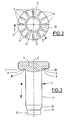
- a blank of a screw 1 is shown.
- the underside of the screw head already has the shape projections 8 produced by compression.
- a thread 12 and the annular groove 17 are rolled into the shaft.
- the latter causes material of the shaft 5 to be displaced in the direction of the screw head 3 and thereby grows up in the radial direction.
- the annular projection 15 is formed, the flank 16 rounded off in the manner of a fillet forms the flank of the annular space 6 on the shaft side.
- the inner diameter of the annular groove 17 is dimensioned such that it is smaller than the thread core diameter of an internal thread carrier to be screwed on.
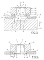
- FIGS. 4 to 7 The individual process steps for pressing a screw according to the invention into a sheet 9 are shown in FIGS. 4 to 7.
- the sheet is first prepared by assigning it to a screw 1 and having a neck collar 22 Holes 24 is provided.
- a hole is first made in the sheet metal by punching or drilling and then the edge of the hole 25 is crimped into a neck collar 22. This can extend out of the sheet metal surface in the direction of insertion 26 of the screw 1 or, as shown in FIG. 4, against this direction.
- An alternative embodiment of the neck collar 22 is shown in FIG. 6.
- the perforated edge 25 of the neck collar 22 is here bent inward in approximately radial direction to the longitudinal axis 2, so that the perforated wall 27 extends approximately in a cylindrical jacket surface arranged concentrically to the longitudinal axis 2.
- the advantage of this configuration is, on the one hand, an increased material accumulation in the hole edge area.
- the effort required to produce the joint connection is reduced compared to the neck collar configuration according to FIG. 4, since less deformation work has to be carried out. This has a positive effect on tool life.
- the hole diameter 28 is dimensioned such that the screw 1 can be inserted into the hole 24 without abrasion. In the case of surface-coated screws, this can be done without damaging their coating.
- the joint connection between screw 1 and sheet 9 is made as follows:
- the screw head is acted upon in the direction of arrow 29 (FIG. 5) with a press ram (not shown).
- a male part 30 in the form of a hollow cylinder serves as the counter-tool, the end face 31 thereof facing the screw head 3 serves as a support surface for the sheet 9 or as a counter surface for the press ram.
- the neck collar 22 is deformed back into the sheet metal plane 32.
- the hole diameter 28 is thereby reduced, as a result of which the hole wall 27 is pressed onto the shaft region adjoining the underside of the screw head 3.
- Sheet metal material flows into the annular space 6 and fills it almost completely.
- the molded projections 8 of the bearing surface 4 penetrate completely into the sheet.
- the neck collar 22 which originally protrudes from the sheet metal plane is deformed back so far that it runs practically completely in the sheet metal plane 32.
- electrical connecting parts for example eyelets of earth cables
- the joint connection according to the invention has a high torsional strength even with the thinnest sheets, the thickness of which is even less than the distance 14. This is particularly advantageous when unscrewing nuts with increased screwing torque or when removing corroded connections in the event of a repair.
- a decisive factor for the safety against squeezing is the shear cross section 33, that is to say the width of the annular space 6 in the axial direction. Due to the fact that the molded projections 8 are arranged on the underside of the screw head 3 outside the annular space 6, there is no weakening of the shear cross-section 33 which is effective in the axial direction and thus of the squeeze-out strength of the joint connection.
- annular projection 15 which bulges when the annular groove 17 is rolled in is prevented from further radial expansion by a form rolling which acts radially inward on it.
- the excess material is inevitably diverted in a direction not acted upon by the rolling tool, that is to say in the direction of the screw head 3.
- this ridge leads to an even more effective form-fit engagement in the carrier plate when the shaft is later loaded in the direction of approximately the plate plane 32.
- Fig. 9 shows an embodiment of a screw according to the invention with a countersunk head 35.
- the underside of the screw runs in a conical surface area converging in the direction of the shaft.
- Long-bead-like shaped projections 8 protrude from the support surface 4, which extend in the radial direction over almost the entire width of the support surface 4 and are distributed at equal intervals on the circumference of the head.
- FIGS. 10 to 12 Another embodiment of a screw according to the invention is shown in FIGS. 10 to 12.
- This screw has an additional shaft part 36 projecting from its upper side in the axial direction and concentric with the longitudinal axis 2.
- annular space 37 which is concentric with the longitudinal axis 2, for accommodating sheet metal material is arranged.
- the design of this annular space 37 corresponds to that of the aforementioned annular space 6.
- Such screws are thus pressed with their top side into a carrier plate.
- the preparation of the sheet and the press-in process go as in the embodiment according to Fig. 4 to Fig. 7.
- the advantage of this embodiment lies primarily in the fact that the underside of the screw head 3, which in this case faces away from the sheet metal in the joining state, is available as a defined plan contact surface, for example for electrical connecting eyes. In the case of such electrical connecting elements, the greatest possible plan support should be sought with regard to good electrical contacting.
- FIGS. 13 to 17 relate to a press-in part designed as an internal thread carrier, hereinafter referred to as "nut" 38.
- the nut 38 essentially contains a head part 39 of larger diameter and a hollow shaft 40 protruding from the underside of the head part 39, arranged around a common longitudinal axis 2.
- a through hole 41 with an internal thread 44 extends through the head part 39 and the hollow shaft 40.
- the hollow shaft indicates an inner countersink 43 on its free end 42.
- the free end 42 of the hollow shaft 40 is also expanded, i.e. its outer diameter increases continuously from the underside of the head part 39 to the free end 42.
- annular space 37 approximately corresponding to the above-described annular space 6 is created in the transition region between the head part 39 and the hollow shaft 40 for receiving the material of a sheet metal in the joined state.
- protrude long bead-like projections 8 which extend in the radial direction almost over the entire width of the contact surface 4 of the head part 39 and are distributed at equal intervals over its circumference.
- FIGS. 15 to 17 The production of a nut according to the invention is shown schematically in the sequence of representations from FIGS. 15 to 17.
- the mother blank shown in FIG. 15 has an underside which is already formed by, for example, compression.
- Its hollow shaft 40 is provided with an internal countersink 43, but has not yet been expanded.
- the hollow shaft is widened and maintained by a compression acting on the free end 42 of the hollow shaft 40 in the direction of the longitudinal axis 2 the shape shown in Fig. 16.
- the pressing into a sheet is basically the same as for a screw.
- the neck collar 22 (FIG. 13) of the sheet 9 is pressed against the end face of a counter tool by acting on the top of the head part 39 in the direction of the longitudinal axis 2, the hole diameter narrowing and sheet material for forming an undercut in the annular space that ensures the safety against being squeezed out 37 is pressed.
- the hole edge 25, as can be seen in FIG. 14, is additionally pressed against the widened free end 42 of the hollow shaft 40 to form a positive connection.
- This positive connection between the widened free end 42, which corresponds in effect to the aforementioned ring projection 15 of a screw, and the hole edge 25 also brings about an improvement in the water resistance and an increase in the overall strength of the joint connection.
Abstract
Description
Die Erfindung betrifft ein Verfahren der im Oberbegriff des Anspruchs 1 genannten Art. Für ein solches Verfahren bestimmte Einpreßteile können ein Bolzen oder eine Schraube oder auch ein nach Art einer Mutter wirksamer Innengewindeträger sein.The invention relates to a method of the type mentioned in the preamble of
Einpreßteile der genannten Art in der Form einer Einpreßschraube sind beispielsweise Gegenstand von D-C-25 45 581. Als Einpreßmutter sind sie beispielsweise bekannt aus der Fachzeitschrift "DRAHTWELT" 5-1975, S. 173.Press-in parts of the type mentioned in the form of a press-in screw are, for example, the subject of D-C-25 45 581. As press-in nuts, they are known, for example, from the specialist journal "DRAHTWELT" 5-1975, p. 173.
Nach dem Einpressen in ein Blech zu einem Verbundteil brauchen Einpreßteile der vorstehend genannten Art zum Aufschrauben einer Mutter oder zum Einschrauben eines Gewindebolzens keinen Gegenhalter mehr. Dies bedeutet eine erhebliche Montageerleichterung auch für Reparaturfälle. Außerdem gibt es Anwendungsfälle, bei denen das Einpreßteil nach dem Einbau für einen Gegenhalter nicht mehr zugänglich ist.After being pressed into a sheet metal to form a composite part, press-in parts of the type mentioned above no longer need a counter-holder for screwing on a nut or screwing in a threaded bolt. This means that installation is also considerably easier for repairs. There are also applications in which the press-in part is no longer accessible to a counterholder after installation.
Ein Nachteil eines eine Einpreßschraube der bekannten Art enthaltenden Verbundteiles besteht darin, daß die Einpreßschraube eine nur begrenzte Mindestklemmlänge aufweist. Bei einer normalen Schraube entspricht die Klemmlänge dem Abstand zwischen der Auflagefläche des Schraubenkopfes und dem kopfseitigen Gewindeende eines auf den Schraubenschaft aufgeschraubten Innengewindeträgers. Diese Mindestklemmlänge wird bei der eingangs genannten Preßschraube durch vier Längenabschnitte reduziert. Zwei dieser Längenabschnitte dienen der Verdrehsicherheit und der Auspreßsicherheit. Die Verdrehsicherheit wird bei der eingangs genannten Schraube durch einen an den Schraubenkopf angesetzten, über den Schaftdurchmesser hinausstehenden Bund mit radial vorstehenden Armen gebildet, die sich beim Stauchen in das Flachmaterial einbetten, so daß dieses in Zwischenräume zwischen den Armen fließt (DE-C-25 45 581).A disadvantage of a composite part containing a press-in screw of the known type is that the press-in screw has only a limited minimum clamping length. In the case of a normal screw, the clamping length corresponds to the distance between the contact surface of the screw head and the threaded end of the head of an internal thread carrier screwed onto the screw shaft. This minimum clamping length is reduced by four lengths in the case of the press screw mentioned at the beginning. Two of these length sections serve to prevent rotation and expressness. The security against rotation is formed in the above-mentioned screw by a collar attached to the screw head and projecting beyond the shaft diameter with radially projecting arms which embed themselves in the flat material during compression, so that this flows into spaces between the arms (DE-C-25 45 581).
Die Auspreßsicherheit wird durch eine unterhalb dieses der Verdrehsicherung dienenden Bundes liegende Ringausnehmung erzielt, in die das durch die Radialarme verdrängte Flachmaterial eingepreßt wird. An die Ringausnehmung schließen sich dann noch ein Kalibrierbund und ein üblicher Gewindeauslauf an. Damit die Ringausnehmung mit einer zur Gewährleistung der Auspreßsicherheit ausreichenden Menge verdrängten Materials gefüllt werden kann, müssen die Abmessungen der Radialarme und der Ringausnehmung auf die jeweilige Blechdicke abgestimmt sein. Je nach Dicke des zu bearbeitenden Blechs müssen also unterschiedliche Schrauben vorgesehen werden. Die Nachteile für Lagerhaltung und Logistik liegen auf der Hand.The safety against squeezing out is achieved by an annular recess below this collar, which serves to prevent rotation, into which the flat material displaced by the radial arms is pressed. A calibration collar and a conventional thread run-out then connect to the ring recess. So that the ring recess can be filled with a sufficient amount of displaced material to ensure the safety against squeezing out, the dimensions of the radial arms and the ring recess must be matched to the respective sheet thickness. Depending on the thickness of the sheet to be processed, different screws must be provided. The disadvantages for warehousing and logistics are obvious.
Ein weiterer Nachteil der vorbekannten Schraube besteht darin, daß im Fügezustand die Blechdicke aufgrund der Materialverdrängung durch die Radialarme des der Verdrehsicherung dienenden Bundes verringert wird. Dadurch ist die Fügeverbindung in dem für ihre Auspreßsicherheit entscheidenden Hinterschneidungsbereich der Ringausnehmung geschwächt.Another disadvantage of the known screw is that the sheet thickness is reduced due to the material displacement by the radial arms of the collar serving to prevent rotation in the joined state. As a result, the joint connection is weakened in the undercut area of the ring recess which is decisive for its safety against squeezing out.
Bei einem Verbundteil mit dem in der Fachzeitschrift "DRAHTWELT' beschriebenen als Innengewindeträger ausgebildeten Einpreßteil erfolgt die Auspreßsicherung, d.h. also die Fixierung in Axialrichtung, durch Materialverdrängung in einen Hinterschneidungsbereich. Als Verdrängungselement auf der Kopfunterseite des Einpreßteils dient hier ein in Axialrichtung vorstehender umlaufender Ringvorsprung mit Kerbverzahnung. Der Ringvorsprung dringt beim Einpressen des Einpreßteils in die Lochung eines Bleches in das Blechmaterial ein und verdrängt dieses in einen Hinterschneidungsbereich. Auch dieses Verbundteil hat den Nachteil der oben beschriebenen Schwächung der Fügeverbindung durch Reduzierung der Blechdicke.In the case of a composite part with the press-in part designed as an internal thread carrier described in the trade journal "DRAHTWELT ', the press-out locking, that is to say the fixing in the axial direction, is carried out by material displacement in an undercut area. A circumferential ring projection protruding in the axial direction serves as a displacement element on the underside of the head of the press-in part When the press-in part is pressed in, the annular projection penetrates the perforation of a sheet into the sheet metal material and displaces it into an undercut area. This composite part also has the disadvantage of weakening the joint connection described above by reducing the sheet thickness.
Schließlich sind Verbundteile mit als Innengewindeträger ausgebildeten Einpreßteilen bekannt, die einen an ihrem Kopf angesetzten angesenkten und auf seinem Umfang kerbverzahnten Hohlschaft aufweisen. Im Fügezustand dient die Kerbverzahnung als Verdrehsicherung. Durch die Innenansenkung des in das Innengewinde einmündenden Schaftendes läßt sich die Einpreßmutter nach Art eines Hohlniets mit einem im Flachmaterial vorgeformten Loch fest verbinden. Nachteilig bei diesen Einpreßteilen ist vor allem, daß die Länge des Hohlschaftes an die jeweilige Blechdicke angepaßt sein muß. Die Folge sind aufwendige Lagerhaltung und Logistik.Finally, composite parts with press-in parts designed as internal thread carriers are known which have a countersunk hollow shaft attached to their head and serrated on their circumference. In the state of joining, the serration serves as an anti-twist device. Due to the internal countersinking of the shaft end opening into the internal thread, the press-in nut can be firmly connected in the manner of a hollow rivet to a hole preformed in the flat material. The main disadvantage of these press-fit parts is that the length of the hollow shaft has to be adapted to the respective sheet thickness. The result is extensive warehousing and logistics.
Weiterhin ist aus US-A-3 253 631 ein Verbundteil bekannt, dessen Einpreßteil im wesentlichen auch die Merkmale des im Oberbegriff des Anspruches 1 beschriebenen, beim erfindungsgemäßen Verfahren verwendeten Einpreßteils aufweist, welches jedoch mit seinem Schaftteil unmittelbar vor dem Fügeverfahren die Lochung des Bleches selbst ausstanzt. Dabei ist die beim Stanz- und Fügevorgang als Gegenhalter wirksame Auflagefläche des Bleches in seinem den Lochrand umgebenden Bereich mit einem in Richtung auf das Einpreßteil vorstehenden Ringkragen versehen, der beim Fügevorgang den Lochrand des Bleches in den Ringraum und in eine Formschlußverbindung mit den Formvorsprüngen preßt. Dabei wird der Lochrand in Axialrichtung des Einpreßteils aus der ursprünglichen Blechebene hinausgedrückt. Dadurch entsteht beim Verbundteil auf der dem Einpreßteil abgewandten Seite eine ausgeprägte, das Schaftteil des Einpreßteiles umgebende Ringnut, die z.B. bei einem mit einer Schraube als Einpreßteil gebildeten Verbundteil die Gegenhaltefläche für ein durch eine aufgeschraubte Mutter zu fixierendes Teil reduziert und die Flächenpressung erhöht. Dadurch, daß der den Lochrand umgebende Bereich aus der Blechebene nach Art eines Tiefziehvorgangs hinausgedrückt wird, reduziert sich zwangsläufig die Blechstärke des genannten Bereiches. Die Anwendung dieses Verfahrens bei sehr dünnen Bleche dürfte daher nur bedingt möglich sein.Furthermore, a composite part is known from US-A-3 253 631, the press-in part of which essentially also has the features of the press-in part described in the preamble of
Bei einem aus EP-A-0 437 011 bekannten Fügeverfahren wird die Lochung des Bleches zu einem über die Blechoberfläche hinausstehenden, im wesentlichen zylindrischen Halskragen aufgebogen, dessen dem Einpreßteil entgegenstehendes Ende beim Fügevorgang zur Bildung einer die Blechstärke gewissermaßen verdoppelnden Materialanhäufung radial zur Längsachse nach außen gefaltet wird. Die aus dem Kopfteil des Einpreßteils vorstehenden Formvorsprünge dringen beim Fügevorgang in Axialrichtung des Schaftes in diese Blechstärkenverdickung ein, aus welcher Blechmaterial durch Kaltfließen in den Ringraum des Kopfteils eingepreßt wird. Durch die radial nach außen gerichtete Umlegung des Halskragens fehlt zwischen dessen mit den Formvorsprüngen des Kopfteils verzahnten Bereich und dem Lochrand eine stoffliche Verbindung, was die Drehfestigkeit der Fügeverbindung beeinträchtigt. Außerdem dürfte sich die Entstehung von die Stabilität der gesamten Fügeverbindung verringernden Rissen beim Umlegen des Halskragens bei weinger duktilen Materialien kaum vermeiden lassen. Diese Risse sowie der nach außen offene Spalt zwischen dem umgelegten Halskragen und der damit in Kontakt stehenden Blechoberfläche bergen auch die Gefahr der Entstehung von Spaltkorrosion in sich.In a joining method known from EP-A-0 437 011, the perforation of the sheet is bent into an essentially cylindrical neck collar which projects beyond the sheet surface, the end of which opposes the press-in part during the joining process to form a material accumulation, to a certain extent doubling the sheet thickness, radially to the longitudinal axis to the outside is folded. The projections protruding from the head part of the press-in part penetrate during the joining process in the axial direction of the shank into this thickened sheet metal, from which sheet metal material is pressed into the annular space of the head part by cold flow. Due to the radially outward folding of the neck collar, there is no material connection between the area which is toothed with the molded projections of the head part and the edge of the hole, which impairs the torsional strength of the joint connection. In addition, the occurrence of cracks which reduce the stability of the entire joint connection when the collar is turned down can hardly be avoided with less ductile materials. These cracks and the open gap between the folded neck collar and the sheet metal surface in contact with it also harbor the risk of crevice corrosion.
Aus BE-A-558 873 ist das Herstellungsverfahren eines eine Annietmutter enthaltenden Verbundteiles mit wesentlichen Merkmalen des Oberbegriffs des Anspruches 1 bekannt. Bei diesem bekannten Verfahren wird das Blechmaterial durch einen Verdrängungsvorgang in die Ringnut eines in die Öffnung eines Bleches einzusetzenden Halsteiles einer Einpreßmutter hineingedrückt. Dazu wird während des Einpreßvorgangs das Kopfteil in die Blechoberfläche eingedrückt, wobei das dabei verdrängte Blechmaterial in die Ringnut fließt. Der für die Auspreßsicherheit maßgebliche Lochrandbereich wird dadurch auf Kosten der Auspreßsicherheit der Einpreßmutter in seiner Dicke reduziert. Das bekannte Verfahren dürfte daher auch bei sehr dünnen Blechen kaum anwendbar sein.From BE-A-558 873 the manufacturing method of a composite part containing a rivet nut is known with essential features of the preamble of
Der Erfindung liegt die Aufgabe zugrunde, Verbundteile der eingangs genannten Art mit guter Verdreh- und Auspreßsicherheit zu schaffen, die die Nachteile des Standes der Technik nicht aufweisen, insbesondere bei gleichen Abmessungen mit Flachmaterial unterschiedlicher Wandstärke in gleicher Weise verpreßbar sind und die in ihrer Ausführungsform als Einpreßschrauben eine vergleichsweise größere Einschraub- bzw. Klemmlänge aufweisen. Diese Aufgabe wird durch ein Verfahren mit den Merkmalen der Ansprüche 1 bis 3 und mit dazu verwendeten Einpreßteilen nach den Ansprüchen 4 bis 15 gelöst.The invention has for its object to provide composite parts of the type mentioned with good resistance to twisting and squeezing, which do not have the disadvantages of the prior art, in particular with the same dimensions with flat material of different wall thicknesses can be pressed in the same way and in their embodiment as Insert screws have a comparatively larger screw-in or clamping length. This object is achieved by a method with the features of
Besonders vorteilhaft ist bei der Ausführung des Einpreßteils als Schraube oder Bolzen die durch Stauchen bewirkte Ausformung der schaftseitigen Flanke des Ringraumes durch das benachbarte Einwalzen einer zur Längsachse konzentrischen Ringnut in den Schaft, wenn der Innendurchmesser der Ringnut kleiner als der Gewindekerndurchmeser eines aufzuschraubenden Innengewindeträgers bzw. einer aufzuschraubenden Mutter ist. Dann dient nämlich diese Ringnut als kopfseitiger Gewindeauslauf des Außengewindes.Particularly advantageous when the press-in part is designed as a screw or bolt is the shaping of the shaft-side flank of the annular space caused by compression by the adjacent rolling of an annular groove concentric with the longitudinal axis into the shaft if the inner diameter of the annular groove is smaller than the thread core diameter of an internal thread carrier to be screwed on or one nut to be screwed on. Then this ring groove serves as the head-side thread runout of the external thread.
Bei dem erfindungsgemäßen Verfahren ist das Flachmaterial mit einer die Form eines aus ihrer Flachebene vorstehenden Halskragens aufweisenden Lochung versehen, deren Halsweite einen zum Durchführen des Schaftes ausreichenden Innendurchmesser aufweist. Dadurch erfolgt im Umfangsbereich des Schaftes eine Materialanhäufung. Dieses dort angehäufte Material steht beim Einpreßvorgang für das Einpressen in den zwischen Schaftteil und Kopfteil befindlichen Ringraum zur Verfügung und gewährleistet dadurch in besonders hochgradigem Maße die angestrebte Auspreßsicherheit. Dadurch bedarf es keiner durch einen Materialverdrängungsvorgang hervorgerufenen Fließverformung zum Eindringen des Flachmaterials in den Ringraum. Das Flachmaterial behält auf diese Weise im wesentlichen seine ursprüngliche Dicke bei, wird also nicht, wie dies bei den Einpreßteilen nach dem Stande der Technik der Fall ist, in dem für die Auspreßsicherheit und bei dünnen Blechen auch für die Gesamtstabilität der Fügeverbindung ausschlaggebenden Bereich geschwächt. Diese vorteilhafte Wirkung wird dann noch verbessert, wenn der Lochrand des Halskragens in eine etwa radiale Richtung zur Längsachse des Einpreßteils einwärts gebogen ist. In diesem Fall ist die Materialanhäufung im Lochrandbereich nochmals erhöht. Außerdem ist das Einpressen des Einpreßteiles erleichtert, da der Lochrand des Halskragens bereits radial ausgerichtet ist und nicht erst unter Aufwendung von Druckkraft in diese Ausrichtung gebogen werden muß.In the method according to the invention, the flat material is provided with a perforation which has the shape of a neck collar protruding from its flat plane Neck width has an internal diameter sufficient for the shaft to be passed through. As a result, material accumulates in the peripheral region of the shaft. This material accumulated there is available during the press-in process for the press-fit into the annular space located between the shaft part and the head part and thus ensures the desired safety against squeezing to a particularly high degree. As a result, no flow deformation caused by a material displacement process is required to penetrate the flat material into the annular space. In this way, the flat material essentially retains its original thickness and is therefore not weakened, as is the case with the press-in parts according to the prior art, in the area which is crucial for the safety against squeezing out and, in the case of thin sheets, for the overall stability of the joint connection. This advantageous effect is further improved when the perforated edge of the neck collar is bent inwards in an approximately radial direction to the longitudinal axis of the press-in part. In this case, the material accumulation in the area around the hole is increased again. In addition, the pressing-in of the press-in part is facilitated, since the edge of the hole in the neck collar is already radially aligned and does not have to be bent into this alignment by applying pressure force.
Der Gegenstand der Erfindung wird anhand von in den Figuren dargestellten Ausführungsbeispielen näher erläutert. Es zeigen:
- Fig. 1
- teilweise im Schnitt entsprechend der Schnittlinie I-I in Fig. 2 eine Seitenansicht einer erfindungsgemäßen Einpreßschraube,
- Fig. 2
- eine Unteransicht des Schraubenkopfes in Pfeilrichtung II von Fig.3,
- Fig. 3
- eine Seitenansicht analog Fig. 1 des Rohlings der Einpreßschraube mit bereits durch eine Stauchung ausgeformter Unterseite des Schraubenkopfes,
- Fig. 4
- eine Darstellung der Einpreßschraube analog Fig. 1 in ihrer Füge-Ausgangsstellung gegenüber einem hierfür bereits vorbereiteten Trägerblech,
- Fig. 5
- eine Darstellung analog Fig. 4 in einer Relativstellung zwischen Einpreßschraube und Trägerblech zu Beginn des Einpreßvorganges,
- Fig. 6
- eine Darstellung analog Fig. 5 mit einer alternativen Ausgestaltung des Trägerbleches,
- Fig. 7
- eine Darstellung analog Fig. 4, 5
und 6 der fertig in das Trägerblech eingepreßten Einpreßschraube, - Fig. 8
- eine Detailansicht des Bereiches VIII in Fig.4,
- Fig. 9
- ein Ausführungsbeispiel einer Einpreßschraube mit Senkkopf in Seitenansicht,
- Fig. 10
- ein Ausführungsbeispiel einer Einpreßschraube, bei der die Oberseite des Schraubenkopfes zur Einpreßung in ein Flachteil ausgebildet ist,
- Fig. 11
- einen vergrößerten Detailausschnitt gemäß Bereich XI in Fig. 10,
- Fig. 12
- eine Draufsicht auf die Oberseite des Schraubenkopfes in Pfeilrichtung XII von Fig.10,
- Fig. 13
- eine Schnittdarstellung einer Einpreßmutter in ihrer Ausgangs-Fügestellung analog Fig. 4,
- Fig. 14
- eine Darstellung analog Fig. 7 der fertig in das Trägerblech eingepreßten Einpreßmutter,
- Fig. 15
- eine Schnittdarstellung des Rohlings einer Einpreßmutter,
- Fig. 16
- eine Darstellung analog Fig. 15 mit aufgeweitetem Schaftteil,
- Fig. 17
- eine Darstellung analog Fig. 16 mit eingeschnittenem Innengewinde.
- Fig. 1
- partly in section according to section line II in FIG. 2, a side view of a press-in screw according to the invention,
- Fig. 2
- a bottom view of the screw head in the direction of arrow II of Figure 3,
- Fig. 3
- 1 is a side view analogous to FIG. 1 of the blank of the press-in screw with the underside of the screw head already shaped by a compression,
- Fig. 4
- 1 shows the press-in screw analogous to FIG. 1 in its starting position in relation to a carrier plate already prepared for this,
- Fig. 5
- a representation analogous to FIG. 4 in a relative position between Press-in screw and carrier plate at the start of the press-in process,
- Fig. 6
- 5 with an alternative embodiment of the carrier plate,
- Fig. 7
- 4, 5 and 6 of the press-in screw which is completely pressed into the carrier plate,
- Fig. 8
- 4 shows a detailed view of area VIII in FIG. 4,
- Fig. 9
- an embodiment of a press-in screw with countersunk head in side view,
- Fig. 10
- an embodiment of a press-in screw, in which the top of the screw head is designed for pressing into a flat part,
- Fig. 11
- 10 shows an enlarged detail section according to area XI in FIG. 10,
- Fig. 12
- 2 shows a top view of the top of the screw head in the direction of arrow XII from FIG. 10,
- Fig. 13
- 3 shows a sectional illustration of a press-in nut in its initial joining position analogous to FIG. 4,
- Fig. 14
- 7 is a representation analogous to FIG. 7 of the press-in nut which has been pressed into the carrier plate,
- Fig. 15
- 2 shows a sectional illustration of the blank of a press-in nut,
- Fig. 16
- 15 with a widened shaft part,
- Fig. 17
- a representation analogous to FIG. 16 with a cut internal thread.
Das in Fig. 1 dargestellte Einpreßteil ist als Einpreßschraube ausgebildet. Es wird im folgenden kurz als "Schraube" 1 bezeichnet. Die Schraube 1 enthält um eine gemeinsame Längsachse 2 angeordnet einen Schraubenkopf 3 größeren Durchmessers mit einer zur Längsachse 2 im wesentlichen radialen Auflagefläche 4 und einen einseitig in Achsrichtung über die Auflagefläche 4 hinausstehenden, zur Längsachse 2 konzentrischen Schaft 5 kleineren Durchmessers. Im Übergangsbereich zwischen Schraubenkopf 3 und Schaft 5 ist eine zur Längsachse 2 konzentrische, radial nach außen offene Einschnürung (Ringraum 6) angeordnet. Diese Einschnürung dient bei der Fügeverbindung der Schraube 1 mit einem Flachmaterial (im folgenden mit "Blech" bezeichnet) als Ringraum 6 für die Aufnahme des Blechmaterials. Der Ringraum 6 reicht von der Schaftseite her aus einem vom Schraubenkopf 3 nicht umgebenen Bereich 7 in Axialrichtung bis an die von der Kopfauflagefläche 4 aufgespannte Ebene 4' heran. Außerhalb des Schaftdurchmessers und über den Kopfumfang verteilt stehen aus der Auflagefläche 4 langwulstartig Formvorsprünge 8 hervor. Diese sind im Fügezustand formschlüssig im Blech 9 (Fig. 4 ff) eingebettet und gewährleisten durch Drehmomentaufnahme die Verdrehsicherung gegenüber dem Blech 9. In dem Ausführungsbeispiel gemäß Fig. 1 reicht der Ringraum 6 bis an die von der Auflagefläche 4 aufgespannte Ebene 4' heran. Es ist jedoch auch denkbar, daß er sich über diese Ebene 4' hinaus in den Schraubenkopf 3 hinein erstreckt. Ebenso ist es möglich, daß die Auflagefläche 4 nicht, wie in Fig. 1 dargestellt, rechtwinklig zur Längsachse 2 verläuft, sondern mit dieser einen spitzen, zur Oberseite des Schraubenkopfes 3 konvergierenden Winkel bildet. In diesem Fall ist die Auflagefläche 4 Teil einer Kegelmantelfläche. Wenn vorstehend von der Oberseite und nachstehend von der Unterseite des Kopfteiles eines Einpreßteils die Rede ist, so besagt dies nichts über die absolute Lage des Einpreßteils im Fügezustand. Vielmehr ist unter Oberseite die im Fügezustand dem Flachmaterial abgewandte und unter Unterseite die dem Flachmaterial zugewandte Seite des Kopfteils zu verstehen. Der Ringraum 6 kann dann bis an diese gedachte Kegelmantelfläche heranreichen oder sich darüber hinaus in den Schraubenkopf 3 hinein erstrecken. Der Ringraum 6 weist die Querschnittsform etwa einer Rinne mit ausgerundetem Rinnenboden 10 auf. Die Mittelachse 11 der Rinnenform bildet mit der längsachse 2 einen Winkel α von etwa 90°. Die Rinnenform kann aber auch dergestalt sein, daß ihre Mittelachse 11 mit der Längsachse 2 einen zur Oberseite des Schraubenkopfes konvergierenden leicht spitzen Winkel α bildet.The press-in part shown in Fig. 1 is designed as a press-in screw. It is briefly referred to below as "screw" 1. The
Die Formvorsprünge 8 stehen nach Art von Langwülsten aus der Auflagefläche 4 hervor und verlaufen etwa radial zur Längsachse 2. Die Formvorsprünge sind in gleichen Umfangsabständen auf dem Kopfumfang verteilt und erstrecken sich nahezu über die gesamte Breite der Auflagefläche. Zwischen dem mit einem Gewinde 12 versehenen Schaftabschnitt 13 und dem Schraubenkopf 3 ist mit Abstand 14 zur Auflagefläche 4 ein in Radialrichtung vorstehender Ringvorsprung 15 angeordnet. Er weist eine spitz zulaufende, etwa keilförmige Querschnittsform auf. Die kopfseitige Flanke 16 des Ringvorsprungs 15 bildet die schaftseitige Flanke des Ringraumes 6. Der Ringvorsprung 15 steht in Radialrichtung über den Umfang des Schaftes 5 hinaus. Unterhalb des Ringvorsprunges 15 weist der Schaft 5 eine Ringnut 17 mit einer U-förmigen Querschnittsform auf. Die schaftseitige Flanke 18 des Ringvorsprungs 15 bildet den kopfseitigen U-Schenkel der Ringnut 17. Der andere U-Schenkel der Ringnut 17 dagegen bildet den kopfnahen Gewindeauslauf des Gewindes 12. Die Mittelachse 23 der U-förmigen Querschnittsform der Ringnut 17 verläuft etwa rechtwihklig zur Längsachse 2. Das Freiende 19 des Schaftes 5 geht mit einer den schaftseitigen Gewindeauslauf des Gewindes 12 bildenden Schulter 20 in ein Endstück 21 mit kleinerem Durchmesser über.The shaped
In Fig. 2 und 3 ist ein Rohling einer Schraube 1 dargestellt. Die Unterseite des Schraubenkopfes weist bereits die durch eine Stauchung erzeugten Formvorsprünge 8 auf. Zur Herstellung der fertigen Schraube wird in den Schaft ein Gewinde 12 und die Ringnut 17 eingewalzt. Letzteres bewirkt, daß Material des Schaftes 5 in Richtung zum Schraubenkopf 3 verdrängt wird und dabei in Radialrichtung aufwächst. Auf diese Weise wird der Ringvorsprung 15 geformt, dessen nach Art einer Hohlkehle ausgerundete Flanke 16 die schaftseitige Flanke des Ringraums 6 bildet. Der Innendurchmesser der Ringnut 17 ist so bemessen, daß er kleiner ist als der Gewindekerndurchmesser eines aufzuschraubenden Innengewindeträgers.2 and 3, a blank of a
Die einzelnen Verfahrensschritte zum Einpressen einer erfindungsgemäßen Schraube in ein Blech 9 gehen aus Fig. 4 bis Fig. 7 hervor. Das Blech wird zunächst vorbereitet, indem es mit jeweils einer Schraube 1 zugeordneten und einen Halskragen 22 aufweisenden Löchem 24 versehen wird. In dem in Fig. 4 dargestellten Beispiel wird zuerst ein Loch im Blech durch Stanzen oder Bohren hergestellt und anschließend der Lochrand 25 zu einem Halskragen 22 aufgebördelt. Dieser kann sich aus der Blechoberfläche heraus in Einführrichtung 26 der Schraube 1 oder, wie in Fig. 4 dargestellt, gegen diese Richtung erstrecken. In Fig. 6 ist eine alternative Ausgestaltung des Halskragens 22 dargestellt. Der Lochrand 25 des Halskragens 22 ist hier in etwa radialer Richtung zur Längsachse 2 einwärts gebogen, so daß die Lochwandung 27 etwa in einer konzentrisch zur Längsachse 2 angeordneten Zylindermantelfläche verläuft. Der Vorteil dieser Ausgestaltung liegt zum einen in einer erhöhten Materialanhäufung im Lochrandbereich. Zum anderen ist der Kraftaufwand zum Herstellen der Fügeverbindung gegenüber der Halskragen-Ausgestaltung gemäß Fig. 4 reduziert, da weniger Verformungsarbeit geleistet werden muß. Dies wirkt sich positiv auf die Werkzeugstandzeiten aus.The individual process steps for pressing a screw according to the invention into a
Der Lochdurchmesser 28 ist so bemessen, daß sich die Schraube 1 abriebfrei in das Loch 24 einsetzen läßt. Im Falle von oberflächenbeschichteten Schrauben kann dies also ohne Verletzung ihrer Beschichtung erfolgen.The
Das Herstellen der Fügeverbindung zwischen Schraube 1 und Blech 9 geschieht wie folgt: Der Schraubenkopf wird in Pfeilrichtung 29 (Fig. 5) mit einem Preßstempel (nicht dargestellt) beaufschlagt. Als Gegenwerkzeug dient eine in Form eines Hohlzylinders ausgebildete Patrize 30, deren dem Schraubenkopf 3 zugewandte Stirnseite 31 als Auflagefläche für das Blech 9 bzw. als Gegenfläche für den Preßstempel dient. Mit dem Einpressen der Schraube wird der Halskragen 22 in die Blechebene 32 rückverformt. Dabei verringert sich der Lochdurchmesser 28, wodurch die Lochwandung 27 auf den sich an die Unterseite des Schraubenkopfes 3 anschließenden Schaftbereich gepreßt wird. Dabei fließt Blechmaterial in den Ringraum 6 ein und füllt diesen nahezu vollständig aus. Die Formvorsprünge 8 der Auflagefläche 4 dringen vollständig in das Blech ein. Dadurch wird eine formschlüssige Drehfixierung der Schraube 1 im Blech 9 erreicht. Das von den Formvorsprüngen 8 verdrängte Material fließt zusätzlich in den Ringraum 6 ein und unterstützt dessen vollständige Ausfüllung. Bei Blechen mit einer größeren Dicke als der Abstand 14 zwischen der Auflagefläche und dem Ringvorsprung 15 wird die Lochwandung 27 beim Fügevorgang auf den Ringvorsprung 15 formschlüssig aufgepreßt. Die Folge ist ein noch wirksamerer Formschlußeingriff der Schraube in das Trägerblech. Bei einer späteren Belastung in Richtung etwa der Blechebene mit der Wirksamkeit einer Aufweitung des Loches 24 steht dieser Formschlußeingriff der Lochaufweitung entgegen und verbessert die Festigkeit der Blechverbindung. Der Formschlußeingriff, der am gesamten Umfang des Ringvorsprungs 15 wirksam ist, verbessert außerdem die Wasserdichtigkeit der erfindungsgemäßen Fügeverbindung.The joint connection between
Im Fügezustand ist der ursprünglich aus der Blechebene vorstehende Halskragen 22 so weit zurückverformt, daß er praktisch vollständig in der Blechebene 32 verläuft. Es steht dadurch auf der Schaftseite des Bleches 9 eine ebene Auflagefläche für anzuklemmende Verbindungsteile zur Verfügung. Dies kann insbesondere dann von Vorteil sein, wenn elektrische Verbindungsteile, beispielsweise Ösen von Massekabel, angeklemmt werden sollen. Die erfindungsgemäße Fügeverbindung weist eine hohe Verdrehfestigkeit selbst bei dünnsten Blechen auf, deren Dicke sogar geringer ist als der Abstand 14. Dies ist insbesondere von Vorteil beim Aufschrauben von selbstsichemden, ein erhöhtes Aufschraub-Drehmoment aufweisenden Muttern oder bei der Demontage korrodierter Verbindungen im Reparaturfall.In the joining state, the
Eine für die Auspreßsicherheit entscheidende Größe ist der Scherquerschnitt 33, d.h. also die Breite des Ringraums 6 in Axialrichtung. Dadurch, daß die Formvorsprünge 8 an der Unterseite des Schraubenkopfes 3 außerhalb des Ringraums 6 angeordnet sind, erfolgt an keiner Stelle eine Schwächung des in Axialrichtung wirksamen Scherquerschnitts 33 und damit der Auspreßfestigkeit der Fügeverbindung.A decisive factor for the safety against squeezing is the
Eine weitere, die Gesamtfestigkeit der Fügeverbindung erhöhende zusätzliche Maßnahme liegt darin, daß der sich beim Einwalzen der Ringnut 17 aufwulstende Ringvorsprung 15 durch eine ihn radial nach innen beaufschlagende Formwalzung an einer weiteren radialen Ausdehnung gehindert wird. Dabei wird zwangsläufig der überschüssige Werkstoff in eine nicht vom Walzwerkzeug beaufschlagte Richtung, also in Richtung auf den Schraubenkopf 3 umgeleitet. Dadurch entsteht an der kopfseitigen Flanke 16 des Ringvorsprungs 15 ein scharfer Axialgrat 34, der in Richtung auf den Schraubenkopf vorsteht. Dieser Grat führt beim Einpressen der Schraube 1 zu einem noch wirksameren Formschlußeingriff in das Trägerblech bei einer späteren Belastung des Schaftes in Richtung etwa der Blechebene 32.Another additional measure which increases the overall strength of the joint connection is that the
Fig. 9 zeigt ein Ausführungsbeispiel einer erfindungsgemäßen Schraube mit einem Senkkopf 35. Die Schraubenunterseite verläuft in einer in Schaftrichtung konvergierenden Kegelmantelfläche. Aus der Auflagefläche 4 stehen langwulstartige Formvorsprünge 8 heraus, die sich in Radialrichtung über nahezu die gesamte Breite der Auflagefläche 4 erstrecken und in gleichen Abständen auf dem Kopfumfang verteilt sind. Nach dem Einpressen einer derartig ausgestalteten Schraube verläuft die Oberseite des Schraubenkopfes fluchtend mit der Ebene der dem Schraubenkopf zugewandten Oberseite des Bleches 9.Fig. 9 shows an embodiment of a screw according to the invention with a countersunk
Eine weitere Ausführungsform einer erfindungsgemäßen Schraube ist in Fig. 10 bis Fig. 12 dargestellt. Diese Schraube weist einen zusätzlichen, zur Längsachse 2 konzentrischen aus ihrer Oberseite in Axialrichtung vorstehenden Schaftteil 36 auf. Im Übergangsbereich zwischen Schraubenkopf 3 und Schaftteil 36 ist ein zur Längsachse 2 konzentrischer Ringraum 37 zur Aufnahme von Blechmaterial angeordnet. Die Ausgestaltung dieses Ringraums 37 entspricht jener des vorgenannten Ringraums 6. Derartige Schrauben werden also mit ihrer Kopfoberseite in ein Trägerblech eingepreßt. Die Vorbereitung des Bleches und der Einpreßvorgang gehen wie bei dem Ausführungsbeispiel gemäß Fig.4 bis Fig.7 vonstatten. Der Vorteil dieser Ausführungsform liegt vor allem darin, daß die, in diesem Fall dem Blech im Fügezustand abgewandte Unterseite des Schraubenkopfes 3 als definierte Plan-Auflagefläche beispielsweise für elektrische Anschlußösen zur Verfügung steht. Bei derartigen elektrischen Verbindungselementen ist im Hinblick auf eine gute elektrische Kontaktierung eine möglichst großflächige Plan-Auflage anzustreben.Another embodiment of a screw according to the invention is shown in FIGS. 10 to 12. This screw has an
Die Darstellungen von Fig. 13 bis Fig. 17 betreffen ein als Innengewindeträger ausgebildetes, im folgenden kurz mit "Mutter" 38 bezeichnetes Einpreßteil. Die Mutter 38 enthält im wesentlichen um eine gemeinsame Längsachse 2 angeordnet einen Kopfteil 39 mit größerem Durchmesser und einen aus der Unterseite des Kopfteils 39 vorstehenden Hohlschaft 40. Durch Kopfteil 39 und Hohlschaft 40 hindurch erstreckt sich eine Durchgangsbohrung 41 mit Innengewinde 44. Der Hohlschaft weist an seinem Freiende 42 eine Innenansenkung 43 auf. Das Freiende 42 des Hohlschaftes 40 ist außerdem aufgeweitet, d.h. sein Außendurchmesser nimmt beginnend von der Unterseite des Kopfteiles 39 zum Freiende 42 hin kontinuierlich zu. Auf diese Weise entsteht ein dem oben beschriebenen Ringraum 6 etwa entsprechender Ringraum 37 im Übergangsbereich zwischen Kopfteil 39 und Hohlschaft 40 zur Aufnahme des Materials eines Bleches im Fügezustand. Aus der Unterseite des Kopfteiles 39 stehen, wie bei einer Schraube gemäß beispielsweise Fig.1, langwulstartige Formvorsprünge 8 vor, die sich in Radialrichtung nahezu über die gesamte Breite der Auflagefläche 4 des Kopfteiles 39 erstrecken und in gleichen Abständen über dessen Umfang verteilt sind.The representations of FIGS. 13 to 17 relate to a press-in part designed as an internal thread carrier, hereinafter referred to as "nut" 38. The
Die Herstellung einer erfindungsgemäßen Mutter geht schematisch aus der Darstellungsfolge von Fig. 15 bis Fig. 17 hervor. Der in Fig. 15 gezeigte Mutterrohling weist eine bereits durch beispielsweise eine Stauchung geformte Unterseite auf. Sein Hohlschaft 40 ist mit einer Innenansenkung 43 versehen, jedoch noch nicht aufgeweitet. Durch eine das Freiende 42 des Hohlschaftes 40 in Richtung der Längsachse 2 beaufschlagenden Stauchung wird der Hohlschaft aufgeweitet und erhält die in Fig. 16 gezeigte Form.The production of a nut according to the invention is shown schematically in the sequence of representations from FIGS. 15 to 17. The mother blank shown in FIG. 15 has an underside which is already formed by, for example, compression. Its
Das Einpressen in ein Blech erfolgt prinzipiell auf dieselbe Weise wie bei einer Schraube. Auch hier wird der Halskragen 22 (Fig.13) des Bleches 9 durch Beaufschlagung der Oberseite des Kopfteiles 39 in Richtung der Längsachse 2 gegen die Stirnseite eines Gegenwerkzeuges gepreßt, wobei sich der Lochdurchmesser verengt und Blechmaterial zur Bildung einer die Auspreßsicherheit gewährleistenden Hinterschneidung in den Ringraum 37 gepreßt wird. Bei Blechen mit größerer Dicke wird der Lochrand 25, wie aus Fig. 14 hervorgeht, zusätzlich gegen das aufgeweitete Freiende 42 des Hohlschaftes 40 unter Bildung einer Formschlußverbindung gedrückt. Diese Formschlußverbindung zwischen dem aufgeweiteten Freiende 42, das wirkungsmäßig dem vorgenannten Ringvorsprung 15 einer Schraube entspricht, und dem Lochrand 25 bewirkt auch hier eine Verbesserung der Wasserdichtigkeit und eine Erhöhung der Gesamtfestigkeit der Fügeverbindung.The pressing into a sheet is basically the same as for a screw. Here, too, the neck collar 22 (FIG. 13) of the
Claims (15)
- Method of producing a composite part by pressing an insertion part (1, 38), approximately in the form of a bolt, a screw (1) or an internal-thread bearer (38), into a flat material - hereinafter briefly called "metal sheet (9)" -,- in which the insertion part (1, 38) has, arranged around a common longitudinal axis (2),-- a top part (3, 39) of relatively great width, in particular of relatively great diameter, with a resting surface (4) running essentially radially relative to the longitudinal axis (2),-- a shank part (5, 36, 40) of smaller diameter, which projects beyond the resting surface (4) on one side in the axial direction and is concentric to the longitudinal axis (2),-- in the transition region between the top part (3, 39) and the shank part (5, 36, 40), a constriction which is concentric to the longitudinal axis (2) and is open essentially radially outwards as an annular space for receiving the sheet-metal material, and-- shaped projections (8) projecting out of the resting surface (4) distributed over the circumference of the top as a securement against rotation relative to the metal sheet (9),- in which the metal sheet (9) is provided with a perforation (24) for receiving the shank part (5, 36, 40) of the insertion part (1, 38),characterized in that the insertion part (1, 38) is pressed with its shank part (5, 36, 40) into the perforation (24) in the direction of its longitudinal axis (2), with the edge of the perforation being bent back and without any substantial reduction in the thickness of the metal sheet which exists in the joint region, in such a way that its resting surface (4) rests firmly against the surface of the metal sheet and only the shaped projections (8) penetrate into the sheet-metal material.-- whose diameter has an inside diameter which is sufficient to pass the shank part (5, 36, 40) through, and-- whose edge is bent up out of the plane of the metal sheet in the direction of the top part (3, 39), and which-- is bent up to form a neck collar (22) which projects so far beyond the surface of the metal sheet that such an accumulation of sheet-metal material is produced by the neck collar (22) in the region of the diameter of the edge of the hole that the pressing-in operation causes filling of the annular space (6, 37) between the top part (3, 39) and the shank part (5, 36, 40) with the neck collar (22) being deformed back as a result of a reduction in the hole diameter (28),
- Method according to Claim 1, characterized in that, in the starting position for pressing in, the edge (25) of the hole of the bent-up neck collar is bent inwards in an approximately radial direction relative to the longitudinal axis (2).
- Method according to Claim 1 or 2, characterized by such a hole diameter (28) that the insertion part can be inserted into the hole (24) without abrasion.
- Insertion part, in particular for a method according to one of Claims 1 to 3 in the form of a screw (1) or a cap bolt, characterized in that an annular groove (17) concentric to the longitudinal axis (2) is made in the shank part (5) to form an annular projection (15) as a shank-side flank of the annular space (6) adjacent thereto.
- Insertion part according to Claim 4 to form a screw (1), characterized in that the inside diameter of the annular groove (17) to form a thread run-out is smaller than the diameter of the thread core of an internal-thread bearer to be screwed on.
- Insertion part according to either of Claims 4 and 5, characterized by a U-shaped cross-section of the annular groove (17).
- Insertion part according to one of Claims 4 to 6, characterized in that the mid-axis or axis of symmetry (23) of the U-limbs runs at a right angle to the longitudinal axis (2).
- Insertion part for a method according to one of Claims 1 to 3 in the form of a screw, characterized in that its top part (3) has an additional, stump-like shank part (36), as a supporter of the annular space (37), on the side remote from its thread (12).
- Insertion part according to one of Claims 4 to 8, characterized in that the annular space (6, 37) extends beyond the outer surface spanned by the top resting surface (4) partially into the top part (3, 39).
- Insertion part according to one of Claims 4 to 9, characterized in that the annular space (6, 37) has approximately the cross-sectional shape of a channel with a rounded channel base.
- Insertion part according to Claim 10, characterized in that the mid-axis or axis of symmetry (11) of the channel shape forms a right angle (α) or a slightly acute angle (α) converging towards the top part with the longitudinal axis (2).
- Insertion part according to Claim 11, characterized in that the mid-axis or axis of symmetry (11) is a straight line.
- Insertion part according to one of Claims 4 to 12, characterized in that the shaped projections (8) are arranged distributed at equal circumferential intervals.
- Insertion part according to Claim 13, characterized by a bead form of the shaped projections (8) with bead directions running approximately radially relative to the longitudinal axis (2) and flanks running essentially parallel to the longitudinal axis (2).
- Insertion part according to one of Claims 4 to 14, characterized in that the shank part (5, 36, 40) has an annular projection (15) which projects in the radial direction, tapers to a point in an approximately wedge-shaped manner in cross-section, and whose top-side flank (16) essentially forms the shank-side flank of the annular space (6).
Applications Claiming Priority (5)
| Application Number | Priority Date | Filing Date | Title |
|---|---|---|---|
| DE9209059 | 1992-07-07 | ||
| DE9209059U | 1992-07-07 | ||
| DE9211342 | 1992-08-24 | ||
| DE9211342U | 1992-08-24 | ||
| PCT/DE1993/000602 WO1994001688A1 (en) | 1992-07-07 | 1993-07-07 | Insert for use as a connection element for joints designed to be secure against rotation and insert ejection |
Publications (3)
| Publication Number | Publication Date |
|---|---|
| EP0667936A1 EP0667936A1 (en) | 1995-08-23 |
| EP0667936B1 true EP0667936B1 (en) | 1997-04-23 |
| EP0667936B2 EP0667936B2 (en) | 2000-07-05 |
Family
ID=25959675
Family Applications (1)
| Application Number | Title | Priority Date | Filing Date |
|---|---|---|---|
| EP93915638A Expired - Lifetime EP0667936B2 (en) | 1992-07-07 | 1993-07-07 | Method of fabricating a compound part being secure against rotation and insert ejection by pressing an insert into a sheet metal and inserts usable therefore |
Country Status (9)
| Country | Link |
|---|---|
| US (1) | US5797175A (en) |
| EP (1) | EP0667936B2 (en) |
| AT (1) | ATE152216T1 (en) |
| CZ (1) | CZ285213B6 (en) |
| DE (1) | DE59306289D1 (en) |
| HU (1) | HU214609B (en) |
| PL (1) | PL172541B1 (en) |
| SK (1) | SK283908B6 (en) |
| WO (1) | WO1994001688A1 (en) |
Cited By (7)
| Publication number | Priority date | Publication date | Assignee | Title |
|---|---|---|---|---|
| US7678425B2 (en) | 2003-03-06 | 2010-03-16 | Flooring Technologies Ltd. | Process for finishing a wooden board and wooden board produced by the process |
| US8176698B2 (en) | 2003-10-11 | 2012-05-15 | Kronotec Ag | Panel |
| US8517651B2 (en) | 2003-11-17 | 2013-08-27 | Profil Verbindungstechnik Gmbh & Co., Kg | Functional element, component assembly comprising the functional element in combination with a sheet metal part, method for the manufacture of a component assembly and also method for the manufacture of the functional element |
| DE102012220033A1 (en) * | 2012-11-02 | 2014-05-08 | Profil Verbindungstechnik Gmbh & Co. Kg | Functional element, particularly nut element for pressing sheet metal unit of component assembly, has head unit to form flange and sheet metal contact surface formed at head unit |
| EP2762734A1 (en) | 2013-02-01 | 2014-08-06 | EJOT TEZMAK Baglanti Elemanlari Teknolojileri San. ve Tic. A.S. | Press-in bolt |
| DE102016204619A1 (en) | 2016-03-21 | 2017-09-21 | Richard Bergner Verbindungstechnik Gmbh & Co. Kg | Press-in connection between a high-strength component and a press-in element, method for forming such a press-in connection and press-in element for such a press-in connection |
| DE202017105715U1 (en) | 2017-09-20 | 2017-10-24 | Richard Bergner Verbindungstechnik Gmbh & Co Kg | Press-in connection between a high-strength component and a press-in element and press-in element for such a press-fit connection |
Families Citing this family (49)
| Publication number | Priority date | Publication date | Assignee | Title |
|---|---|---|---|---|
| DE4410475A1 (en) * | 1994-03-25 | 1995-09-28 | Profil Verbindungstechnik Gmbh | Rivetable element, assembly part with a rivetable element as well as rivet die and method for producing the assembly part |
| US5513933A (en) * | 1994-04-04 | 1996-05-07 | Textron Inc. | Staked fastener with undercut |
| DE19535537A1 (en) * | 1995-09-25 | 1997-03-27 | Profil Verbindungstechnik Gmbh | Bolt element, method for inserting the same, assembly part and rivet die |
| BE1010487A6 (en) | 1996-06-11 | 1998-10-06 | Unilin Beheer Bv | FLOOR COATING CONSISTING OF HARD FLOOR PANELS AND METHOD FOR MANUFACTURING SUCH FLOOR PANELS. |
| US5743691A (en) * | 1997-02-03 | 1998-04-28 | Textron Inc. | Clinch-type fastener member |
| KR19990066264A (en) * | 1998-01-23 | 1999-08-16 | 이해규 | Control Method of Waste Treatment Facility Using Plasma |
| US6220804B1 (en) * | 1999-03-24 | 2001-04-24 | R B & W Corporation | Self-piercing clinch nut |
| DE10015239A1 (en) * | 2000-03-27 | 2001-10-04 | Profil Verbindungstechnik Gmbh | Functional element arrangement, functional element, auxiliary joining part, assembly part and method for producing an assembly part |
| US6318940B1 (en) * | 2000-06-21 | 2001-11-20 | Illinois Tool Works Inc. | Fastener for self-locking securement within a panel opening |
| DE20012097U1 (en) | 2000-07-12 | 2000-12-28 | Textron Verbindungstechnik | Fastening element that can be pressed into a sheet to prevent rotation and squeezing |
| KR100470730B1 (en) * | 2001-02-12 | 2005-02-21 | 주식회사 자원리싸이클링 연구소 | Smelting Incineration Apparatus and Method of Solid Waste Treatment |
| DE10118973A1 (en) * | 2001-04-18 | 2002-10-24 | Profil Verbindungstechnik Gmbh | Method of inserting headless pin into sheet metal part involves central hole in conical protuberance, and pressing it into sheet metal part |
| DE10119505A1 (en) * | 2001-04-20 | 2002-10-24 | Profil Verbindungstechnik Gmbh | Functional part has main body with annular flange leading into cylindrical rivet part and in-between conical surface, sheet metal part and locking part |
| US6877775B2 (en) * | 2002-05-09 | 2005-04-12 | Delphi Technologies, Inc. | Adaptive energy absorption system |
| US7617651B2 (en) | 2002-11-12 | 2009-11-17 | Kronotec Ag | Floor panel |
| DE10252863B4 (en) | 2002-11-12 | 2007-04-19 | Kronotec Ag | Wood fiber board, in particular floor panel |
| DE50309830D1 (en) | 2002-11-15 | 2008-06-26 | Flooring Technologies Ltd | Device consisting of two interconnected construction panels and an insert for locking these building panels |
| DE10306118A1 (en) | 2003-02-14 | 2004-09-09 | Kronotec Ag | building board |
| DE20304761U1 (en) | 2003-03-24 | 2004-04-08 | Kronotec Ag | Device for connecting building boards, in particular floor panels |
| DE10318023A1 (en) * | 2003-04-19 | 2005-01-13 | Ejot Gmbh & Co. Kg | Screw with a molded spring element |
| DE10362218B4 (en) | 2003-09-06 | 2010-09-16 | Kronotec Ag | Method for sealing a building board |
| DE102004011931B4 (en) | 2004-03-11 | 2006-09-14 | Kronotec Ag | Insulation board made of a wood-material-binder fiber mixture |
| US20050229374A1 (en) * | 2004-04-14 | 2005-10-20 | Franz John P | System and method for securing a captive rivet |
| DE102005007203A1 (en) | 2004-10-15 | 2006-04-20 | Gustav Klauke Gmbh | Lug with nut or functional part, method for producing such a cable lug and nut |
| US8021091B2 (en) | 2004-11-05 | 2011-09-20 | Pem Management, Inc. | Rotatable captivated nut |
| US20060204348A1 (en) * | 2005-03-08 | 2006-09-14 | Shuart David M | Self-attaching fastener and fastener and panel assembly |
| US7854986B2 (en) | 2005-09-08 | 2010-12-21 | Flooring Technologies Ltd. | Building board and method for production |
| DE102005042657B4 (en) | 2005-09-08 | 2010-12-30 | Kronotec Ag | Building board and method of manufacture |
| DE102005042658B3 (en) | 2005-09-08 | 2007-03-01 | Kronotec Ag | Tongued and grooved board for flooring has at least one side surface and tongue and/or groove with decorative layer applied |
| DE102005063034B4 (en) | 2005-12-29 | 2007-10-31 | Flooring Technologies Ltd. | Panel, in particular floor panel |
| DE102006007976B4 (en) | 2006-02-21 | 2007-11-08 | Flooring Technologies Ltd. | Process for refining a building board |
| US8184663B2 (en) * | 2007-06-25 | 2012-05-22 | Entropic Communications | Multi-format stream re-multiplexer for multi-pass, multi-stream, multiplexed transport stream processing |
| DE102007034987A1 (en) | 2007-07-26 | 2009-01-29 | Profil Verbindungstechnik Gmbh & Co. Kg | Press-in element for pressing into a non-perforated or perforated component and method for producing the press-in element |
| US8373999B1 (en) * | 2007-07-27 | 2013-02-12 | Lockheed Martin Corporation | Gripping PWB hex standoff |
| DE102007039204A1 (en) * | 2007-08-03 | 2009-02-05 | Wabco Gmbh | Method for mounting fastening screws on a brake cylinder |
| US8608420B2 (en) * | 2007-08-24 | 2013-12-17 | Whitesell International Corporation | Self-attaching nut |
| JP2010071401A (en) | 2008-09-19 | 2010-04-02 | Pias Hanbai Kk | Clinch bolt |
| DE102009039817A1 (en) | 2009-09-02 | 2011-03-03 | Profil Verbindungstechnik Gmbh & Co. Kg | Self-piercing nut member and assembly part consisting of the nut member and a sheet metal part |
| JP5189139B2 (en) * | 2010-06-30 | 2013-04-24 | ピアス販売株式会社 | Clinch bolt |
| DE102010032866A1 (en) | 2010-07-30 | 2012-02-02 | Profil Verbindungstechnik Gmbh & Co. Kg | Self-piercing nut member and assembly part consisting of the nut member and a sheet metal part |
| DE102011108224A1 (en) * | 2011-07-21 | 2013-01-24 | Profil Verbindungstechnik Gmbh & Co. Kg | Functional element with anti-rotation features and assembly component consisting of the functional element and a sheet metal part |
| DE102012001086A1 (en) | 2012-01-20 | 2013-07-25 | Profil Verbindungstechnik Gmbh & Co. Kg | Bolt element and method for attaching a bolt element to a component made of a composite material |
| DE102013204958A1 (en) * | 2012-03-27 | 2013-10-02 | Profil Verbindungstechnik Gmbh & Co. Kg | Functional element in the form of a press-in element |
| TWI613371B (en) * | 2012-06-29 | 2018-02-01 | 殷費帝克智財專賣有限公司 | Self-clinching fastener |
| JP6025579B2 (en) * | 2013-01-23 | 2016-11-16 | 有限会社上野鉄工所 | How to attach clinch stud to metal plate |
| DE102014104571A1 (en) * | 2014-04-01 | 2015-10-01 | Profil Verbindungstechnik Gmbh & Co. Kg | Self-piercing functional element and an assembly part consisting of the functional element and a sheet metal part |
| JP7046427B2 (en) | 2017-05-30 | 2022-04-04 | 株式会社青山製作所 | Fastening structure |
| JP7118537B2 (en) * | 2018-07-27 | 2022-08-16 | 株式会社青山製作所 | Nut and nut fixing structure |
| US11428256B2 (en) * | 2018-11-13 | 2022-08-30 | Penn Engineering & Manufacturing Corp. | Fastener for thin sheet material |
Family Cites Families (32)
| Publication number | Priority date | Publication date | Assignee | Title |
|---|---|---|---|---|
| US3124031A (en) * | 1964-03-10 | Screw fastener | ||
| US3125146A (en) * | 1964-03-17 | Sheet metal fasteners | ||
| US1579875A (en) * | 1924-03-24 | 1926-04-06 | Briggs Mfg Co | Snap-on nut |
| DE631051C (en) * | 1934-12-15 | 1936-06-11 | Giuseppe Perino | Process for making pin studded belt connector plates |
| US2177191A (en) * | 1938-07-29 | 1939-10-24 | Houdaille Hershey Corp | Method of applying a pivot pin to thin stock |
| BE558873A (en) † | 1956-07-09 | |||
| US3060562A (en) * | 1959-07-29 | 1962-10-30 | Galco Ab | Method of connecting a screw to a plate or plate-like element |
| US3079970A (en) * | 1959-12-15 | 1963-03-05 | South Chester Corp | Press insert having angular knurlings |
| US3133579A (en) * | 1960-11-10 | 1964-05-19 | Kaynar Mfg Co | Self-staking fastener having alternate teeth and lands |
| US3253631A (en) * | 1963-06-17 | 1966-05-31 | Republic Steel Corp | Cold-formed self-piercing nut |
| US3424064A (en) * | 1966-03-14 | 1969-01-28 | Bendix Westinghouse Automotive | Clamp type rotochamber |
| US3736969A (en) * | 1966-09-22 | 1973-06-05 | H Warn | Pierce nut |
| DE1942770A1 (en) * | 1969-08-22 | 1971-03-04 | Heidenreich Robert Dipl Ing | Plug lock for circuit boards |
| DE1943684A1 (en) * | 1969-08-28 | 1971-03-11 | Werner Prox | Holder for several parallel pipes |
| GB1524047A (en) * | 1975-09-16 | 1978-09-06 | Textron Inc | Self-clinching fasteners |
| US4018257A (en) * | 1975-12-15 | 1977-04-19 | Cold Fasteners, Inc. | Self-flanging nut and joint construction |
| US4033243A (en) * | 1976-01-30 | 1977-07-05 | Textron, Inc. | Container fastener system |
| DE3003908C2 (en) * | 1980-02-02 | 1984-10-18 | Profil-Verbindungstechnik Gmbh & Co Kg, 6382 Friedrichsdorf | Stud bolts with punching and riveting behavior |
| US4555838A (en) † | 1983-03-28 | 1985-12-03 | Multifastener Corp. | Method of installing self-attaching fasteners |
| US4543023A (en) † | 1981-05-28 | 1985-09-24 | Russell, Burdsall & Ward Corporation | Fastener |
| US4432681A (en) * | 1981-05-28 | 1984-02-21 | Russell Burdsall & Ward Corporation | Fastener |
| JPS58135516A (en) † | 1981-10-06 | 1983-08-12 | 日本電気株式会社 | Wide band communication cable |
| US5531552A (en) * | 1984-08-03 | 1996-07-02 | Multifastener Corporation | Self-attaching nut and method of making same |
| DE3510300A1 (en) * | 1985-03-22 | 1986-09-25 | Alfred Teves GmbH & Co oHG, 5275 Bergneustadt | Mounting screw, in particular for the bumpers of motor vehicles |
| US4637766A (en) * | 1985-06-17 | 1987-01-20 | Textron Inc. | Clinch type fastener |
| JPS6320139A (en) * | 1986-07-11 | 1988-01-27 | Nippon Chiyuukuukou Kk | Fixing method for metallic round bar to metallic plate, and metallic round bar used for said method |
| DE3704763C1 (en) † | 1987-02-16 | 1988-10-13 | Voit Willy Gmbh & Co | Connection between a bolt, which has a head, and a metal sheet |
| US4893976A (en) * | 1988-03-01 | 1990-01-16 | Textron Inc. | Clinch type fastening structure |
| DE4010598A1 (en) * | 1989-04-05 | 1990-10-11 | Honsel Werke Ag | Metal plate or strip with threaded pin - has teeth pressing into hole of a hole, with shank and head, and intermediate disc |
| DE3937903C2 (en) † | 1989-10-28 | 1995-11-09 | Schmidt Dieter Maschbau | Method for connecting at least one first workpiece part to a second workpiece part in a follow-up tool designed as a punching and / or forming tool, and such a follow-up tool |
| US5251370A (en) * | 1991-10-31 | 1993-10-12 | Profil Verbindungstechnik Gmbh & Co. | Method of attaching a fastening element to a panel |
| US5513933A (en) * | 1994-04-04 | 1996-05-07 | Textron Inc. | Staked fastener with undercut |
-
1993
- 1993-07-07 CZ CZ942874A patent/CZ285213B6/en not_active IP Right Cessation
- 1993-07-07 SK SK1414-94A patent/SK283908B6/en unknown
- 1993-07-07 DE DE59306289T patent/DE59306289D1/en not_active Expired - Lifetime
- 1993-07-07 AT AT93915638T patent/ATE152216T1/en not_active IP Right Cessation
- 1993-07-07 PL PL93306310A patent/PL172541B1/en not_active IP Right Cessation
- 1993-07-07 WO PCT/DE1993/000602 patent/WO1994001688A1/en active IP Right Grant
- 1993-07-07 EP EP93915638A patent/EP0667936B2/en not_active Expired - Lifetime
- 1993-07-07 HU HU9403706A patent/HU214609B/en not_active IP Right Cessation
-
1997
- 1997-02-07 US US08/796,190 patent/US5797175A/en not_active Expired - Lifetime
Cited By (9)
| Publication number | Priority date | Publication date | Assignee | Title |
|---|---|---|---|---|
| US7678425B2 (en) | 2003-03-06 | 2010-03-16 | Flooring Technologies Ltd. | Process for finishing a wooden board and wooden board produced by the process |
| US8176698B2 (en) | 2003-10-11 | 2012-05-15 | Kronotec Ag | Panel |
| US8517651B2 (en) | 2003-11-17 | 2013-08-27 | Profil Verbindungstechnik Gmbh & Co., Kg | Functional element, component assembly comprising the functional element in combination with a sheet metal part, method for the manufacture of a component assembly and also method for the manufacture of the functional element |
| DE102012220033A1 (en) * | 2012-11-02 | 2014-05-08 | Profil Verbindungstechnik Gmbh & Co. Kg | Functional element, particularly nut element for pressing sheet metal unit of component assembly, has head unit to form flange and sheet metal contact surface formed at head unit |
| EP2762734A1 (en) | 2013-02-01 | 2014-08-06 | EJOT TEZMAK Baglanti Elemanlari Teknolojileri San. ve Tic. A.S. | Press-in bolt |
| DE102013101068A1 (en) * | 2013-02-01 | 2014-08-07 | Ejot Tezmak Baglanti Elemanlari Teknolojileri San. Ve Tic. A.S. | Einpressbolzen |
| DE102016204619A1 (en) | 2016-03-21 | 2017-09-21 | Richard Bergner Verbindungstechnik Gmbh & Co. Kg | Press-in connection between a high-strength component and a press-in element, method for forming such a press-in connection and press-in element for such a press-in connection |
| US11028868B2 (en) | 2016-03-21 | 2021-06-08 | Richard Bergner Verbindungstechnik Gmbh & Co. Kg | Press-fit connection between a high-strength component and a press-fit element, method for making such a press-fit connection, and press-fit element for such a press-fit connection |
| DE202017105715U1 (en) | 2017-09-20 | 2017-10-24 | Richard Bergner Verbindungstechnik Gmbh & Co Kg | Press-in connection between a high-strength component and a press-in element and press-in element for such a press-fit connection |
Also Published As
| Publication number | Publication date |
|---|---|
| SK141494A3 (en) | 1995-08-09 |
| ATE152216T1 (en) | 1997-05-15 |
| PL306310A1 (en) | 1995-03-20 |
| HU214609B (en) | 1998-06-29 |
| DE59306289D1 (en) | 1997-05-28 |
| HU9403706D0 (en) | 1995-02-28 |
| PL172541B1 (en) | 1997-10-31 |
| SK283908B6 (en) | 2004-04-06 |
| CZ287494A3 (en) | 1995-11-15 |
| EP0667936B2 (en) | 2000-07-05 |
| US5797175A (en) | 1998-08-25 |
| WO1994001688A1 (en) | 1994-01-20 |
| EP0667936A1 (en) | 1995-08-23 |
| CZ285213B6 (en) | 1999-06-16 |
Similar Documents
| Publication | Publication Date | Title |
|---|---|---|
| EP0667936B1 (en) | Method of fabricating a compound part being secure against rotation and insert ejection by pressing an insert into a sheet metal and inserts usable therefore | |
| DE69630901T2 (en) | METHOD FOR PRESSING IN A CONNECTING ELEMENT, BOLT, RIVETING MATRIX AND COMPONENT ARRANGEMENT | |
| EP1918596B1 (en) | Blind rivet and use thereof | |
| EP1806509B1 (en) | Functional element, assembly consisting of the functional element and a plate as well as procedure for the attachment of a functional element | |
| EP1557574B1 (en) | Blind rivet nut | |
| DE102008029236B3 (en) | Connecting element with a screw and a captive arranged sleeve | |
| EP2063136B1 (en) | Fastening element with attachable captive washer sleeve | |
| EP2980426B1 (en) | Assembled component comprising a force fitting element and a sheet metal part | |
| DE69917827T2 (en) | fastening device | |
| DE19902461A1 (en) | Nut with T-shaped cross-section for use inside hollow shafts made of e.g. plastic wood | |
| EP1540770B1 (en) | Hollow fixation element for the electrically conducting installation of a connecting part as well as an assembly | |
| EP3430277B1 (en) | Self-piercing press-in element, press-in connection, and method for producing such a press-in connection | |
| EP0678679A1 (en) | Element mountable in a piece of sheet metal by means of cold forming | |
| EP1690013B1 (en) | Functional element, assembling component consisting of the functional element combined with a metal sheet, method for producing the assembling component and method for producing the functional element | |
| EP2412991A1 (en) | Self-stamping nut element and assembly component comprising the nut element and a sheet metal section | |
| EP0957273B1 (en) | Fastening element and method for manufacturing the same | |
| WO2002077468A1 (en) | Function element, assembly part consisting of a sheet metal part and a function element and method for attaching a function element to a sheet metal part | |
| EP1591676B1 (en) | Clinch nut | |
| EP1003243A2 (en) | Process for manufacturing an electrical connection to a metal sheet and mounting assembly | |
| DE102008016273B4 (en) | Method for connecting a functional element with a metal sheet and connection between a metal sheet and a functional element | |
| EP3615265A1 (en) | Press-in connecting element and method for anchoring press-in connecting elements in a permanently deformable flat metal material or components or workpieces produced therefrom | |
| EP3564545B1 (en) | Assembly composed of a component and an element with a head and a collar mounted on one side of the head and method of manufacture | |
| DE2855712A1 (en) | METHOD FOR PRODUCING A SEALING NUT | |
| DE19708286B4 (en) | sheet metal part | |
| EP3473871B1 (en) | Method for setting a blind rivet element for stiffening two separated sections of two components or a component |
Legal Events
| Date | Code | Title | Description |
|---|---|---|---|
| PUAI | Public reference made under article 153(3) epc to a published international application that has entered the european phase |
Free format text: ORIGINAL CODE: 0009012 |
|
| 17P | Request for examination filed |
Effective date: 19941110 |
|
| AK | Designated contracting states |
Kind code of ref document: A1 Designated state(s): AT BE CH DE DK ES FR GB GR IE IT LI LU MC NL PT SE |
|
| 17Q | First examination report despatched |
Effective date: 19951114 |
|
| GRAG | Despatch of communication of intention to grant |
Free format text: ORIGINAL CODE: EPIDOS AGRA |
|
| GRAH | Despatch of communication of intention to grant a patent |
Free format text: ORIGINAL CODE: EPIDOS IGRA |
|
| GRAH | Despatch of communication of intention to grant a patent |
Free format text: ORIGINAL CODE: EPIDOS IGRA |
|
| GRAA | (expected) grant |
Free format text: ORIGINAL CODE: 0009210 |
|
| AK | Designated contracting states |
Kind code of ref document: B1 Designated state(s): AT BE CH DE DK ES FR GB GR IE IT LI LU MC NL PT SE |
|
| PG25 | Lapsed in a contracting state [announced via postgrant information from national office to epo] |
Ref country code: NL Effective date: 19970423 Ref country code: IT Free format text: LAPSE BECAUSE OF FAILURE TO SUBMIT A TRANSLATION OF THE DESCRIPTION OR TO PAY THE FEE WITHIN THE PRE;WARNING: LAPSES OF ITALIAN PATENTS WITH EFFECTIVE DATE BEFORE 2007 MAY HAVE OCCURRED AT ANY TIME BEFORE 2007. THE CORRECT EFFECTIVE DATE MAY BE DIFFERENT FROM THE ONE RECORDED.SCRIBED TIME-LIMIT Effective date: 19970423 Ref country code: GR Free format text: LAPSE BECAUSE OF FAILURE TO SUBMIT A TRANSLATION OF THE DESCRIPTION OR TO PAY THE FEE WITHIN THE PRESCRIBED TIME-LIMIT Effective date: 19970423 Ref country code: ES Free format text: THE PATENT HAS BEEN ANNULLED BY A DECISION OF A NATIONAL AUTHORITY Effective date: 19970423 Ref country code: DK Effective date: 19970423 |
|
| REF | Corresponds to: |
Ref document number: 152216 Country of ref document: AT Date of ref document: 19970515 Kind code of ref document: T |
|
| REG | Reference to a national code |
Ref country code: CH Ref legal event code: EP |
|
| REF | Corresponds to: |
Ref document number: 59306289 Country of ref document: DE Date of ref document: 19970528 |
|
| PG25 | Lapsed in a contracting state [announced via postgrant information from national office to epo] |
Ref country code: LU Free format text: LAPSE BECAUSE OF NON-PAYMENT OF DUE FEES Effective date: 19970707 Ref country code: AT Free format text: LAPSE BECAUSE OF NON-PAYMENT OF DUE FEES Effective date: 19970707 |
|
| GBT | Gb: translation of ep patent filed (gb section 77(6)(a)/1977) |
Effective date: 19970619 |
|
| PG25 | Lapsed in a contracting state [announced via postgrant information from national office to epo] |
Ref country code: SE Effective date: 19970723 Ref country code: PT Effective date: 19970723 |
|
| REG | Reference to a national code |
Ref country code: IE Ref legal event code: FG4D Free format text: 73599 |
|
| PG25 | Lapsed in a contracting state [announced via postgrant information from national office to epo] |
Ref country code: LI Free format text: LAPSE BECAUSE OF NON-PAYMENT OF DUE FEES Effective date: 19970731 Ref country code: CH Free format text: LAPSE BECAUSE OF NON-PAYMENT OF DUE FEES Effective date: 19970731 Ref country code: BE Effective date: 19970731 |
|
| ET | Fr: translation filed | ||
| NLV1 | Nl: lapsed or annulled due to failure to fulfill the requirements of art. 29p and 29m of the patents act | ||
| PLBQ | Unpublished change to opponent data |
Free format text: ORIGINAL CODE: EPIDOS OPPO |
|
| PLBI | Opposition filed |
Free format text: ORIGINAL CODE: 0009260 |
|
| BERE | Be: lapsed |
Owner name: RICHARD BERGNER G.M.B.H. & CO. Effective date: 19970731 |
|
| PG25 | Lapsed in a contracting state [announced via postgrant information from national office to epo] |
Ref country code: MC Free format text: LAPSE BECAUSE OF NON-PAYMENT OF DUE FEES Effective date: 19980131 |
|
| PLBF | Reply of patent proprietor to notice(s) of opposition |
Free format text: ORIGINAL CODE: EPIDOS OBSO |
|
| REG | Reference to a national code |
Ref country code: CH Ref legal event code: PL |
|
| 26 | Opposition filed |
Opponent name: PROFIL VERBINDUNGSTECHNIK GMBH & CO. KG Effective date: 19980123 |
|
| REG | Reference to a national code |
Ref country code: IE Ref legal event code: FD4D Ref document number: 73599 Country of ref document: IE |
|
| PLBF | Reply of patent proprietor to notice(s) of opposition |
Free format text: ORIGINAL CODE: EPIDOS OBSO |
|
| PLBF | Reply of patent proprietor to notice(s) of opposition |
Free format text: ORIGINAL CODE: EPIDOS OBSO |
|
| PLAW | Interlocutory decision in opposition |
Free format text: ORIGINAL CODE: EPIDOS IDOP |
|
| PLAW | Interlocutory decision in opposition |
Free format text: ORIGINAL CODE: EPIDOS IDOP |
|
| PUAH | Patent maintained in amended form |
Free format text: ORIGINAL CODE: 0009272 |
|
| STAA | Information on the status of an ep patent application or granted ep patent |
Free format text: STATUS: PATENT MAINTAINED AS AMENDED |
|
| 27A | Patent maintained in amended form |
Effective date: 20000705 |
|
| AK | Designated contracting states |
Kind code of ref document: B2 Designated state(s): AT BE CH DE DK ES FR GB GR IE IT LI LU MC NL PT SE |
|
| GBTA | Gb: translation of amended ep patent filed (gb section 77(6)(b)/1977) | ||
| ET3 | Fr: translation filed ** decision concerning opposition | ||
| REG | Reference to a national code |
Ref country code: GB Ref legal event code: IF02 |
|
| PGFP | Annual fee paid to national office [announced via postgrant information from national office to epo] |
Ref country code: FR Payment date: 20060719 Year of fee payment: 14 |
|
| PGFP | Annual fee paid to national office [announced via postgrant information from national office to epo] |
Ref country code: GB Payment date: 20060721 Year of fee payment: 14 |
|
| GBPC | Gb: european patent ceased through non-payment of renewal fee |
Effective date: 20070707 |
|
| PG25 | Lapsed in a contracting state [announced via postgrant information from national office to epo] |
Ref country code: GB Free format text: LAPSE BECAUSE OF NON-PAYMENT OF DUE FEES Effective date: 20070707 |
|
| PLAB | Opposition data, opponent's data or that of the opponent's representative modified |
Free format text: ORIGINAL CODE: 0009299OPPO |
|
| REG | Reference to a national code |
Ref country code: FR Ref legal event code: ST Effective date: 20080331 |
|
| PG25 | Lapsed in a contracting state [announced via postgrant information from national office to epo] |
Ref country code: FR Free format text: LAPSE BECAUSE OF NON-PAYMENT OF DUE FEES Effective date: 20070731 |
|
| PGFP | Annual fee paid to national office [announced via postgrant information from national office to epo] |
Ref country code: DE Payment date: 20121213 Year of fee payment: 20 |
|
| REG | Reference to a national code |
Ref country code: DE Ref legal event code: R071 Ref document number: 59306289 Country of ref document: DE |
|
| REG | Reference to a national code |
Ref country code: DE Ref legal event code: R071 Ref document number: 59306289 Country of ref document: DE |
|
| PG25 | Lapsed in a contracting state [announced via postgrant information from national office to epo] |
Ref country code: DE Free format text: LAPSE BECAUSE OF EXPIRATION OF PROTECTION Effective date: 20130709 |