EP1176320B1 - Device and its use for releasably fixing at least one flat element - Google Patents
Device and its use for releasably fixing at least one flat element Download PDFInfo
- Publication number
- EP1176320B1 EP1176320B1 EP01113289A EP01113289A EP1176320B1 EP 1176320 B1 EP1176320 B1 EP 1176320B1 EP 01113289 A EP01113289 A EP 01113289A EP 01113289 A EP01113289 A EP 01113289A EP 1176320 B1 EP1176320 B1 EP 1176320B1
- Authority
- EP
- European Patent Office
- Prior art keywords
- accordance
- surface element
- holding
- recess
- connecting device
- Prior art date
- Legal status (The legal status is an assumption and is not a legal conclusion. Google has not performed a legal analysis and makes no representation as to the accuracy of the status listed.)
- Expired - Lifetime
Links
Images


Classifications
-
- E—FIXED CONSTRUCTIONS
- E06—DOORS, WINDOWS, SHUTTERS, OR ROLLER BLINDS IN GENERAL; LADDERS
- E06B—FIXED OR MOVABLE CLOSURES FOR OPENINGS IN BUILDINGS, VEHICLES, FENCES OR LIKE ENCLOSURES IN GENERAL, e.g. DOORS, WINDOWS, BLINDS, GATES
- E06B3/00—Window sashes, door leaves, or like elements for closing wall or like openings; Layout of fixed or moving closures, e.g. windows in wall or like openings; Features of rigidly-mounted outer frames relating to the mounting of wing frames
- E06B3/54—Fixing of glass panes or like plates
- E06B3/5436—Fixing of glass panes or like plates involving holes or indentations in the pane
- E06B3/5445—Support arms engaging the holes or indentations
-
- E—FIXED CONSTRUCTIONS
- E04—BUILDING
- E04B—GENERAL BUILDING CONSTRUCTIONS; WALLS, e.g. PARTITIONS; ROOFS; FLOORS; CEILINGS; INSULATION OR OTHER PROTECTION OF BUILDINGS
- E04B1/00—Constructions in general; Structures which are not restricted either to walls, e.g. partitions, or floors or ceilings or roofs
- E04B1/38—Connections for building structures in general
- E04B1/61—Connections for building structures in general of slab-shaped building elements with each other
- E04B1/6108—Connections for building structures in general of slab-shaped building elements with each other the frontal surfaces of the slabs connected together
- E04B1/6116—Connections for building structures in general of slab-shaped building elements with each other the frontal surfaces of the slabs connected together by locking means on lateral surfaces
-
- E—FIXED CONSTRUCTIONS
- E05—LOCKS; KEYS; WINDOW OR DOOR FITTINGS; SAFES
- E05D—HINGES OR SUSPENSION DEVICES FOR DOORS, WINDOWS OR WINGS
- E05D5/00—Construction of single parts, e.g. the parts for attachment
- E05D5/02—Parts for attachment, e.g. flaps
- E05D5/0246—Parts for attachment, e.g. flaps for attachment to glass panels
-
- E—FIXED CONSTRUCTIONS
- E06—DOORS, WINDOWS, SHUTTERS, OR ROLLER BLINDS IN GENERAL; LADDERS
- E06B—FIXED OR MOVABLE CLOSURES FOR OPENINGS IN BUILDINGS, VEHICLES, FENCES OR LIKE ENCLOSURES IN GENERAL, e.g. DOORS, WINDOWS, BLINDS, GATES
- E06B3/00—Window sashes, door leaves, or like elements for closing wall or like openings; Layout of fixed or moving closures, e.g. windows in wall or like openings; Features of rigidly-mounted outer frames relating to the mounting of wing frames
- E06B3/02—Wings made completely of glass
-
- E—FIXED CONSTRUCTIONS
- E06—DOORS, WINDOWS, SHUTTERS, OR ROLLER BLINDS IN GENERAL; LADDERS
- E06B—FIXED OR MOVABLE CLOSURES FOR OPENINGS IN BUILDINGS, VEHICLES, FENCES OR LIKE ENCLOSURES IN GENERAL, e.g. DOORS, WINDOWS, BLINDS, GATES
- E06B3/00—Window sashes, door leaves, or like elements for closing wall or like openings; Layout of fixed or moving closures, e.g. windows in wall or like openings; Features of rigidly-mounted outer frames relating to the mounting of wing frames
- E06B3/54—Fixing of glass panes or like plates
- E06B3/5436—Fixing of glass panes or like plates involving holes or indentations in the pane
-
- E—FIXED CONSTRUCTIONS
- E04—BUILDING
- E04B—GENERAL BUILDING CONSTRUCTIONS; WALLS, e.g. PARTITIONS; ROOFS; FLOORS; CEILINGS; INSULATION OR OTHER PROTECTION OF BUILDINGS
- E04B1/00—Constructions in general; Structures which are not restricted either to walls, e.g. partitions, or floors or ceilings or roofs
- E04B1/38—Connections for building structures in general
- E04B1/61—Connections for building structures in general of slab-shaped building elements with each other
- E04B1/6108—Connections for building structures in general of slab-shaped building elements with each other the frontal surfaces of the slabs connected together
- E04B2001/6191—Connections for building structures in general of slab-shaped building elements with each other the frontal surfaces of the slabs connected together by means on the corners of the slabs
-
- E—FIXED CONSTRUCTIONS
- E04—BUILDING
- E04B—GENERAL BUILDING CONSTRUCTIONS; WALLS, e.g. PARTITIONS; ROOFS; FLOORS; CEILINGS; INSULATION OR OTHER PROTECTION OF BUILDINGS
- E04B1/00—Constructions in general; Structures which are not restricted either to walls, e.g. partitions, or floors or ceilings or roofs
- E04B1/38—Connections for building structures in general
- E04B1/61—Connections for building structures in general of slab-shaped building elements with each other
- E04B2001/6195—Connections for building structures in general of slab-shaped building elements with each other the slabs being connected at an angle, e.g. forming a corner
-
- E—FIXED CONSTRUCTIONS
- E05—LOCKS; KEYS; WINDOW OR DOOR FITTINGS; SAFES
- E05D—HINGES OR SUSPENSION DEVICES FOR DOORS, WINDOWS OR WINGS
- E05D5/00—Construction of single parts, e.g. the parts for attachment
- E05D5/02—Parts for attachment, e.g. flaps
- E05D5/0246—Parts for attachment, e.g. flaps for attachment to glass panels
- E05D2005/0253—Parts for attachment, e.g. flaps for attachment to glass panels the panels having conical or stepped recesses
-
- E—FIXED CONSTRUCTIONS
- E05—LOCKS; KEYS; WINDOW OR DOOR FITTINGS; SAFES
- E05D—HINGES OR SUSPENSION DEVICES FOR DOORS, WINDOWS OR WINGS
- E05D5/00—Construction of single parts, e.g. the parts for attachment
- E05D5/02—Parts for attachment, e.g. flaps
- E05D5/0246—Parts for attachment, e.g. flaps for attachment to glass panels
- E05D2005/0261—Parts for attachment, e.g. flaps for attachment to glass panels connecting two or more glass panels
- E05D2005/0269—Parts for attachment, e.g. flaps for attachment to glass panels connecting two or more glass panels the panels being coplanar
-
- E—FIXED CONSTRUCTIONS
- E05—LOCKS; KEYS; WINDOW OR DOOR FITTINGS; SAFES
- E05Y—INDEXING SCHEME RELATING TO HINGES OR OTHER SUSPENSION DEVICES FOR DOORS, WINDOWS OR WINGS AND DEVICES FOR MOVING WINGS INTO OPEN OR CLOSED POSITION, CHECKS FOR WINGS AND WING FITTINGS NOT OTHERWISE PROVIDED FOR, CONCERNED WITH THE FUNCTIONING OF THE WING
- E05Y2800/00—Details, accessories and auxiliary operations not otherwise provided for
- E05Y2800/15—Applicability
- E05Y2800/16—Applicability applicable on combinations of fixed and movable wings
- E05Y2800/162—Applicability applicable on combinations of fixed and movable wings the wings being coplanar when the movable wing is in the closed position
-
- E—FIXED CONSTRUCTIONS
- E05—LOCKS; KEYS; WINDOW OR DOOR FITTINGS; SAFES
- E05Y—INDEXING SCHEME RELATING TO HINGES OR OTHER SUSPENSION DEVICES FOR DOORS, WINDOWS OR WINGS AND DEVICES FOR MOVING WINGS INTO OPEN OR CLOSED POSITION, CHECKS FOR WINGS AND WING FITTINGS NOT OTHERWISE PROVIDED FOR, CONCERNED WITH THE FUNCTIONING OF THE WING
- E05Y2900/00—Application of doors, windows, wings or fittings thereof
- E05Y2900/10—Application of doors, windows, wings or fittings thereof for buildings or parts thereof
- E05Y2900/13—Application of doors, windows, wings or fittings thereof for buildings or parts thereof characterised by the type of wing
- E05Y2900/132—Doors
Definitions
- the invention relates to an arrangement with a device for releasable mounting of at least one surface element and its Use.
- Such devices are well known. However, have Such devices are pronounced in practice as proved disadvantageous. Thus, such devices serve among others as a holder or the like, for example as fittings of glass or plastic panes for shower cubicles etc., which mostly on both sides of the plane of the surfaces of the glass protrude.
- the devices thus represent an undesirable Dust and dirt or moisture trap. Also is a cleaning of a glass sheet in the range of these devices not possible, at least considerably more difficult.
- the glass pane can not be consistent with a rubber lip for removal be removed from cleaning fluid. Rather, it is then to drive around these devices with the rubber lip, possibly even with the consequence that actually be removed Cleaning liquid penetrates into the devices themselves. Also, these are all devices, either not sufficiently stable or a very expensive Construction and large height have. In addition, these devices have the disadvantage that their proportions and dimensions are predetermined and thus not changeable. An individual Adaptation to surface elements with tolerance inaccuracies is therefore not possible with these devices.
- the invention is therefore based on the object, a device for releasably supporting at least one surface element to To provide, with which prevent the above disadvantages which, therefore, a particularly simple cleaning all surfaces of the at least one of the device held surface element allows and at the same time constructive particularly simple, compact and stable, and consequently cost-effective can be produced, without further individual manufacturing inaccuracies the surface elements to be joined together compensates and is extremely easy to assemble and disassemble is, as well as an advantageous use of this device provide.
- the device according to the invention has the essential Advantage, without further dimensional inaccuracies and manufacturing tolerances compensate by their shape and dimensions accordingly The given premises are individually changeable. Not the last result is a pronounced one easy handling during assembly or disassembly. After all is also a cost-effective production and storage of the Device according to the invention allows.
- the at least one holding device comprises two substantially plate-shaped holding elements, of two opposite surfaces of at least a surface element ago in the recess of the surface element can be used and in the recess opposite each other are fastened.
- This way is a reliable one Holder of the associated surface element, as a rule a multiple of the weight of that of the holding device has enabled. Also, this is a simple, fast and reliable mounting of the holding device in the associated Surface element or subsequent dismantling thereof to maintenance or repair purposes.
- the holding element is advantageously with a holding portion and a support portion.
- the holding section essentially serves to secure the holding device in the recess.
- the carrier section is essentially for receiving and holding the holding device and optionally at least part of the connecting device provided in the recess.
- two holding elements of Retaining device according to claim 2 releasably connect to each other.
- a screw because the clamping force or biasing force of screws, for example, in the presence of dimensional inaccuracies etc. is individually adjustable.
- the two retaining elements are advantageously according to the claims 3 and 4 formed.
- the constructive measures of claim 5 ensure a Tolerance compensation caused by manufacturing inaccuracies and / or Dimensional deviations resulting from building measures of premises, in which surface elements are to be connected to each other, may occur.
- the Design support element according to claim 7 ensures that the holding device of the invention Device after completion of form fit by inserting in the corresponding recess additionally by a frictional connection can be secured in the recess. It can thus high forces and moments, in particular by the weight gro- ⁇ er Glass plates are produced, easily safe and reliable be recorded and / or transmitted.
- the connecting device form according to claim 10 rotatably.
- the connecting device be angled according to claim 12. So can the For example, angles may be 90 ° or 135 °.
- connection device To design according to claim 13 rotatable.
- the connection device the device according to the invention is so far provided with a hinge or as a hinge or swivel joint formed such that the at least one surface element opposite another surface element, which expediently is rigid or fixed, relatively twisted or pivoted can be.
- the connecting device designed advantageously, wherein the fastener as a cumulative or alternative measure to the serves to support at least one surface element.
- the feature of claim 15 allows pronounced versatile, also individual and flexible adaptation to spatial Conditions and architectural designs.
- the measures of claim 18 results in a uniform and continuous surface of the device according to the invention with the advantage of simplified cleaning and keeping clean, and in particular even if the surface elements made Glass exist and so far a relatively intense Cleanliness require.
- the outer surface of the two opposing holding elements can either by the chemical material composition of the holding elements, which is designed, for example, hydrophobic achieved become. It is also conceivable, a liquid and / or dirt-repellent surface of the holding elements and / or the entire Overall device to achieve that mechanical Surface patterns or profiles provided in the nano range which are a liability of liquid and / or dirt, etc. counteract. In the latter embodiment, for example the so-called lotus flower effect use.
- a device according to the invention for releasable support of at least one surface element Metal, plastic, wood, glass or a combination thereof use or as a fitting or the like for the assembly of Room dividers, partition walls or other partition elements, glass showcases, Glass landscapes in offices, glass and plastic windows as well as glass and plastic doors, in particular of or for shower or toilet cubicles or similar wet cells, and / or for attachment of components, such as brackets, handles or similar fittings, and the like to use.
- the use of the device according to the invention especially as a fitting leads to the decidedly great advantage glass showcases easy to assemble and disassemble are, so that at any time be transported, their cleaning and cleanliness is very simple, their transparency largely preserved and finally dimensional inaccuracies and manufacturing tolerances readily compensate is.
- the inventive device 10 is for releasable support provided by at least one surface element 12.
- the device according to the invention are corresponding to one another, the same components each provided with identical reference numerals.
- the device 10 according to the invention is suitable for releasable Mounting of at least one surface element 12 made of metal, Plastic, wood, glass and composites thereof.
- At the surface element 12 may be, for example, a sound-absorbing Wall panels made of wood, glass pane, plastic pane etc. and / or a wall of a room, for example a bathroom wall, act.
- the Device 10 according to the invention serves the Device 10 according to the invention as a fitting or the like for the installation of room dividers, glass showcases, glass landscapes in Office space, glass and plastic windows and glass and plastic doors, in particular of or for shower and toilet cabins or the like wet cells, and / or for attachment of Components such as brackets, handles or the like, fittings and the like objects.
- the device 10 according to the invention is also suitable for releasable Mounting of partitions between each two adjacent ones sanitary facilities, such as wash basins, Urinals, toilets, showers etc.
- the surface element 12 of the embodiment of the device 10 For example, as shown in Figs. 1A to 1G, as Glass pane formed a shower or toilet cabin.
- the However, surface element 12 is for simplicity in all Embodiments only shown schematically.
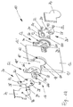
- FIGS. 1A to 2B show a first embodiment of a first embodiment represented such device 10 according to the invention.
- the device 10 comprises at least one connecting device 14, which supports the at least one surface element 12. Especially allows the connection device 14 a connection or fixing the at least one surface element 12 to or on a further surface element 12 and / or additional constructive Components for support.
- the connection device 14 and these additional components for support are hereafter explained in more detail.
- the device 10 has at least one holding device 16, which cooperates with the connecting device 14.
- the holding device 16 In the illustrated embodiment of the device 10 according to FIGS. 1A to 1G is merely a holding device 16 shown. In practice, however, are usually several such holding means 16 for holding the at least one Surface element 12 is provided.
- the connecting device 14 and the holding device 16 of the Device 10 are together via a recess 18 at the respective assigned surface element 12 can be fixed.
- the recess 18, in the embodiment shown in FIGS. 1A to 1G is arranged in a corner region of the surface element 12 includes for this purpose, a clamping portion 18 'to the following recording device 16 to be described in more detail, and a transition section 18 "to one part or the other Part of the holding device 16 and at least a part of Connecting device 14 record.
- the transition section 18 '' extends from the clamping portion 18 'towards a Edge 12 'of the surface element 12, which the / the other Surface element / s 12 faces.
- the at least one holding device 16 is in the recess 18 the surface element 12 positively and / or non-positively fastened.
- the holding device 16 in the recess 18 is such fixed that the at least one holding device 16 with their outer surfaces 20, 20 'in the assembled state or substantially with the planes of the back surface 22 and the front surface 24 of the surface element 12th flees. This is evident in particular from FIG. 1D.
- FIG. 1D On This way is a particularly simple cleaning of the surface element 12 ensured in the assembled state.
- results from such a flush design a extremely beautiful shape of the surface element 12 with the Holding device 16.
- the at least one comprises a holding device 16 two substantially plate-shaped Retaining elements 26, 26 '.
- the plate-shaped holding elements 26, 26 'are of the two opposed to each other facing away surfaces 22, 24 of the surface element 12th forth in the recess 18 of the surface element 12 can be used. in this respect is the holding member 26 in the illustrated in Fig. 1A Embodiment of the back, the holding member 26 'of the Front to the corresponding surfaces 22, 24 of the associated Introduce surface element 12.
- the two holding elements 26, 26 ' which are opposite each other, in shape and dimension adapted to each other.
- the holding elements 26, 26 'are corresponding to FIGS. 1A to 1C each have a holding portion 28, which is substantially the attachment the holding device 16 in the clamping portion 18 'of associated recess 18 is used. Furthermore, the holding elements comprise 26, 26 'corresponding to FIGS. 1A to 1C each one Carrier section 30, which is essentially for receiving and holding the holding device 16 and at least a part of the Connecting device 14 in the transition section 18 '' of the associated Recess 18 is provided. This will be the holding section 28 in the clamping portion 18 'of the corresponding recess 18 recorded. The carrier section 30 is in contrast Receiving in the transition section 18 '' of the associated recess 18th
- the holding portion 28 and the support portion 30 of the two holding elements 26, 26 ' as indicated in FIGS. 1A and 1E, essentially have a thickness d that is slightly smaller as half the thickness D of the surface element 12th
- the two holding elements 26, 26 ' are connected to one another or screwed, via at least one screw 32. Without to be shown in detail, could a screw 32nd approximately in the middle in the holding section 28 of the respective holding element 26, 26 'may be arranged.
- FIG. 1A to 1G four screws 32 are provided, which are the two holding elements 26, 26 'set to each other.
- the four screws 32 are evenly over the holding portion 26 and the support portion 30 of the respective holding element 26, 26 'distributed and arranged mirror-symmetrically to each other.
- FIG. 1A also shows that the one holding element 26 'of the two holding elements 26, 26 'with four holes 34 for receiving the screws 32 provided.
- the other holding element 26 of the two Holding elements 26, 26 ' however, with four threaded holes 36th equipped for locking the screws 32.
- this has a holding element 26 of the two holding elements 26, 26 'a recess or the like recess 38th on, the inclusion of at least a portion of the connecting device 14 serves.
- the other holding element 26 'of the two holding elements 26, 26 ' is connected to the connecting device 14 or a part of it connectable.
- the other holding element 26 ' provided with a bore 40 or the like, which receives a screw 42 (see Fig. 2B and 5A, 5B).
- the Screw 42 is konterbar in a threaded bore 44.
- the threaded hole 44 is located in the at least part of the connecting device 14 for their attachment.
- the longitudinal axis 46 of the elongated hole formed bore 40 extends essentially parallel to an edge 12 'of the surface element 12.
- Such a structural design has the Advantage that when holding the surface element 12 via a Recess 18 in the corner region of the surface element 12 a Compensation of inaccuracies, which, for example, in the Production result, but also by spatial construction conditions are encountered in one direction, namely in the direction of Longitudinal axis 46, is possible.
- Such a construction brings with mutual support of two surface elements 12 in the corner area a further advantage with himself.
- the support element 52 is preferably made of plastic, in particular polyoxymethylene, polyester, ABS, acrylic, polycarbonate, Tetrafluoroethylene or impax, with or without glass-fiber reinforcement, when the surface element 12 is made of glass.
- two are each Support elements 52 between the surface element 12 and the respective Holding element 26, 26 'of the holding device 16 is provided.
- the two support element 52 are identical to one another in this respect and come with their mutually facing backs 54 each in contact. However, without being detailed, it is also conceivable to design the support element 52 in one piece.
- each clamping surfaces 58 the in the embodiment of the device 10 according to FIGS. 1A to 1G cone or cone (dull) are formed.
- the Clamping surfaces 58 of the support elements 52 in turn act accordingly formed clamping surfaces 60 on the inner circumference 62 of the Clamping portion 18 'and the transition portion 18' 'of the respective Recess 18 together.
- clamping surfaces 58 in any way different, for example, hemispherical or dome-shaped and / or rounded off.
- the clamping surfaces 60 would then be shaped accordingly.
- the respective one Support element 52 in its basic form substantially to the Basic shape of a holding element 26 with the recess or adapted to the same recess 38.
- the support element 52 also with a slot 64 or the like recess Mistake.
- the slot 64 divides the support element 52 thereby in two mirror-symmetrically identical halves 66, 66 '.
- a ganwulst or similar edge (increase) 70 is provided, with which the respective associated holding element 26, 26 'over the edges 72 at least partially in contact comes.
- the holding device 16 and the connecting device 14 at least partially by a cover 74 or the same cover can be covered. It is preferred that the outer surfaces of the cover 74 in the mounted state with or substantially with the outer surfaces 22, 24 of the respective surface element 12 are aligned.
- the respective cover element 74 by means of a Snap or the like locking connection on the holding device 16 are attached.
- one or more Latches 76 at the respective holding element 26, 26 'associated Surface of the cover 74 may be provided with the corresponding recesses 78 on the respective holding element 26, 26 'cooperate and can be brought into mutual engagement are.
- a uniform Surface of the surface element 12 together with the invention Device 10 obtained.
- a cleaning of the releasably supported Surface element 12 is thus particularly simple. As well is a buildup of dirt or dust in the area of the device 10 counteracted.
- the holding device 16 and / or the connecting device 14 can depending on the use, application and customer requirements made of metal, such as (non-rusting) Steel, stainless steel, aluminum, brass, zinc, gunmetal alloys or an alloy thereof, to be arbitrary to absorb and support large forces. That's the way it works in the surface element 12 shown schematically in all Usually by a surface element of larger dimensions with inevitable large weight forces, such as in the case of a Glass pane or glass door opening from the device 10 after the Invention is to be kept.
- metal such as (non-rusting) Steel, stainless steel, aluminum, brass, zinc, gunmetal alloys or an alloy thereof
- the holding device 16 and / or the connecting device 14 or at least parts thereof made of plastic, for example Polyoxymethylene, polyester, ABS, acrylic, polycarbonate, tetrafluoroethylene or Impax, with or without glass fiber reinforcement, manufacture.
- plastic for example Polyoxymethylene, polyester, ABS, acrylic, polycarbonate, tetrafluoroethylene or Impax, with or without glass fiber reinforcement, manufacture.
- connection means 14 formed rotationally fixed.
- the connecting device 14 essentially plate, web or the like band-shaped.
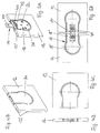
- the structural design of the connection device 14 corresponding to FIGS. 2A and 2B is shown in FIG. 3A again reproduced in detail.
- the connecting device 14 also in of any other form, depending on the needs, Requirements and spatial conditions. So is the connecting device 14 according to the Fig. 3B substantially designed as a square plate.
- the connection device 14 according to FIG. 3C is L-shaped, wherein the two legs have the same length. Likewise, it is conceivable, one of the two legs with a To provide length that is greater than that of the other Leg.
- the connecting device 14 according to FIG. 3D finally has T-shape.
- the connecting means 14 are therefore Although differently shaped, but each plate-shaped designed.
- the connecting devices extend 14 each in a common plane.
- the embodiment of the device 10 according to the invention which in 4A to 5B is substantially the same as that shown in Figs FIGS. 1A to 2B coincide.
- the only difference is the shape of the recess 18 in the surface element 12. Accordingly Are the individual components to the modified Basic shape of the recess 18 adapted.
- the different shape and dimension of the recess 18 results from the fact that the recess is not in a corner region of the surface element 12th formed, but is provided in a straight edge region.
- FIGS. 6A to 6E schematically show various connection possibilities several surface elements 12 to each other.
- FIG. 6A two surface elements 12 are in FIG a straight edge region shown. Suitable for this purpose a connecting device 14 according to FIG. 3A.
- FIG. 6B two surface elements 12 are each in one Corner area shown.
- FIG. 3A two surface elements 12 are shown, which together are connected or held over the corner area.
- a connection device is suitable 14 according to FIG. 3C.
- Fig. 6D are two Surface elements 12 held together over the corner area and additionally with a surface element 12 in the straight edge region connected.
- a T-shaped connecting device 14 accordingly of Fig. 3D is suitable.
- Fig. 6E is a possibility shown, a total of four surface elements 12 in the respective corner area to each other to fix.
- a connection device 14 accordingly of Fig. 3B suitable suitable.
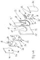
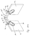
- Such an angled connecting device 14 ' is, for example in the embodiment of the device 10 according to Figs. 7A to 7D realized. Otherwise, the embodiment is correct 7A to 7D with that of FIGS. 1A to 2B match.
- the connecting device 14 ' is in the embodiment according to the Fig. 7D designed such that the two in At an angle of 90 ° arranged surface elements 12 slightly spaced apart from each other. So there is a small gap 80 between the edge 12 'of the one surface element 12 and the front surface 24 of the other surface element 12 available.
- This gap 80 is arbitrarily changeable, i. can be scaled down to zero or arbitrary be enlarged.
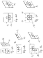
- connection means 14 ' which are substantially angled in each case, shown.
- the connecting device 14 'according to the Fig. 8A corresponds to those already in connection with the embodiment of the device 10 of FIG. 7A to 7D is explained.
- Fig. 8B is a connection means 14 ', which are not at an angle of 90 °, but angled from 130 °.
- FIG. 8D is an angled connecting device 14 ', which at the same time T-shaped is designed.
- Such a connection device 14 ' is suitable for example for separating several side by side lying shower or toilet cubicles.
- FIGS. 8D to 8G Connecting devices 14, 14 ' are substantially identical with those of Figs. 3A and 8A to 8C.
- These connecting devices 14, 14 'each for holding a surface element 12 at one another surface element 12 in the form of, for example, a Wall element or a wall of a bathroom or the like is provided.
- FIGS. 9A to 9D of one or more surface elements 12 further surface elements 12 shown schematically.
- FIGS. 9A, 9B and 9D are in each case connections or holders shown between two surface elements 12 made of glass.
- 9C a surface element 12 made of glass directly on a surface element 12 in the form of a wall of a Room screwed.
- FIGS. 10A to 10D another embodiment of the Device 10 according to the invention. This is different from that of FIGS. 7A to 7D only in that the connecting device 14 '' with a hinge 84 provided or configured as a rotary joint 84.
- a surface element 12 the is immovable, with a surface element 12, opposite the fixed surface element 12 is relatively rotatable, such as to connect a door to a shower or toilet cabin.
- FIGs. 11A to 11D are still other embodiments shown by connecting means 14 '' '.
- a fastener 86 for (additional) support of at least a surface element 12 on another surface element 12th or the like attached.
- the fastener 86 is thereby facing away from the at least one surface element 12 and advantageously in the plane of the at least one surface element 12 arranged.
- the fastener 86 in the embodiment of Fig. 11A designed as a pin or pin 88.
- the bolt or pin 88 can in a corresponding hole or Sleeve, for example, in a ceiling or on the floor, intervene. Consequently, both surface elements 12 are relatively rotatable not only to each other, but in addition to the room designed.
- the pin or pin 88 ensures an additional anchoring and thus for an increase of Stability.
- the fastener 86 is another Section 90, which includes an eye 92 over which the two surface elements 12 at a continuous Rod 94 can be fixed.
- FIG. 11C shows a fastening element 86, in which the connecting device 14 '' 'with a hinge 84 is equipped and an extended portion 96th to, for example, the surface element 12 via two Holes 98 on the further surface element 12 in the form of a To turn wall.
- the fastener 86 is on the connector 14 '' 'with an extended portion 100 provided, which is angled end to the two to each other relatively rotatable surface elements 12, for example the ceiling or floor (not shown), i. depend or réellemenrn.
- FIGS. 1A to 11D have the two holding elements 26, 26 'of at least a holding device 16 and the connecting device 14 is substantially a thickness d, which added together slightly is smaller than the thickness D of the surface element 12th is.
- the thickness of the connecting device 14 should accordingly selected the male holding forces and on the thicknesses of the holding elements 26, 26 'as well as the support elements 52 adapted to the thickness D of the surface element 12 possible not to exceed. In this way it is ensured that the at least one holding device 16 with the outer surfaces 20, 20 'in the assembled state in Substantially with the planes of the surfaces 22, 24 of at least a surface element 12 coincide.
- FIGS. 12A to 12D are still different Embodiments of recesses 18 shown.
- the clamping portion 18 'of the recess 18 in the embodiment 12A through a bore 102 in the surface element 12 formed, wherein the circumferential angle ⁇ greater than 180 ° is.
- the transition portion 18 '' of the recess 18 is formed by a further bore 104.
- the clear distance e the transition section 18 '' of the recess 18 can thereby be equal to or greater than the diameter of the clamping portion 18 'of the recesses 18, i. as the diameter of the hole 102nd
- transition portion 18 "of the recesses 18 also according to the embodiment of FIG. 12B (Aus) be cut.
- FIG. 12C is the transition section 18 "of FIG Recesses 18 while tangential (off) cut or how From Fig. 12D shows tangential (off) cut and additionally broken in edge regions 108.
- the two opposing holding elements 26, 26 'and / or the cover 74 each with an outer surface 20, 20 'is formed corresponding to the so-called lotus blossom effect liquid and / or stain resistant.
Abstract
Description
Die Erfindung betrifft eine Anordnung mit einer Vorrichtung zur lösbaren Halterung von wenigstens einem Flächenelement und deren Verwendung.The invention relates to an arrangement with a device for releasable mounting of at least one surface element and its Use.
Derartige Vorrichtungen sind allgemein bekannt. Allerdings haben sich derartige Vorrichtungen in der Praxis als ausgesprochen nachteilig erwiesen. So dienen solche Vorrichtungen unter anderem als Halter oder dergleichen, beispielsweise als Beschläge von Scheiben aus Glas oder Kunststoff für Duschkabinen etc., die zumeist beidseits aus der Ebene der Oberflächen der Glasscheibe hervorstehen. Die Vorrichtungen stellen mithin einen unerwünschten Staub- und Schmutz- bzw. Feuchtigkeitsfänger dar. Auch ist eine Reinigung einer Glasscheibe im Bereich dieser Vorrichtungen nicht möglich, zumindest wesentlich erschwert. Die Glasscheibe jedenfalls kann nicht durchgehend mit einer Gummilippe zur Entfernung von Reinigungsflüssigkeit abgezogen werden. Vielmehr ist dann um diese Vorrichtungen mit der Gummilippe herum zu fahren, unter Umständen sogar mit der Folge, dass eigentlich zu entfernende Reinigungsflüssigkeit in die Vorrichtungen selbst eindringt. Auch handelt es sich dabei sämtlich um Vorrichtungen, die entweder nicht ausreichend stabil oder eine sehr aufwendige Bauweise und große Bauhöhe aufweisen. Zudem besitzen diese Vorrichtungen den Nachteil, dass deren Größenverhältnisse und Abmessungen vorbestimmt und somit nicht veränderbar sind. Eine individuelle Anpassung an Flächenelemente mit Toleranzungenauigkeiten ist bei diesen Vorrichtungen daher nicht möglich.Such devices are well known. However, have Such devices are pronounced in practice as proved disadvantageous. Thus, such devices serve among others as a holder or the like, for example as fittings of glass or plastic panes for shower cubicles etc., which mostly on both sides of the plane of the surfaces of the glass protrude. The devices thus represent an undesirable Dust and dirt or moisture trap. Also is a cleaning of a glass sheet in the range of these devices not possible, at least considerably more difficult. The glass pane Anyway, can not be consistent with a rubber lip for removal be removed from cleaning fluid. Rather, it is then to drive around these devices with the rubber lip, possibly even with the consequence that actually be removed Cleaning liquid penetrates into the devices themselves. Also, these are all devices, either not sufficiently stable or a very expensive Construction and large height have. In addition, these devices have the disadvantage that their proportions and dimensions are predetermined and thus not changeable. An individual Adaptation to surface elements with tolerance inaccuracies is therefore not possible with these devices.
Der Erfindung liegt daher die Aufgabe zugrunde, eine Vorrichtung zur lösbaren Halterung von wenigstens einem Flächenelement zur Verfügung zu stellen, mit welcher sich die obigen Nachteile verhindern lassen, welche mithin eine besonders einfache Reinigung sämtlicher Oberflächen des wenigstens einen von der Vorrichtung gehaltenen Flächenelementes ermöglicht und zugleich konstruktiv besonders einfach, kompakt und stabil, damit einhergehend kostengünstig herstellbar ist, ohne weiteres individuell Fertigungsungenauigkeiten der miteinander zu verbindenden Flächenelemente ausgleicht und ausgesprochen leicht montier- und demontierbar ist, sowie eine vorteilhafte Verwendung dieser Vorrichtung bereitzustellen.The invention is therefore based on the object, a device for releasably supporting at least one surface element to To provide, with which prevent the above disadvantages which, therefore, a particularly simple cleaning all surfaces of the at least one of the device held surface element allows and at the same time constructive particularly simple, compact and stable, and consequently cost-effective can be produced, without further individual manufacturing inaccuracies the surface elements to be joined together compensates and is extremely easy to assemble and disassemble is, as well as an advantageous use of this device provide.
Diese Aufgabe wird in vorrichtungstechnischer Hinsicht durch die Merkmale des Anspruchs 1 gelöst.This object is in device-technical terms by the Characteristics of claim 1 solved.
Demnach lassen sich gleichmäßige und durchgehende Oberflächen des/der von der Vorrichtung gehaltenen Flächenelemente/s erreichen, die besonders einfach gereinigt und sauber gehalten werden können. Zudem ergibt sich ein formschönes Aussehen der erfindungsgemäßen Vorrichtung insgesamt. Des Weiteren ist eine kompakte und stabile Bauweise der gesamten Vorrichtung erreicht. Weiterhin hat die erfindungsgemäße Vorrichtung den wesentlichen Vorteil, ohne weiteres Maßungenauigkeiten und Fertigungstoleranzen auszugleichen, indem deren Form und Abmessung entsprechend den gegebenen Räumlichkeiten individuell veränderbar sind. Nicht zuletzt hieraus resultierend ergibt sich eine ausgesprochen leichte Handhabung bei der Montage bzw. Demontage. Schließlich ist auch eine kostengünstige Herstellungs- und Lagerweise der Vorrichtung nach der Erfindung ermöglicht.Accordingly, uniform and continuous surfaces can be achieved reach the surface element (s) held by the device, which are particularly easy to clean and keep clean can. In addition, a shapely appearance of the invention Overall device. Furthermore, it is a compact one and stable construction of the entire device achieved. Furthermore, the device according to the invention has the essential Advantage, without further dimensional inaccuracies and manufacturing tolerances compensate by their shape and dimensions accordingly The given premises are individually changeable. Not the last result is a pronounced one easy handling during assembly or disassembly. After all is also a cost-effective production and storage of the Device according to the invention allows.
Von ganz besonders großer Bedeutung für eine Flächenbündigkeit zwischen der Halteeinrichtung mit deren außen liegenden Flächen im montierten Zustand und dem wenigstens einen Flächenelement mit dessen Oberflächen, die im Wesentlichen, d.h. weitgehend oder genau, in eine Ebene fallen sollen, ist das Merkmal, dass die Ausnehmung des wenigstens einen Flächenelementes einen Klemmabschnitt und einen sich von dem Klemmabschnitt hin zu einer Kante des wenigstens einen Flächenelementes erstreckenden Übergangsabschnitt zur Aufnahme der Halteeinrichtung und gegebenenfalls wenigstens eines Teiles der Verbindungseinrichtung umfasst. So kann es entsprechend der Ausgestaltung der Verbindungseinrichtung förderlich sein, neben der Halteeinrichtung wenigstens auch einen Teil der Verbindungseinrichtung in der Ausnehmung aufzunehmen bzw. in dieser versenkt anzuordnen, um eine gleichmäßige und durchgehende Oberfläche des/der von der Vorrichtung gehaltenen Flächenelemente/s zu erhalten.Of particular importance for a flush surface between the holding device with its outer surfaces in the assembled state and the at least one surface element with its surfaces substantially, i. largely or exactly, to fall into a plane is the feature that the recess of the at least one surface element a Clamping portion and a from the clamping portion to a Edge of at least one surface element extending Transition section for receiving the holding device and optionally at least part of the connecting device comprises. So it may according to the configuration of the connecting device be beneficial, in addition to the holding device at least also a part of the connecting device in the recess to record or sunk in this order to a uniform and continuous surface of the / of the device maintained surface elements / s.
Erfindungsgemäß umfasst die mindestens eine Halteeinrichtung zwei im Wesentlichen plattenförmige Halteelemente, die von zwei einander gegenüberliegenden Oberflächen des wenigstens einen Flächenelementes her in die Ausnehmung des Flächenelementes einsetzbar und in der Ausnehmung einander gegenüberliegend befestigbar sind. Auf diese Weise ist eine zuverlässige Halterung des zugeordneten Flächenelementes, das in aller Regel ein Vielfaches des Gewichts von demjenigen der Halteeinrichtung aufweist, ermöglicht. Auch ist hierdurch eine einfache, schnelle und zuverlässige Montage der Halteeinrichtung in dem zugeordneten Flächenelement bzw. anschließende Demontage dessen zu Wartungs- oder Reparaturzwecken ermöglicht.According to the invention, the at least one holding device comprises two substantially plate-shaped holding elements, of two opposite surfaces of at least a surface element ago in the recess of the surface element can be used and in the recess opposite each other are fastened. This way is a reliable one Holder of the associated surface element, as a rule a multiple of the weight of that of the holding device has enabled. Also, this is a simple, fast and reliable mounting of the holding device in the associated Surface element or subsequent dismantling thereof to maintenance or repair purposes.
Weitere vorteilhafte Einzelheiten der erfindungsgemäßen Vorrichtung sind in den Ansprüchen 2 bis 26 beschrieben.Further advantageous details of the device according to the invention are described in claims 2 to 26.
Durch die erfindungsgemäße Ausgestaltung von den zwei einander gegenüberliegenden Halteelementen, die in Form und Abmessung aneinander angepasst sind, ist einerseits sichergestellt, dass die Halteelemente in der Ausnehmung des Flächenelementes aufgenommen werden können, ohne mit deren außen liegenden Flächen im montierten Zustand über die Ebenen der Oberflächen des wenigstens einen der zwei Flächenelemente hervorzustehen. Andererseits ist es möglich, die Halteelemente derart auszubilden, dass eine gegenseitige Halterung bzw. Abstützung in der Ausnehmung des zugeordneten Flächenelementes erfolgen kann. Hierdurch kann die Belastungsfähigkeit, Steifigkeit und Festigkeit der Halteeinrichtung insgesamt erhöht werden.Due to the inventive design of the two each other opposite holding elements in shape and dimension to each other are on the one hand ensured that the Retained holding elements in the recess of the surface element can be installed without having their outside surfaces in the assembled State over the planes of the surfaces of at least to stand out one of the two surface elements. On the other hand it is possible to form the holding elements such that a mutual Holder or support in the recess of the associated Surface element can be done. As a result, the load capacity, Stiffness and strength of the holding device be increased overall.
Das Halteelement ist in vorteilhafter Weise mit einem Halteabschnitt und einem Trägerabschnitt versehen. Der Halteabschnitt dient dabei im Wesentlichen einer Befestigung der Halteeinrichtung in der Ausnehmung. Der Trägerabschnitt ist hingegen im Wesentlichen zur Aufnahme und Halterung der Halteeinrichtung und gegebenenfalls wenigstens eines Teiles der Verbindungseinrichtung in der Ausnehmung vorgesehen.The holding element is advantageously with a holding portion and a support portion. The holding section essentially serves to secure the holding device in the recess. By contrast, the carrier section is essentially for receiving and holding the holding device and optionally at least part of the connecting device provided in the recess.
So liegt es im Rahmen der Erfindung, zwei Halteelemente der Halteeinrichtung nach Anspruch 2 miteinander lösbar zu verbinden. Als besonders vorteilhaft eignet sich in diesem Zusammenhang eine Schraubverbindung, da die Klemmkraft bzw. Vorspannkraft von Schrauben zum Beispiel bei Vorhandensein von Maßungenauigkeiten etc. individuell einstellbar ist.So it is within the scope of the invention, two holding elements of Retaining device according to claim 2 releasably connect to each other. Particularly advantageous in this context a screw because the clamping force or biasing force of screws, for example, in the presence of dimensional inaccuracies etc. is individually adjustable.
Die zwei Halteelemente sind in vorteilhafter Weise nach den Ansprüchen 3 und 4 ausgebildet.The two retaining elements are advantageously according to the claims 3 and 4 formed.
Die konstruktiven Maßnahmen des Anspruchs 5 gewährleisten einen Toleranzausgleich, der durch Fertigungsungenauigkeiten und/oder Maßabweichungen, welche durch Baumaßnahmen von Räumlichkeiten, in welchen Flächenelemente miteinander verbunden werden sollen, auftreten können.The constructive measures of claim 5 ensure a Tolerance compensation caused by manufacturing inaccuracies and / or Dimensional deviations resulting from building measures of premises, in which surface elements are to be connected to each other, may occur.
Als besonders vorteilhaft für den Fall, dass die zwei Halteelemente jeweils aus Metall bestehen, gleichzeitig aber das Flächenelement aus Glas ausgestaltet ist, haben sich die Maßnahmen des Anspruchs 6 betreffend ein Auflageelement oder dergleichen Beilageelement herausgestellt. Einerseits lässt sich auf diese Weise sicherstellen, dass die erfindungsgemäße Vorrichtung an dem jeweiligen Flächenelement sicher befestigbar und damit nicht selbsttätig lösbar ist. Andererseits ist dadurch verhindert, dass bei Demontage zu große Klemmkräfte von der Halteeinrichtung der erfindungsgemäßen Vorrichtung auf das Flächenelement ausgeübt und damit unter Umständen schädliche Spannungsverhältnisse in dem Flächenelement erzeugt werden. Die Montage ist somit zugleich vereinfacht.As particularly advantageous in the event that the two retaining elements each made of metal, but at the same time the surface element Made of glass, the measures have become of claim 6 concerning a support element or the like Side element exposed. On the one hand, this can be on Make sure that the device according to the invention the respective surface element securely fastened and thus can not be solved automatically. On the other hand, this prevents that during disassembly too large clamping forces from the holding device the device according to the invention on the surface element exercised and thus possibly harmful Voltage ratios are generated in the surface element. The assembly is thus simplified at the same time.
Für eine vereinfachte Handhabung bei der Montage und vielseitige sowie individuelle Ausrichtung des wenigstens einen Flächenelementes liegt es weiterhin besonders im Rahmen der Erfindung, das Auflageelement nach Anspruch 7 auszugestalten. Dadurch ist zugleich sichergestellt, dass die Halteeinrichtung der erfindungsgemäßen Vorrichtung nach erfolgtem Formschluss durch Einsetzen in die entsprechende Ausnehmung zusätzlich durch einen Kraftschluss in der Ausnehmung gesichert werden kann. Es können somit hohe Kräfte und Momente, die insbesondere durch das Gewicht gro-βer Glasplatten erzeugt werden, ohne weiteres sicher und zuverlässig aufgenommen und/oder übertragen werden.For simplified handling during assembly and versatile and individual orientation of the at least one surface element it is still particularly within the scope of the invention, the Design support element according to claim 7. This is at the same time ensures that the holding device of the invention Device after completion of form fit by inserting in the corresponding recess additionally by a frictional connection can be secured in the recess. It can thus high forces and moments, in particular by the weight gro-βer Glass plates are produced, easily safe and reliable be recorded and / or transmitted.
Durch die Maßnahmen der Ansprüche 8 und 9 ist es in diesem Zusammenhang
möglich, Toleranzungenauigkeiten oder auch Montageungenauigkeiten
infolge von vor Ort anzutreffenden Raum-
bzw. Platzverhältnissen, die zugleich auf die Verbindung zwischen
Halteeinrichtung und Flächenelement Einfluss nehmen, auf
einfache Weise auszugleichen. Mögliche durch Maßungenauigkeiten
hervorgerufene Spannungen sind dabei vermieden bzw. ohne
weiteres ausgleichbar. Zugleich ist sichergestellt, dass die
Halteelemente, die in aller Regel aus Metall bestehen, nicht
mit dem Flächenelement selbst in Berührung kommen und das Flächenelement
gegebenenfalls beschädigen, insbesondere wenn dieses
aus Glas besteht.By the measures of
Des Weiteren liegt es im Rahmen der Erfindung, die Verbindungseinrichtung nach Anspruch 10 drehfest auszubilden.Furthermore, it is within the scope of the invention, the connecting device form according to claim 10 rotatably.
In diesem Zusammenhang ist die erfindungsgemäße Ausbildung der Verbindungseinrichtung nach Anspruch 11 besonders vorteilhaft.In this context, the inventive design of the Connecting device according to claim 11 particularly advantageous.
In alternativer Ausgestaltung dazu kann die Verbindungseinrichtung
nach Anspruch 12 auch abgewinkelt sein. So kann der
Winkel zum Beispiel 90° oder 135° betragen. In an alternative embodiment, the connecting device
be angled according to
Des weiteren liegt es im Rahmen der Erfindung, die Verbindungseinrichtung nach Anspruch 13 drehbar auszugestalten. Die Verbindungseinrichtung der erfindungsgemäßen Vorrichtung ist insoweit mit einem Drehgelenk versehen bzw. als Scharnier oder Drehgelenk ausgebildet, derart, dass das wenigstens eine Flächenelement gegenüber einem anderen Flächenelement, das zweckmäßigerweise starr bzw. feststehend ist, relativ verdreht bzw. verschwenkt werden kann.Furthermore, it is within the scope of the invention, the connecting device To design according to claim 13 rotatable. The connection device the device according to the invention is so far provided with a hinge or as a hinge or swivel joint formed such that the at least one surface element opposite another surface element, which expediently is rigid or fixed, relatively twisted or pivoted can be.
Entsprechend den Merkmalen des Anspruchs 14 ist die Verbindungseinrichtung
vorteilhaft ausgestaltet, wobei das Befestigungselement
als kumultative oder alternative Maßnahme, um das
wenigstens eine Flächenelement abzustützen dient.According to the features of
Das Merkmal nach Anspruch 15 ermöglicht eine ausgesprochen vielseitige, zudem individuelle und flexible Anpassung an räumliche Gegebenheiten und architektonische Gestaltungen.The feature of claim 15 allows pronounced versatile, also individual and flexible adaptation to spatial Conditions and architectural designs.
Zweckmäßigerweise ist/sind die Halteeinrichtung und/oder die
Verbindungseinrichtung nach Anspruch 16 ausgebildet.Appropriately, is / are the holding device and / or the
Connecting device formed according to
Die Merkmale des Anspruchs 17 gewährleisten in vorteilhafter Weise, dass die zwei Halteelemente der Halteeinrichtung und/oder die Verbindungseinrichtung zusammen mit dem/den Auflageelement/en nicht über die Oberflächen des Flächenelementes hinausstehen.The features of claim 17 ensure in an advantageous Way, that the two holding elements of the holding device and / or the connection device together with the support element (s) do not protrude beyond the surface of the surface element.
Durch die Maßnahmen des Anspruchs 18 ergibt sich eine gleichmäßige
und durchgehende Oberfläche der erfindungsgemäßen Vorrichtung
mit dem Vorteil einer vereinfachten Reinigung und Sauberhaltung,
und zwar insbesondere auch wenn die Flächenelemente aus
Glas bestehen und insoweit einer verhältnismäßig intensiven
Reinhaltung bedürfen. Zudem ergibt sich ein formschönes Aussehen
der erfindungsgemäßen Vorrichtung insgesamt. Daher können die
außen liegenden Flächen des Halteelementes, beispielsweise ein
Schraubenschlitz, Innensechskantprofil oder dergleichen, überdeckt
werden.The measures of
Von großem Interesse für eine vereinfachte Reinigung und Sauberhaltung der erfindungsgemäßen Vorrichtung sind weiterhin die Merkmale des Anspruchs 19. Die außen liegende Oberfläche der zwei einander gegenüberliegenden Halteelemente kann dabei entweder durch die chemische Materialzusammensetzung der Halteelemente, welche zum Beispiel hydrophob ausgestaltet ist, erreicht werden. Ebenso ist es denkbar, eine flüssigkeits- und/oder schmutzabweisende Oberfläche der Halteelemente und/oder der gesamten Vorrichtung insgesamt dadurch zu erreichen, dass mechanische Oberflächenmuster bzw. -profile im Nanobereich vorgesehen sind, welche einer Haftung von Flüssigkeit und/oder Schmutz etc. entgegenwirken. Bei letzterer Ausgestaltung findet beispielsweise der sogenannte Lotusblüteneffekt Verwendung.Of great interest for a simplified cleaning and keeping clean the device according to the invention are still the Features of claim 19. The outer surface of the two opposing holding elements can either by the chemical material composition of the holding elements, which is designed, for example, hydrophobic achieved become. It is also conceivable, a liquid and / or dirt-repellent surface of the holding elements and / or the entire Overall device to achieve that mechanical Surface patterns or profiles provided in the nano range which are a liability of liquid and / or dirt, etc. counteract. In the latter embodiment, for example the so-called lotus flower effect use.
Zweckmäßigerweise sind der Klemmabschnitt und der Übergangsabschnitt
der Ausnehmung durch die Maßnahmen der Ansprüche 20 bis
26 ausgebildet.Conveniently, the clamping portion and the transition section
the recess by the measures of
Schließlich liegt es noch im Rahmen der Erfindung entsprechend
den Ansprüchen 27 und 28, eine Vorrichtung gemäß der Erfindung
zur lösbaren Halterung von wenigstens einem Flächenelement aus
Metall, Kunststoff, Holz, Glas oder einer Kombination daraus zu
verwenden bzw. als Beschlag oder dergleichen zur Montage von
Raumteilern, Trennwänden oder sonstigen Trennelementen, Glasvitrinen,
Glaslandschaften in Büroräumen, Glas- und Kunststoffscheiben
sowie Glas- und Kunststofftüren, insbesondere von bzw.
für Dusch- oder Toilettenkabinen oder dergleichen Nasszellen,
und/oder zur Befestigung von Bauteilen, wie Halterungen, Handgriffe
oder dergleichen Armaturen, und dergleichen Gegenstände
zu benutzen. Die Verwendung der erfindungsgemäßen Vorrichtung
insbesondere als Beschlag führt zu dem ausgesprochen großen Vorteil,
dass Glasvitrinen leicht montierbar und ebenso demontierbar
sind, damit jederzeit transportierbar sind, deren Reinigung
und Sauberhaltung ausgesprochen einfach ist, deren Transparenz
weitgehend erhalten bleibt und schließlich Maßungenauigkeiten
und Fertigungstoleranzen ohne weiteres auszugleichen imstande
ist.Finally, it is still within the scope of the invention accordingly
to
Weitere Merkmale, Vorteile und Einzelheiten der Erfindung ergeben sich aus der nachfolgenden Beschreibung einiger bevorzugter Ausführungsformen der Erfindung sowie anhand der Zeichnungen. Hierbei zeigen:
- Fig. 1A
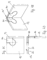
- eine auseinandergezogene perspektivische Ansicht einer ersten Ausführungsform einer erfindungsgemäß ausgebildeten Vorrichtung zur lösbaren Halterung von wenigstens einem Flächenelement,
- Fig. 1B bis 1D
- eine perspektivische Ansicht, eine Draufsicht und eine Seitenansicht der Ausführungsform der erfindungsgemäß ausgebildeten Vorrichtung nach der Fig. 1A im montierten Zustand,
- Fig. 1E bis 1G
- eine Draufsicht, eine Seitenansicht und eine Querschnittsansicht durch die Ausführungsform der erfindungsgemäßen Vorrichtung nach der Fig. 1A längs der Linie IG-IG in der Fig. 1E im montierten Zustand zusammen mit einem Abdeckelement,
- Fig. 2A
- eine perspektivische Ansicht der Ausführungsform der erfindungsgemäß ausgebildeten Vorrichtung nach der Fig. 1A im montierten Zustand zusammen mit einer erfindungsgemäßen Verbindungseinrichtung,
- Fig. 2B
- eine Draufsicht auf die Ausführungsform der erfindungsgemäß ausgebildeten Vorrichtung nach der Fig. 1A im montierten Zustand zur Verbindung von zwei zueinander benachbarten Flächenelementen in einer gemeinsamen Ebene,
- Fig. 3A bis 3D
- Draufsichten und perspektivische Ansichten verschiedener Ausführungsformen von erfindungsgemäß ausgebildeten Verbindungseinrichtungen,
- Fig. 4A
- eine auseinandergezogene perspektivische Ansicht einer weiteren Ausführungsform einer erfindungsgemäß ausgebildeten Vorrichtung zur lösbaren Halterung von wenigstens einem Flächenelement,
- Fig. 4B bis 4D
- eine perspektivische Ansicht, eine Draufsicht und eine Seitenansicht der Ausführungsform der erfindungsgemäß ausgebildeten Vorrichtung nach der Fig. 4A im montierten Zustand zusammen mit einem Abdeckelement,
- Fig. 5A
- eine perspektivische Ansicht der Ausführungsform der erfindungsgemäß ausgebildeten Vorrichtung nach der Fig. 4A im montierten Zustand zusammen mit einer erfindungsgemäßen Verbindungseinrichtung,
- Fig. 5B
- eine Draufsicht auf die Ausführungsform der erfindungsgemäß ausgebildeten Vorrichtung nach der Fig. 4A im montierten Zustand zur Verbindung von zwei zueinander benachbarten Flächenelementen in einer gemeinsamen Ebene,
- Fig. 6A bis 6E
- schematische Draufsichten und perspektivische Ansichten von verschiedenen Ausführungsbeispielen erfindungsgemäßer Vorrichtungen zur lösbaren Halterung von zwei, drei und vier Flächenelementen in einer gemeinsamen Ebene,
- Fig. 7A
- eine perspektivische Ansicht einer anderen Ausführungsform einer erfindungsgemäß ausgebildeten Vorrichtung zur lösbaren Halterung von zwei Flächenelementen in zwei unterschiedlichen Ebenen im teilweise montierten Zustand zusammen mit einer Verbindungseinrichtung,
- Fig. 7B bis 7D
- eine perspektivische Ansicht, eine Draufsicht und eine Seitenansicht der Ausführungsform der erfindungsgemäß ausgebildeten Vorrichtung nach der Fig. 7A im montierten Zustand zusammen mit einem Abdeckelement,
- Fig. 8A bis 8H
- Draufsichten und perspektivische Ansichten verschiedener Ausführungsformen von weiteren erfindungsgemäß ausgebildeten Verbindungseinrichtungen,
- Fig. 9A bis 9D
- schematische Draufsichten und perspektivische Ansichten von verschiedenen Ausführungsbeispielen erfindungsgemäßer Vorrichtungen zur lösbaren Halterung von zwei, drei und vier Flächenelementen in verschiedenen Ebenen,
- Fig. 10A
- eine perspektivische Ansicht einer noch anderen Ausführungsform einer erfindungsgemäß ausgebildeten Vorrichtung zur lösbaren Halterung von zwei Flächenelementen im teilweise montierten Zustand zusammen mit einer Verbindungseinrichtung,
- Fig. 10B bis 10D
- eine perspektivische Ansicht, eine Draufsicht und eine Seitenansicht der Ausführungsform der erfindungsgemäß ausgebildeten Vorrichtung nach der Fig. 10A im montierten Zustand zusammen mit einem Abdeckelement,
- Fig. 11A bis 11D
- perspektivische Ansichten weiterer Ausführungsformen von erfindungsgemäß ausgebildeten Verbindungseinrichtungen, einmal im unmontierten und einmal im montierten Zustand zur lösbaren Halterung von wenigstens zwei Flächenelementen miteinander, und
- Fig. 12A bis 12D
- verschiedene Ausführungsformen von erfindungsgemäß ausgebildeten Klemm- und Übergangsabschnitten von Ausnehmungen an dem durch die erfindungsgemäße Vorrichtung lösbar zu halternden Flächenelement.
- Fig. 1A
- an exploded perspective view of a first embodiment of an inventive device for releasably supporting at least one surface element,
- Fig. 1B to 1D
- a perspective view, a plan view and a side view of the embodiment of the inventive device according to FIG. 1A in the mounted state,
- Fig. 1E to 1G
- a plan view, a side view and a cross-sectional view through the embodiment of the device according to the invention according to FIG. 1A along the line IG-IG in the Fig. 1E in the assembled state together with a cover,
- Fig. 2A
- a perspective view of the embodiment of the inventive device according to FIG. 1A in the mounted state together with a connecting device according to the invention,
- Fig. 2B
- a plan view of the embodiment of the inventive device according to FIG. 1A in the assembled state for connecting two mutually adjacent surface elements in a common plane,
- Fig. 3A to 3D
- Top views and perspective views of various embodiments of connecting devices according to the invention,
- Fig. 4A
- an exploded perspective view of another embodiment of an inventive device for releasably supporting at least one surface element,
- Fig. 4B to 4D
- a perspective view, a plan view and a side view of the embodiment of the inventive device according to FIG. 4A in the assembled state together with a cover,
- Fig. 5A
- a perspective view of the embodiment of the inventive device according to FIG. 4A in the mounted state together with a connecting device according to the invention,
- Fig. 5B
- a plan view of the embodiment of the inventive device according to FIG. 4A in the assembled state for connecting two adjacent surface elements in a common plane,
- FIGS. 6A to 6E
- schematic plan views and perspective views of various embodiments of inventive devices for releasably supporting two, three and four surface elements in a common plane,
- Fig. 7A
- a perspective view of another embodiment of an inventive device for releasably supporting two surface elements in two different levels in the partially assembled state together with a connecting device,
- Figs. 7B to 7D
- a perspective view, a plan view and a side view of the embodiment of the inventive device according to FIG. 7A in the mounted state together with a cover,
- 8A to 8H
- Top views and perspective views of various embodiments of further inventively designed connecting devices,
- Figs. 9A to 9D
- schematic plan views and perspective views of various embodiments of inventive devices for releasably supporting two, three and four surface elements in different levels,
- Fig. 10A
- a perspective view of yet another embodiment of an inventive device for releasably supporting two surface elements in the partially assembled state together with a connecting device,
- 10B to 10D
- a perspective view, a plan view and a side view of the embodiment of the inventive device according to FIG. 10A in the assembled state together with a cover,
- Figs. 11A to 11D
- Perspective views of other embodiments of inventively designed connecting devices, once in the unassembled and once in the assembled state for releasably supporting at least two surface elements together, and
- FIGS. 12A to 12D
- various embodiments of inventively designed clamping and transition sections of recesses on the releasable to be held by the device according to the invention surface element.
Die erfindungsgemäße Vorrichtung 10 ist zur lösbaren Halterung
von wenigstens einem Flächenelement 12 vorgesehen. Bei der nachfolgenden
Beschreibung von verschiedenen Ausführungsbeispielen
der erfindungsgemäßen Vorrichtung sind einander entsprechende,
gleiche Bauteile jeweils mit identischen Bezugsziffern versehen.The
Die Vorrichtung 10 nach der Erfindung eignet sich zur lösbaren
Halterung von wenigstens einem Flächenelement 12 aus Metall,
Kunststoff, Holz, Glas und Verbundstoffen daraus. Bei dem Flächenelement
12 kann es sich beispielsweise um eine schalldämpfende
Wandpaneele aus Holz, Glasscheibe, Kunststoffscheibe etc.
und/oder eine Wand eines Raumes, zum Beispiel eine Badezimmerwand,
handeln. Auf ausgesprochen vorteilhafte Weise dient die
Vorrichtung 10 nach der Erfindung als Beschlag oder dergleichen
zur Montage von Raumteilern, Glasvitrinen, Glaslandschaften in
Büroräumen, Glas- und Kunststoffscheiben sowie Glas- und Kunststofftüren,
insbesondere von bzw. für Dusch- und Toilettenkabinen
oder dergleichen Nasszellen, und/oder zur Befestigung von
Bauteilen, wie Halterungen, Handgriffe oder dergleichen, Armaturen
und dergleichen Gegenständen. In ganz vorteilhafter Weise
eignet sich die erfindungsgemäße Vorrichtung 10 auch zur lösbaren
Halterung von Trennwänden zwischen jeweils zwei einander benachbarten
sanitären Einrichtungen, wie beispielsweise Waschbekken,
Urinalbecken, Toiletten, Duschen etc.The
Das Flächenelement 12 der Ausführungsform der Vorrichtung 10,
die in den Fig. 1A bis 1G gezeigt ist, ist beispielsweise als
Glasscheibe einer Dusch- oder Toilettenkabine ausgebildet. Das
Flächenelement 12 ist jedoch zur Vereinfachung bei sämtlichen
Ausführungsformen lediglich schematisch dargestellt.The
In den Fig. 1A bis 2B ist nun eine erste Ausführungsform einer
solchen Vorrichtung 10 nach der Erfindung dargestellt. Die Vorrichtung
10 umfasst mindestens eine Verbindungseinrichtung 14,
welche das wenigstens eine Flächenelement 12 haltert. Insbesondere
ermöglicht die Verbindungseinrichtung 14 eine Verbindung
oder Festlegung des wenigstens einen Flächenelementes 12 zu bzw.
an einem weiteren Flächenelement 12 und/oder zusätzlichen konstruktiven
Bauteilen zur Abstützung. Die Verbindungseinrichtung
14 und diese zusätzlichen Bauteile zur Abstützung werden nachfolgend
noch näher erläutert.FIGS. 1A to 2B show a first embodiment of a first embodiment
represented
Darüber hinaus weist die Vorrichtung 10 mindestens eine Halteeinrichtung
16 auf, die mit der Verbindungseinrichtung 14 zusammenwirkt.
Bei der dargestellten Ausführungsform der Vorrichtung
10 nach den Fig. 1A bis 1G ist lediglich eine Halteeinrichtung
16 gezeigt. In der Praxis sind jedoch in aller Regel mehrere
solcher Halteeinrichtungen 16 zur Halterung des wenigstens einen
Flächenelementes 12 vorgesehen.In addition, the
Die Verbindungseinrichtung 14 und die Halteeinrichtung 16 der
Vorrichtung 10 sind gemeinsam über eine Ausnehmung 18 an dem jeweils
zugeordneten Flächenelement 12 fixierbar. Die Ausnehmung
18, die bei der in den Fig. 1A bis 1G gezeigten Ausführungsform
in einem Eckbereich des Flächenelementes 12 angeordnet ist, umfasst
zu diesem Zweck einen Klemmabschnitt 18', um die nachfolgend
noch näher beschriebene Halteeinrichtung 16 aufzunehmen,
und einen Übergangsabschnitt 18'', um einen Teil bzw. den übrigen
Teil der Halteeinrichtung 16 und wenigstens einen Teil der
Verbindungseinrichtung 14 aufzunehmen. Der Übergangsabschnitt
18'' erstreckt sich dabei von dem Klemmabschnitt 18' hin zu einer
Kante 12' des Flächenelementes 12, welche dem/den weiteren
Flächenelement/en 12 zugewandt ist.The connecting
Die mindestens eine Halteeinrichtung 16 ist in der Ausnehmung 18
des Flächenelementes 12 form- und/oder kraftschlüssig befestigbar.
Dabei ist die Halteeinrichtung 16 in der Ausnehmung 18 derart
fixiert, dass die mindestens eine Halteeinrichtung 16 mit
deren außen liegenden Flächen 20, 20' im montierten Zustand zu
bzw. im Wesentlichen mit den Ebenen der rückseitigen Oberfläche
22 und der vorderseitigen Oberfläche 24 des Flächenelementes 12
fluchtet. Dies ergibt sich insbesondere aus der Fig. 1D. Auf
diese Weise ist eine besonders einfache Reinigung des Flächenelementes
12 im montierten Zustand sichergestellt. Zudem ergibt
sich aus einer solchen flächenbündigen Ausgestaltung eine
ausgesprochen schöne Formgebung des Flächenelementes 12 mit der
Halteeinrichtung 16.The at least one
Wie insbesondere der Fig. 1A zu entnehmen ist, umfasst die mindestens
eine Halteeinrichtung 16 zwei im Wesentlichen plattenförmige
Halteelemente 26, 26'. Die plattenförmigen Halteelemente
26, 26' sind von den zwei einander gegenüberliegenden bzw. voneinander
abgewandten Oberflächen 22, 24 des Flächenelementes 12
her in die Ausnehmung 18 des Flächenelementes 12 einsetzbar. Insoweit
ist das Halteelement 26 bei der in Fig. 1A dargestellten
Ausführungsform von der Rückseite, das Halteelement 26' von der
Vorderseite an die entsprechenden Oberflächen 22, 24 des zugeordneten
Flächenelementes 12 heranzuführen. Die zwei Halteelemente
26, 26' sind bei bzw. nach Einbringen in die Ausnehmung 18
einander gegenüberliegend befestigbar.As can be seen in particular from FIG. 1A, the at least one comprises
a holding
Wie aus der Fig. 1A ersichtlich ist, sind die zwei Halteelemente
26, 26', die einander gegenüberliegen, in Form und Abmessung
einander angepasst.As can be seen from Fig. 1A, the two holding
Die Halteelemente 26, 26' weisen entsprechend den Fig. 1A bis 1C
jeweils einen Halteabschnitt 28 auf, der im Wesentlichen der Befestigung
der Halteeinrichtung 16 in dem Klemmabschnitt 18' der
zugeordneten Ausnehmung 18 dient. Des Weiteren umfassen die Halteelemente
26, 26' entsprechend den Fig. 1A bis 1C jeweils einen
Trägerabschnitt 30, der im Wesentlichen zur Aufnahme und Halterung
der Halteeinrichtung 16 und wenigstens eines Teiles der
Verbindungseinrichtung 14 in dem Übergangsabschnitt 18'' der zugeordneten
Ausnehmung 18 vorgesehen ist. Damit wird der Halteabschnitt
28 in dem Klemmabschnitt 18' der entsprechenden Ausnehmung
18 aufgenommen. Der Trägerabschnitt 30 findet demgegenüber
Aufnahme in dem Übergangsabschnitt 18'' der zugeordneten Ausnehmung
18.The holding
Der Halteabschnitt 28 und der Trägerabschnitt 30 der zwei Halteelemente
26, 26', wie in den Fig. 1A und 1E angedeutet ist,
haben im Wesentlichen eine Dicke d, die geringfügig kleiner ist
als die halbe Dicke D des Flächenelementes 12.The holding
Die zwei Halteelemente 26, 26' sind miteinander verbindbar bzw.
verschraubbar, und zwar über mindestens eine Schraube 32. Ohne
im Einzelnen dargestellt zu sein, könnte die eine Schraube 32
etwa mittig in dem Halteabschnitt 28 des jeweiligen Halteelementes
26, 26' angeordnet sein.The two holding
Zur gleichmäßigen Kraftverteilung und damit Erhöhung der Stabilität
sind allerdings bei dem Ausführungsbeispiel der Fig. 1A
bis 1G vier Schrauben 32 vorgesehen, welche die zwei Halteelemente
26, 26' zueinander festlegen. Die vier Schrauben 32 sind
dabei gleichmäßig über den Halteabschnitt 26 und den Trägerabschnitt
30 des jeweiligen Halteelementes 26, 26' verteilt und
zueinander spiegelsymmetrisch angeordnet.For even force distribution and thus increased stability
However, in the embodiment of FIG. 1A
to 1G four
Die Fig. 1A zeigt weiterhin, dass das eine Halteelement 26' der
zwei Halteelemente 26, 26' mit vier Bohrungen 34 zur Aufnahme
der Schrauben 32 versehen. Das andere Halteelement 26 der zwei
Halteelemente 26, 26' ist hingegen mit vier Gewindebohrungen 36
zum Kontern der Schrauben 32 ausgestattet.FIG. 1A also shows that the one holding element 26 'of the
two holding
Darüber hinaus weist das eine Halteelement 26 der zwei Halteelemente
26, 26' eine Ausnehmung oder dergleichen Aussparung 38
auf, die der Aufnahme wenigstens eines Teiles der Verbindungseinrichtung
14 dient. Das andere Halteelement 26' der zwei Halteelemente
26, 26' ist mit der Verbindungseinrichtung 14 bzw.
einem Teil davon verbindbar. Zu diesem Zweck ist das andere Halteelement
26' mit einer Bohrung 40 oder dergleichen versehen,
welche eine Schraube 42 (vgl. Fig. 2B bzw. 5A, 5B) aufnimmt. Die
Schraube 42 ist in einer Gewindebohrung 44 konterbar. Die Gewindebohrung
44 befindet sich in dem wenigstens einen Teil der Verbindungseinrichtung
14 zu deren Befestigung.In addition, this has a holding
Entsprechend der Fig. 1A ist die Bohrung 40 des anderen Halteelementes
26' zum Toleranzausgleich als Langloch ausgebildet.
Die Längsachse 46 der als Langloch ausgebildeten Bohrung 40 verläuft
dabei im Wesentlichen parallel zu einer Kante 12' des Flächenelementes
12. Eine solche konstruktive Ausgestaltung hat den
Vorteil, dass bei Halterung des Flächenelementes 12 über eine
Ausnehmung 18 in dem Eckbereich von dem Flächenelement 12 ein
Ausgleich von Ungenauigkeiten, welche sich zum Beispiel bei der
Fertigung ergeben, ebenso aber durch räumliche Baugegebenheiten
anzutreffen sind, in einer Richtung, nämlich in Richtung der
Längsachse 46, möglich ist.According to Fig. 1A, the
Eine solche Konstruktion bringt bei gegenseitiger Halterung von
zwei Flächenelementen 12 in dem Eckbereich einen weiteren Vorteil
mit sich. Dieser resultiert aus der spiegelbildlichen Anordnung
der beiden Ausnehmungen 18 des jeweiligen Flächenelementes
12, so dass die an sich identischen Halteelemente 26' der
zwei Halteeinrichtungen 16 gleichermaßen spiegelverkehrt in die
Ausnehmung 18 eingesetzt werden. Durch die spiegelverkehrte Anordnung
der beiden Halteelemente 26' der Halteeinrichtungen 16
aber verlaufen die Längsachsen 46 senkrecht zueinander. Diese
ermöglicht einen Toleranzausgleich nicht nur in einer Richtung,
sondern in X- und Y-Richtung entsprechend den Doppelpfeilen 48,
50 in der Fig. 2B. Mithin lässt sich ohne weiteres auch eine beliebige
Schrägstellung der Verbindungseinrichtung 14 gegenüber
den zwei Halteeinrichtungen 16 in den Ausnehmungen 18 erhalten.Such a construction brings with mutual support of
two
Entsprechend den Fig. 1A bis 1G sind die Ausnehmung oder dergleichen
Aussparung 38 zur Aufnahme des wenigstens einen Teiles
der Verbindungseinrichtung 14 und die Bohrung 34 oder dergleichen
zur Aufnahme der Schraube 42 im Bereich des Trägerabschnittes
30 der zwei Halteelemente 26, 26' angeordnet.Referring to Figs. 1A to 1G, the recess or the
Weiterhin lässt sich insbesondere der Fig. 1A entnehmen, dass
zwischen dem wenigstens einen Flächenelement 12 und der mindestens
einen Halteeinrichtung 16 ein Auflageelement 52 angeordnet
ist. Das Auflageelement 52 besteht vorzugsweise aus Kunststoff,
insbesondere Polyoximethylen, Polyester, ABS, Acryl, Polycarbonat,
Tetrafluorethylen oder Impax, mit oder ohne Glasfaserverstärkung,
wenn das Flächenelement 12 aus Glas besteht.Furthermore, it can be seen in particular from FIG. 1A that
between the at least one
Bei sämtlichen dargestellten Ausführungsformen sind jeweils zwei
Auflageelemente 52 zwischen dem Flächenelement 12 und dem jeweiligen
Halteelement 26, 26' der Halteeinrichtung 16 vorgesehen.
Die zwei Auflageelement 52 sind insoweit zueinander identisch
und kommen mit deren einander zugewandten Rückseiten 54 jeweils
in Kontakt. Ohne im Einzelnen dargestellt zu sein, ist es jedoch
ebenso denkbar, das Auflageelement 52 einteilig auszugestalten.In all the illustrated embodiments, two are each
Um die Montage zu vereinfachen, weisen die beiden Auflageelemente
52 an deren Außenumfang 56 jeweils Klemmflächen 58 auf, die
bei der Ausführungsform der Vorrichtung 10 nach den Fig. 1A bis
1G kegel- bzw. konus-(stumpf-)förmig ausgebildet sind. Die
Klemmflächen 58 der Auflageelemente 52 wirken wiederum mit entsprechend
geformten Klemmflächen 60 am Innenumfang 62 des
Klemmabschnittes 18' und des Übergangsabschnittes 18'' der jeweiligen
Ausnehmung 18 zusammen.To simplify the assembly, have the two
Ohne im Einzelnen in den Fig. 1A bis 1G dargestellt zu sein, ist es jedoch ebenso möglich, die Klemmflächen 58 in beliebiger Weise anders, zum Beispiel halbkugel- oder kalottenförmig zulaufend und/oder abgerundet auszugestalten. Die Klemmflächen 60 würden dann dementsprechend (aus-)geformt sein.Without being shown in detail in FIGS. 1A to 1G, FIG However, it is also possible, the clamping surfaces 58 in any way different, for example, hemispherical or dome-shaped and / or rounded off. The clamping surfaces 60 would then be shaped accordingly.
Wie insbesondere in der Fig. 1A gezeigt ist, ist das jeweilige
Auflageelement 52 in dessen Grundform im Wesentlichen an die
Grundform des einen Halteelementes 26 mit der Ausnehmung oder
dergleichen Aussparung 38 angepasst. Zur vereinfachten Montage
wie auch zum Ausgleich von Toleranzungenauigkeiten ist das Auflageelement
52 zudem mit einem Schlitz 64 oder dergleichen Ausnehmung
versehen. Der Schlitz 64 unterteilt das Auflageelement
52 dabei in zwei spiegelsymmetrisch gleiche Hälften 66, 66'.As shown in particular in FIG. 1A, the respective one
An den Vorderseiten 68 des jeweiligen Auflageelementes 52 ist
darüber hinaus ein Anlagewulst oder dergleichen Rand(-erhöhung)
70 vorgesehen, mit welchem das jeweils zugeordnete Halteelement
26, 26' über dessen Kanten 72 zumindest teilweise in Kontakt
kommt. Durch diesen weitgehend umlaufenden Anlagewulst 70 an dem
Auflageelement 52 lässt sich das jeweils zugeordnete Halteelement
26, 26' mithin in dem Auflageelement 52 einbetten bzw. von
diesem aufnehmen. Eine Relativverschiebung zwischen dem jeweiligen
Auflageelement 52 und Halteelement 26 bzw. 26' zueinander
ist mithin sicher vermieden.On the front sides 68 of the
Weiterhin sind die Halteeinrichtung 16 und die Verbindungseinrichtung
14 zumindest teilweise durch ein Abdeckelement 74 oder
dergleichen Deckel abdeckbar. Dabei ist es bevorzugt, dass die
außen liegenden Flächen des Abdeckelementes 74 im montierten Zustand
mit bzw. im Wesentlichen mit den außen liegenden Oberflächen
22, 24 des jeweiligen Flächenelementes 12 fluchten.Furthermore, the holding
Beispielsweise kann das jeweilige Abdeckelement 74 mittels einer
Schnapp- oder dergleichen Rastverbindung an der Halteeinrichtung
16 angebracht werden. Zu diesem Zweck können ein oder mehrere
Rastnasen 76 an der dem jeweiligen Halteelement 26, 26' zugeordneten
Oberfläche des Abdeckelementes 74 vorgesehen sein, die mit
entsprechenden Rastausnehmungen 78 an dem jeweiligen Halteelement
26, 26' zusammenwirken und in gegenseitigen Eingriff bringbar
sind. Auf diese Weise lässt sich zusätzlich eine einheitliche
Oberfläche des Flächenelementes 12 mitsamt der erfindungsgemäßen
Vorrichtung 10 erhalten. Eine Reinigung des lösbar gehalterten
Flächenelementes 12 ist damit besonders einfach. Ebenso
ist einer Schmutz- bzw. Staubansammlung im Bereich der Vorrichtung
10 entgegengewirkt. For example, the
Die Halteeinrichtung 16 und/oder die Verbindungseinrichtung 14
können dabei je nach Verwendung, Einsatzmöglichkeit und Kundenwunsch
aus Metall, wie zum Beispiel (nicht-rostendem)
Stahl, Edelstahl, Aluminium, Messing, Zink, Rotgusslegierungen
oder einer Legierung hieraus, hergestellt sein, um beliebig
große Kräfte aufnehmen und abstützen zu können. So handelt es
sich bei dem schematisch dargestellten Flächenelement 12 in aller
Regel um ein Flächenelement größerer Abmessung mit zwangsläufig
großen Gewichtskräften, wie beispielsweise im Fall einer
Glasscheibe oder Glastüre, die von der Vorrichtung 10 nach der
Erfindung gehalten werden soll. Ebenso ist es jedoch denkbar,
die Halteeinrichtung 16 und/oder die Verbindungseinrichtung 14
oder zumindest Teile davon aus Kunststoff, beispielsweise aus
Polyoximethylen, Polyester, ABS, Acryl, Polycarbonat, Tetrafluorethylen
oder Impax, mit oder ohne Glasfaserverstärkung,
herzustellen.The holding
Entsprechend den Fig. 2A und 2B ist die Verbindungseinrichtung
14 drehfest ausgebildet. Dabei ist die Verbindungseinrichtung 14
im Wesentlichen platten-, steg- oder dergleichen bandförmig ausgebildet.
Die bauliche Ausgestaltung der Verbindungseinrichtung
14 entsprechend den Fig. 2A und 2B ist in der Fig. 3A nochmals
im Einzelnen wiedergegeben.Referring to Figs. 2A and 2B, the connection means
14 formed rotationally fixed. In this case, the connecting
Ohne auf eine solche bauliche Ausgestaltung beschränkt zu sein,
ist es allerdings möglich, die Verbindungseinrichtung 14 auch in
einer anderen Form beliebig auszubilden, die sich je nach Bedarf,
Erfordernis und räumlicher Gegebenheiten richtet. So ist
die Verbindungseinrichtung 14 entsprechend der Fig. 3B im Wesentlichen
als quadratförmige Platte ausgebildet. Die Verbindungseinrichtung
14 entsprechend der Fig. 3C ist L-förmig ausgestaltet,
wobei die beiden Schenkel gleiche Länge aufweisen.
Ebenso ist es jedoch denkbar, einen der beiden Schenkel mit einer
Länge zu versehen, die größer ist als diejenige des anderen
Schenkels. Die Verbindungseinrichtung 14 entsprechend der Fig.
3D weist schließlich T-Form auf. Without being limited to such a structural design,
However, it is possible, the connecting
In den Fig. 3A bis 3D sind die Verbindungseinrichtungen 14 daher
zwar unterschiedlich ausgeformt, jeweils aber plattenförmig
ausgestaltet. Mithin erstrecken sich die Verbindungseinrichtungen
14 jeweils in einer gemeinsamen Ebene.In Figs. 3A to 3D, the connecting
Die Ausführungsform der erfindungsgemäßen Vorrichtung 10, die in
den Fig. 4A bis 5B gezeigt ist, stimmt im Wesentlichen mit derjenigen
der Fig. 1A bis 2B überein. Unterschiedlich ist lediglich
die Form der Ausnehmung 18 in dem Flächenelement 12. Dementsprechend
sind die einzelnen Bauteile an die abgeänderte
Grundform der Ausnehmung 18 angepasst. Die unterschiedliche Gestalt
und Abmessung der Ausnehmung 18 resultiert daraus, dass
die Ausnehmung nicht in einem Eckbereich des Flächenelementes 12
gebildet, sondern in einem geraden Kantenbereich vorgesehen ist.The embodiment of the
In den Fig. 6A bis 6E sind schematisch verschiedene Anbindungsmöglichkeiten
mehrerer Flächenelemente 12 zueinander dargestellt.FIGS. 6A to 6E schematically show various connection possibilities
In der Fig. 6A beispielsweise sind zwei Flächenelemente 12 in
einem geraden Kantenbereich dargestellt. Zu diesem Zweck eignet
sich eine Verbindungseinrichtung 14 entsprechend der Fig.
3A. In der Fig. 6B sind zwei Flächenelemente 12 jeweils in einem
Eckbereich gezeigt. Zu diesem Zweck eignet sich ebenfalls
eine Verbindungseinrichtung 14 entsprechend der Fig. 3A. In
der Fig. 6C sind drei Flächenelemente 12 dargestellt, die miteinander
über den Eckbereich verbunden bzw. gehalten sind. Zu
diesem Zweck eignet sich insbesondere eine Verbindungseinrichtung
14 entsprechend der Fig. 3C. In der Fig. 6D sind zwei
Flächenelemente 12 miteinander über den Eckbereich gehalten
und zusätzlich mit einem Flächenelement 12 im geradem Kantenbereich
verbunden. Für eine solche Ausführungsform eignet sich
insbesondere eine T-förmige Verbindungseinrichtung 14 entsprechend
der Fig. 3D. Schließlich ist in der Fig. 6E eine Möglichkeit
dargestellt, insgesamt vier Flächenelemente 12 in deren
jeweiligem Eckbereich zueinander zu fixieren. Zu diesem
Zweck wiederum ist eine Verbindungseinrichtung 14 entsprechend
der Fig. 3B geeignet.For example, in FIG. 6A, two
Alternativ dazu ist es jedoch ebenso denkbar, die Verbindungseinrichtung
14' abgewinkelt auszubilden, um gegebenenfalls
zwei Flächenelemente 12 zueinander in einem Winkel zu haltern.
Eine solche abgewinkelte Verbindungseinrichtung 14' ist beispielsweise
bei der Ausführungsform der Vorrichtung 10 nach
den Fig. 7A bis 7D realisiert. Im Übrigen stimmt die Ausführungsform
der Fig. 7A bis 7D mit derjenigen der Fig. 1A bis 2B
überein.Alternatively, however, it is also conceivable, the connecting device
14 'angled form, if necessary
two
Die Verbindungseinrichtung 14' ist bei dem Ausführungsbeispiel
entsprechend der Fig. 7D derart ausgestaltet, dass die zwei in
einem Winkel von 90° angeordneten Flächenelemente 12 geringfügig
zueinander beabstandet sind. Mithin ist ein kleiner Spalt
80 zwischen der Kante 12' des einen Flächenelementes 12 und
der vorderseitigen Oberfläche 24 des anderen Flächenelementes
12 vorhanden. Dieser Spalt 80 ist beliebig veränderbar, d.h.
kann gegebenenfalls bis auf Null verkleinert oder beliebig
vergrößert werden.The connecting device 14 'is in the embodiment
according to the Fig. 7D designed such that the two in
At an angle of 90 ° arranged
In den Fig. 8A bis 8G sind unterschiedliche Verbindungseinrichtungen
14', die im Wesentlichen jeweils abgewinkelt sind,
dargestellt. Die Verbindungseinrichtung 14' entsprechend der
Fig. 8A entspricht derjenigen, welche bereits im Zusammenhang
mit der Ausführungsform der Vorrichtung 10 nach den Fig. 7A
bis 7D erläutert ist. In der Fig. 8B ist eine Verbindungseinrichtung
14' dargestellt, die nicht um einen Winkel von 90°,
sondern von 130° abgewinkelt ist. Schließlich zeigt die Fig.
8D eine abgewinkelte Verbindungseinrichtung 14', die zugleich
T-förmig ausgestaltet ist. Eine solche Verbindungseinrichtung
14' eignet sich beispielsweise zum Abtrennen von mehreren nebeneinander
liegenden Dusch- oder Toilettenkabinen.In Figs. 8A to 8G are different connection means
14 ', which are substantially angled in each case,
shown. The connecting device 14 'according to the
Fig. 8A corresponds to those already in connection
with the embodiment of the
Die in den Fig. 8D bis 8G gezeigten Ausführungsformen von weiteren
Verbindungseinrichtungen 14, 14' stimmen im Wesentlichen
mit denjenigen der Fig. 3A bzw. 8A bis 8C überein. Einziger
Unterschied besteht darin, dass diese Verbindungseinrichtungen
14, 14' jeweils zur Halterung eines Flächenelementes 12 an einem
weiteren Flächenelement 12 in Form zum Beispiel eines
Wandelementes bzw. einer Wand eines Badezimmers oder dergleichen
vorgesehen ist. Um Toleranzungenauigkeiten oder auch Montageungenauigkeiten
infolge von vor Ort anzutreffenden Raum-
bzw. Platzverhältnissen auszugleichen, ist dabei wenigstens
eine Bohrung 82 derart groß ausgestaltet, dass eine positionsgenaue
Festlegung der Verbindungseinrichtung 14, 14' in X- und
Y-Richtung möglich ist.The embodiments of others shown in FIGS. 8D to 8G
In den Fig. 9A bis 9D sind verschiedene mögliche Anbindungsmöglichkeiten
von ein oder mehreren Flächenelementen 12 an
weiteren Flächenelementen 12 schematisch dargestellt. In den
Fig. 9A, 9B und 9D sind dabei jeweils Anbindungen bzw. Halterungen
zwischen zwei Flächenelementen 12 aus Glas gezeigt. In
der Fig. 9C ist hingegen ein Flächenelement 12 aus Glas unmittelbar
an einem Flächenelement 12 in Form einer Wand eines
Raumes angeschraubt.Various possible connection possibilities are shown in FIGS. 9A to 9D
of one or
In den Fig. 10A bis 10D ist eine weitere Ausführungsform der
erfindungsgemäßen Vorrichtung 10 dargestellt. Diese unterscheidet
sich von derjenigen nach den Fig. 7A bis 7D lediglich
dadurch, dass die Verbindungseinrichtung 14'' mit einem Drehgelenk
84 versehen bzw. als Drehgelenk 84 ausgestaltet ist.
Auf diese Weise wird ermöglicht, ein Flächenelement 12, das
unbeweglich ist, mit einem Flächenelement 12, das gegenüber
dem fixierten Flächenelement 12 relativ drehbar ist, wie beispielsweise
eine Tür einer Dusch- oder Toilettenkabine zu verbinden.In Figs. 10A to 10D, another embodiment of the
Schließlich sind in den Fig. 11A bis 11D noch andere Ausführungsformen
von Verbindungseinrichtungen 14''' gezeigt. Dabei
ist an der jeweiligen Verbindungseinrichtung 14''' ein Befestigungselement
86 zur (zusätzlichen) Halterung des wenigstens
einen Flächenelementes 12 an einem weiteren Flächenelement 12
oder dergleichen angebracht. Das Befestigungselement 86 ist
dabei von dem wenigstens einen Flächenelement 12 abgewandt und
in vorteilhafter Weise in der Ebene des wenigstens einen Flächenelementes
12 angeordnet.Finally, in Figs. 11A to 11D are still other embodiments
shown by connecting means 14 '' '. there
is at the respective connecting device 14 '' 'a
So ist das Befestigungselement 86 bei der Ausführungsform der
Fig. 11A als Bolzen oder Zapfen 88 ausgebildet. Der Bolzen
bzw. Zapfen 88 kann dabei in eine entsprechende Bohrung oder
Hülse, beispielsweise in einer Decke bzw. auf dem Boden, eingreifen.
Mithin sind beide Flächenelemente 12 relativ drehbar
nicht nur zueinander, sondern zusätzlich gegenüber dem Raum
ausgestaltet. Gleichzeitig sorgt der Bolzen bzw. Zapfen 88 für
eine zusätzliche Verankerung und damit für eine Erhöhung der
Stabilität.Thus, the
In der Fig. 11B ist das Befestigungselement 86 mit einem weiteren
Abschnitt 90 versehen, der ein Auge 92 umfasst, über
welches die zwei Flächenelemente 12 an einer durchgehenden
Stange 94 festlegbar sind.In Fig. 11B, the
In der Fig. 11C ist ein Befestigungselement 86 dargestellt,
bei welchem die Verbindungseinrichtung 14''' mit einem Drehgelenk
84 ausgestattet ist und einen verlängerten Abschnitt 96
aufweist, um beispielsweise das Flächenelement 12 über zwei
Bohrungen 98 an dem weiteren Flächenelement 12 in Form einer
Wand anzulenken.FIG. 11C shows a
In der Fig. 11D ist das Befestigungselement 86 an der Verbindungseinrichtung
14''' mit einem verlängerten Abschnitt 100
versehen, der endseitig abgewinkelt ist, um die zwei zueinander
relativ verdrehbaren Flächenelemente 12 beispielsweise an
der Decke oder am Boden (nicht gezeigt) zu befestigen, d.h.
abzuhängen bzw. aufzuständern.In Fig. 11D, the
Wie sämtlichen Ausführungsformen der Fig. 1A bis 11D zu entnehmen
ist, weisen die zwei Halteelemente 26, 26' der mindestens
einen Halteeinrichtung 16 und die Verbindungseinrichtung
14 im Wesentlichen eine Dicke d auf, die zusammengerechnet geringfügig
kleiner ist als die Dicke D des Flächenelementes 12
ist. Die Dicke der Verbindungseinrichtung 14 sollte dabei entsprechend
den aufzunehmenden Haltekräften ausgewählt und an
die Dicken der Halteelemente 26, 26' wie auch der Auflageelemente
52 angepasst werden, um die Dicke D des Flächenelementes
12 möglichst nicht zu überschreiten. Auf diese Weise ist sichergestellt,
dass die mindestens eine Halteeinrichtung 16 mit
deren außen liegenden Flächen 20, 20' im montierten Zustand im
Wesentlichen mit den Ebenen der Oberflächen 22, 24 des wenigstens
einen Flächenelementes 12 zusammenfallen.As can be seen from all embodiments of FIGS. 1A to 11D
is, have the two holding
In den Fig. 12A bis 12D sind schließlich noch verschiedene
Ausführungsbeispiele von Ausnehmungen 18 dargestellt.Finally, in FIGS. 12A to 12D are still different
Embodiments of
So ist der Klemmabschnitt 18' der Ausnehmung 18 bei der Ausführungsform
der Fig. 12A durch eine Bohrung 102 in dem Flächenelement
12 gebildet, wobei der Umfangswinkel α größer als
180° ist. Der Übergangsabschnitt 18'' der Ausnehmung 18 ist
durch eine weitere Bohrung 104 gebildet. Der lichte Abstand e
des Übergangsabschnittes 18'' der Ausnehmung 18 kann dabei
gleich oder größer sein als der Durchmesser des Klemmabschnittes
18' der Ausnehmungen 18, d.h. als der Durchmesser der Bohrung
102.Thus, the clamping portion 18 'of the
Alternativ dazu kann der Übergangsabschnitt 18'' der Ausnehmungen
18 auch entsprechend der Ausführungsform der Fig. 12B
(aus-)geschnitten werden.Alternatively, the
Darüber hinaus ist es möglich, den Klemmabschnitt 18' der Ausnehmungen
18 durch eine Bohrung 106 zu bilden, wobei der Umfangswinkel
α' gleich 180° beträgt. Entsprechend dem Ausführungsbeispiel
der Fig. 12C ist der Übergangsabschnitt 18'' der
Ausnehmungen 18 dabei tangential (aus-)geschnitten oder, wie
aus der Fig. 12D hervorgeht, tangential (aus-)geschnitten und
in Kantenbereichen 108 zusätzlich gebrochen. Um bei diesen
beiden Ausführungsformen eine Relativbewegung der einander zugewandten
Flächenelementen 12 in Längsrichtung der Verbindungseinrichtung
14 bzw. Halteeinrichtung 16, 16' nach Verbindung
der einander gegenüberliegenden Halteelemente 26, 26' zu
verhindern, ist allerdings bei diesen Ausführungsformen ein
lichter Abstand e' des Übergangsabschnittes 18'' der Ausnehmungen
18 zu wählen, der kleiner ist als der Durchmesser des
Klemmabschnittes 18' der Ausnehmungen 18.In addition, it is possible, the clamping portion 18 'of the
Schließlich sind die zwei einander gegenüberliegenden Halteelemente
26, 26' und/oder die Abdeckelemente 74 jeweils mit
einer außen liegenden Oberfläche 20, 20' ausgebildet, die entsprechend
dem sogenannten Lotusblüteneffekt flüssigkeits-
und/oder schmutzabweisend sind.Finally, the two opposing holding
Claims (28)
- Arrangement with a device (10) for the detachable holding of at least one surface element (12) and with at least one surface element (12), the device (10) comprising at least one connecting device (14, 14', 14'', 14''') for holding the at least one surface element (12) and at least one holding device (16) interacting with the connecting device (14, 14', 14'', 14'''), that can be fixed to the at least one surface element (12) by means of a recess (18) assigned to the at least one surface element (12), characterized in that the outside surfaces (20, 20') of the at least one holding device (16) is flush with the planes of the surfaces (22, 24) of the at least one surface element (12) in the assembled state, whereby the recess (18) of the at least one surface element (12) includes a clamping section (18') and a transition section (18'') extending from the clamping section (18') to one edge (12') of the at least one surface element (12), to hold the holding device (16) and, if necessary, at least a part of the connecting device (14, 14', 14'', 14''') and whereby the at least one holding device (16) includes two essentially plate-shaped holding elements (26, 26') that can be inserted into the recess (18) of the surface element (12) from two opposing surfaces (22, 24) of the at least one surface element (12) and that can be secured in the recess (18) opposite to each other.
- Device in accordance with claim 1, characterized in that the two holding elements (26, 26') can be connected to each other, in particular bolted.
- Device in accordance with claim 1 or 2, characterized in that one (26) of the two holding elements (26, 26') is provided with a recess or similar cutout (38) to take at least one part of the connecting device (14).
- Device in accordance with one of claims 1 to 3, characterized in that the other (26') of the two holding elements (26, 26') is provided with a bore (40) or similar to take a bolt (42) that in a threaded bore (44) in the at least one part of the connecting device (14) can be locked to secure it.
- Device in accordance with claim 4, characterized in that the bore (40) of the other (26') of the two holding elements (26, 26') is formed as an elongated hole, the long axis (46) of which runs essentially parallel to an edge (12') of the surface element (12).
- Device in accordance with one of claims 1 to 5, characterized in that a supporting element (52) of plastic, in particular of polyoximethylene, polyester, ABS, acrylic, polycarbonate, tetrafluorethylene or Impax, with or without glass fiber reinforcement, is positioned between the at least one surface element (12) and the at least one holding device (16).
- Device in accordance with claim 6, characterized in that the supporting element (52) has an approximately hemispherical, dome-shaped, tapered or conical (truncated) or similar shaped pointed and/or rounded clamping surface (58) arranged on its outer circumference (56) that interacts with a correspondingly-shaped clamping surface (60) on the inner circumference (62) of the recess (18).
- Device in accordance with claim 6 or 7, characterized in that the supporting element (52) has a slot (64) that divides the supporting element (52) into two mirror-image similar halves (66, 66').
- Device in accordance with one of claims 6 to 8, characterized in that the supporting element (52) has a contact bead or similar border (70) to receive the particular holding element (26, 26').
- Device in accordance with one of claims 1 to 9, characterized in that the connecting device (14) is of twist-proof design.
- Device in accordance with one of claims 1 to 10, characterized in that the connecting device (14) is flat, in particular is essentially plate-shaped, L-shaped or T-shaped.
- Device in accordance with one of claims 1 to 11, characterized in that the connecting device (14') is angled.
- Device in accordance with one of claims 1 to 12, characterized in that the connecting device (14'') is provided with a hinged joint (84).
- Device in accordance with one of claims 1 to 13, characterized in that the connecting device (14''') has an attaching element (86) facing away from the at least one surface element (12) and arranged in the plane of the at least one surface element (12) to hold the at least one surface element (12) against another surface element (12) or similar.
- Device in accordance with claim 14, characterized in that the attaching element (86) is designed as a pin or spigot (88) further section (90, 96, 100) or similar tongue.
- Device in accordance with one of claims 1 to 15, characterized in that the holding device (16) and/or the connecting device (14, 14', 14'', 14''') is made of metal, particularly (stainless) steel, aluminum, brass, zinc, red brass alloys or an alloy from this.
- Device in accordance with one of claims 1 to 16, characterized in that the two holding elements (26, 26') of the at least one holding device (16) and the connecting device (14, 14', 14'', 14''') essentially have a thickness (d) that in total is slightly smaller than, equal to or slightly larger than the thickness (D) of the surface element (12).
- Device in accordance with one of claims 1 to 17, characterized in that the holding device (16) and the connecting device (14, 14', 14 ", 14''') can be covered by a covering element (74) or similar cover in such a way that their outer surfaces in the assembled condition are essentially flush with the outer surfaces (22, 24) of the surface element (12).
- Device in accordance with one of claims 1 to 18, characterized in that the holding device (16) and/or the connecting device (14, 14', 14'', 14''') and/or the covering element (74) is/are designed with an outer, liquid- and/or dirt-repellant surface.
- Device in accordance with one of claims 1 to 19, characterized in that the clamping section (18') of the recess (18) is formed by a bore (102), whereby the circumferential angle α' or α is equal to or greater than 180°.
- Device in accordance with one of claims 1 to 20, characterized in that the transition section (18'') of the recess (18) is formed by a further bore (104).
- Device in accordance with one of claims 1 to 20, characterized in that the transition section (18'') of the recess (18) is cut out.
- Device in accordance with one of claims 1 to 20, characterized in that the transition section (18'') of the recess (18) is tangentially cut out.
- Device in accordance with claim 23, characterized in that edge areas (108) of the tangentially cut-out transition section (18'') of the recess (18) are chamfered.
- Device in accordance with one of claims 21 to 24, characterized in that the clear distance (e') of the transition section (18'') of the recess (18) is smaller than the diameter of the clamping section (18') of the recess (18) when the circumferential angle α' is equal to 180°.
- Device in accordance with one of claims 21 to 24, characterized in that the clear distance (e) of the transition section (18'') of the recess (18) is equal to or greater than the diameter of the clamping section (18') of the recess (18) when the circumferential angle α is greater than 180°.
- Use of a device in accordance with one of the preceding claims for the detachable mounting of at least one surface element (12) of metal, plastic, wood, glass or a combination of these to a further surface element (12) and/or other wall element.
- Use of a device in accordance with one of the preceding claims as a fitting or similar to mount room dividers, partitions or other dividing elements, glass showcases, glass features in offices, glass and plastic panes and glass and plastic doors, particularly of, or for, shower or toilet cubicles or similar wetrooms and/or for attaching components such as retaining devices, handgrips or similar fittings, and similar objects.
Applications Claiming Priority (2)
| Application Number | Priority Date | Filing Date | Title |
|---|---|---|---|
| DE10027896 | 2000-06-06 | ||
| DE10027896A DE10027896C2 (en) | 2000-06-06 | 2000-06-06 | Device for detachably holding at least two surface elements and their use |
Publications (3)
| Publication Number | Publication Date |
|---|---|
| EP1176320A2 EP1176320A2 (en) | 2002-01-30 |
| EP1176320A3 EP1176320A3 (en) | 2002-10-30 |
| EP1176320B1 true EP1176320B1 (en) | 2005-08-24 |
Family
ID=7644805
Family Applications (1)
| Application Number | Title | Priority Date | Filing Date |
|---|---|---|---|
| EP01113289A Expired - Lifetime EP1176320B1 (en) | 2000-06-06 | 2001-05-31 | Device and its use for releasably fixing at least one flat element |
Country Status (4)
| Country | Link |
|---|---|
| EP (1) | EP1176320B1 (en) |
| AT (1) | ATE302912T1 (en) |
| DE (3) | DE10027896C2 (en) |
| ES (1) | ES2248194T3 (en) |
Families Citing this family (4)
| Publication number | Priority date | Publication date | Assignee | Title |
|---|---|---|---|---|
| DE10052420C2 (en) * | 2000-10-23 | 2003-10-02 | Joachim Fischbach | Device for detachably holding at least two surface elements and their use |
| DE10211709C1 (en) * | 2002-03-16 | 2003-11-06 | Paul Jean Munch | Shower cabin with a shower partition having at least one glass plate |
| DE10356748B4 (en) * | 2003-12-04 | 2006-06-08 | Joachim Fischbach | Device for releasably holding at least one surface element and its use |
| EP2530227B1 (en) * | 2011-05-31 | 2013-05-29 | Provex Industrie GmbH | Flush hinge for glass elements |
Citations (2)
| Publication number | Priority date | Publication date | Assignee | Title |
|---|---|---|---|---|
| US5348778A (en) * | 1991-04-12 | 1994-09-20 | Bayer Aktiengesellschaft | Sandwich elements in the form of slabs, shells and the like |
| EP0841032A2 (en) * | 1996-11-12 | 1998-05-13 | Joachim Fischbach | Device for adjustably mounting panels, in particular glass panels or the like |
Family Cites Families (3)
| Publication number | Priority date | Publication date | Assignee | Title |
|---|---|---|---|---|
| FR1352781A (en) * | 1963-04-17 | 1964-02-14 | Paleari Attilio E C | Hinge in particular for glass doors |
| DE2827220A1 (en) * | 1978-06-21 | 1980-01-10 | Herbert Lehmann | Furniture frame mitre connector - has round plastics elements let into frame and connected by rod tensioned by screw in one element |
| DE4236919C2 (en) * | 1992-10-31 | 1995-04-06 | Henke Paul Gmbh & Co Kg | Connection fitting for connecting furniture parts |
-
2000
- 2000-06-06 DE DE10027896A patent/DE10027896C2/en not_active Expired - Lifetime
-
2001
- 2001-05-31 DE DE50107179T patent/DE50107179D1/en not_active Expired - Lifetime
- 2001-05-31 ES ES01113289T patent/ES2248194T3/en not_active Expired - Lifetime
- 2001-05-31 EP EP01113289A patent/EP1176320B1/en not_active Expired - Lifetime
- 2001-05-31 AT AT01113289T patent/ATE302912T1/en active
- 2001-05-31 DE DE50107177T patent/DE50107177D1/en not_active Expired - Lifetime
Patent Citations (2)
| Publication number | Priority date | Publication date | Assignee | Title |
|---|---|---|---|---|
| US5348778A (en) * | 1991-04-12 | 1994-09-20 | Bayer Aktiengesellschaft | Sandwich elements in the form of slabs, shells and the like |
| EP0841032A2 (en) * | 1996-11-12 | 1998-05-13 | Joachim Fischbach | Device for adjustably mounting panels, in particular glass panels or the like |
Also Published As
| Publication number | Publication date |
|---|---|
| EP1176320A3 (en) | 2002-10-30 |
| ATE302912T1 (en) | 2005-09-15 |
| ES2248194T3 (en) | 2006-03-16 |
| EP1176320A2 (en) | 2002-01-30 |
| DE50107177D1 (en) | 2005-09-29 |
| DE10027896C2 (en) | 2002-08-01 |
| DE10027896A1 (en) | 2002-01-03 |
| DE50107179D1 (en) | 2005-09-29 |
Similar Documents
| Publication | Publication Date | Title |
|---|---|---|
| EP1020575B1 (en) | T-connection between a mullion profile and a transom profile of a fassade or a glazed roof | |
| DE102006016045B4 (en) | Device for releasably holding a surface element and its use | |
| DE3200310A1 (en) | BASED FROM MULTIPLE PROFILE RODS | |
| EP1984582B1 (en) | Hangable interior ceiling and parts thereof | |
| WO2005071178A1 (en) | Device for detachably holding at least one flat element, system comprising at least two of said devices and use thereof | |
| EP1176320B1 (en) | Device and its use for releasably fixing at least one flat element | |
| DE4311468C1 (en) | Holder bar for holding or stiffening shower cubicle partitions - has fixtures for attaching to frame, partition or wall, coupling rod and couplings | |
| DE102005045455B4 (en) | Fastening device for a furniture support | |
| EP3730016A2 (en) | Profile system | |
| EP1428964B1 (en) | Assembly comprising at least one flat element and a device for releasably fixing said at least one flat element and its use | |
| DE19614307A1 (en) | Glass holder for attaching door on shower cabin wall | |
| DE10356748B4 (en) | Device for releasably holding at least one surface element and its use | |
| DE102011014030B4 (en) | Wall covering arrangement | |
| DE60023812T2 (en) | Rail section for attaching and fixing bathroom fittings, kitchen fittings or the like | |
| EP1170514B1 (en) | Device and its use for releasably fixing at least two flat elements | |
| DE10052420C2 (en) | Device for detachably holding at least two surface elements and their use | |
| DE10044969A1 (en) | Wall profile strip for mounting in hollow wall to support, e.g. shelves has flat mounting surface and two arms forming slot into which hanging device clips and which are curved so that they support upper and lower edges of hanging device | |
| DE4438026C1 (en) | Partition for shower cubicle with attachment to wall or outer partition | |
| EP1170513A2 (en) | Device and its use for releasably fixing at least two flat elements | |
| EP2721963B1 (en) | Connection assembly of a seat, seat, assembly method | |
| DE10113503C2 (en) | Device for detachably holding at least two surface elements and their use | |
| EP0539424B1 (en) | Shaped-section rail | |
| DE10135112B4 (en) | Construction system for the production of assemblies, such as wall, floor or ceiling constructions | |
| DE10113500C2 (en) | Device for releasable attachment to a surface element, system of these devices and their use | |
| DE3827574C2 (en) |
Legal Events
| Date | Code | Title | Description |
|---|---|---|---|
| PUAI | Public reference made under article 153(3) epc to a published international application that has entered the european phase |
Free format text: ORIGINAL CODE: 0009012 |
|
| AK | Designated contracting states |
Kind code of ref document: A2 Designated state(s): AT BE CH CY DE DK ES FI FR GB GR IE IT LI LU MC NL PT SE TR |
|
| AX | Request for extension of the european patent |
Free format text: AL;LT;LV;MK;RO;SI |
|
| PUAL | Search report despatched |
Free format text: ORIGINAL CODE: 0009013 |
|
| AK | Designated contracting states |
Kind code of ref document: A3 Designated state(s): AT BE CH CY DE DK ES FI FR GB GR IE IT LI LU MC NL PT SE TR |
|
| AX | Request for extension of the european patent |
Free format text: AL;LT;LV;MK;RO;SI |
|
| 17P | Request for examination filed |
Effective date: 20030127 |
|
| 17Q | First examination report despatched |
Effective date: 20030422 |
|
| AKX | Designation fees paid |
Designated state(s): AT BE CH CY DE DK ES FI FR GB GR IE IT LI LU MC NL PT SE TR |
|
| GRAP | Despatch of communication of intention to grant a patent |
Free format text: ORIGINAL CODE: EPIDOSNIGR1 |
|
| GRAP | Despatch of communication of intention to grant a patent |
Free format text: ORIGINAL CODE: EPIDOSNIGR1 |
|
| GRAS | Grant fee paid |
Free format text: ORIGINAL CODE: EPIDOSNIGR3 |
|
| GRAA | (expected) grant |
Free format text: ORIGINAL CODE: 0009210 |
|
| AK | Designated contracting states |
Kind code of ref document: B1 Designated state(s): AT BE CH CY DE DK ES FI FR GB GR IE IT LI LU MC NL PT SE TR |
|
| PG25 | Lapsed in a contracting state [announced via postgrant information from national office to epo] |
Ref country code: FI Free format text: LAPSE BECAUSE OF FAILURE TO SUBMIT A TRANSLATION OF THE DESCRIPTION OR TO PAY THE FEE WITHIN THE PRESCRIBED TIME-LIMIT Effective date: 20050824 Ref country code: IE Free format text: LAPSE BECAUSE OF FAILURE TO SUBMIT A TRANSLATION OF THE DESCRIPTION OR TO PAY THE FEE WITHIN THE PRESCRIBED TIME-LIMIT Effective date: 20050824 |
|
| REG | Reference to a national code |
Ref country code: GB Ref legal event code: FG4D Free format text: NOT ENGLISH |
|
| BECA | Be: change of holder's address |
Owner name: *FISCHBACH JOACHIM Effective date: 20050824 Owner name: BISCHOF-SPROLL-WEG15, DE-88212 RAVENSBURG (DE) Effective date: 20050824 Owner name: ZOGENFELDSTRASSE 16, DE-88214 RAVENSBURG Effective date: 20050824 Owner name: *FISCHBACH OLIVER Effective date: 20050824 |
|
| BECH | Be: change of holder |
Owner name: *FISCHBACH OLIVER Effective date: 20050824 Owner name: *FISCHBACH JOACHIM Effective date: 20050824 |
|
| REG | Reference to a national code |
Ref country code: CH Ref legal event code: EP |
|
| REG | Reference to a national code |
Ref country code: IE Ref legal event code: FG4D Free format text: LANGUAGE OF EP DOCUMENT: GERMAN |
|
| REF | Corresponds to: |
Ref document number: 50107179 Country of ref document: DE Date of ref document: 20050929 Kind code of ref document: P |
|
| PG25 | Lapsed in a contracting state [announced via postgrant information from national office to epo] |
Ref country code: SE Free format text: LAPSE BECAUSE OF FAILURE TO SUBMIT A TRANSLATION OF THE DESCRIPTION OR TO PAY THE FEE WITHIN THE PRESCRIBED TIME-LIMIT Effective date: 20051124 Ref country code: DK Free format text: LAPSE BECAUSE OF FAILURE TO SUBMIT A TRANSLATION OF THE DESCRIPTION OR TO PAY THE FEE WITHIN THE PRESCRIBED TIME-LIMIT Effective date: 20051124 Ref country code: GR Free format text: LAPSE BECAUSE OF FAILURE TO SUBMIT A TRANSLATION OF THE DESCRIPTION OR TO PAY THE FEE WITHIN THE PRESCRIBED TIME-LIMIT Effective date: 20051124 |
|
| RAP2 | Party data changed (patent owner data changed or rights of a patent transferred) |
Owner name: FISCHBACH, JOACHIM Owner name: MUELLER, ELMAR Owner name: FISCHBACH, OLIVER Owner name: LEITGEB, PETER |
|
| ET | Fr: translation filed | ||
| GBT | Gb: translation of ep patent filed (gb section 77(6)(a)/1977) |
Effective date: 20051221 |
|
| REG | Reference to a national code |
Ref country code: CH Ref legal event code: NV Representative=s name: ISLER & PEDRAZZINI AG |
|
| PG25 | Lapsed in a contracting state [announced via postgrant information from national office to epo] |
Ref country code: PT Free format text: LAPSE BECAUSE OF FAILURE TO SUBMIT A TRANSLATION OF THE DESCRIPTION OR TO PAY THE FEE WITHIN THE PRESCRIBED TIME-LIMIT Effective date: 20060124 |
|
| NLS | Nl: assignments of ep-patents |
Owner name: OLIVER FISCHBACH Effective date: 20051111 Owner name: JOACHIM FISCHBACH Effective date: 20051111 |
|
| NLT2 | Nl: modifications (of names), taken from the european patent patent bulletin |
Owner name: FISCHBACH, JOACHIM EN FISCHBACH, OLIVER Effective date: 20051130 |
|
| REG | Reference to a national code |
Ref country code: ES Ref legal event code: FG2A Ref document number: 2248194 Country of ref document: ES Kind code of ref document: T3 |
|
| REG | Reference to a national code |
Ref country code: IE Ref legal event code: FD4D |
|
| PG25 | Lapsed in a contracting state [announced via postgrant information from national office to epo] |
Ref country code: MC Free format text: LAPSE BECAUSE OF NON-PAYMENT OF DUE FEES Effective date: 20060531 |
|
| PLBE | No opposition filed within time limit |
Free format text: ORIGINAL CODE: 0009261 |
|
| STAA | Information on the status of an ep patent application or granted ep patent |
Free format text: STATUS: NO OPPOSITION FILED WITHIN TIME LIMIT |
|
| RAP2 | Party data changed (patent owner data changed or rights of a patent transferred) |
Owner name: FISCHBACH, JOACHIM Owner name: LEITGEB, PETER Owner name: FISCHBACH, OLIVER Owner name: MUELLER, ELMAR |
|
| 26N | No opposition filed |
Effective date: 20060526 |
|
| NLT2 | Nl: modifications (of names), taken from the european patent patent bulletin |
Owner name: FISCHBACH, JOACHIM EN FISCHBACH, OLIVER Effective date: 20060719 |
|
| PGFP | Annual fee paid to national office [announced via postgrant information from national office to epo] |
Ref country code: BE Payment date: 20070524 Year of fee payment: 7 |
|
| REG | Reference to a national code |
Ref country code: CH Ref legal event code: PCAR Free format text: ISLER & PEDRAZZINI AG;POSTFACH 1772;8027 ZUERICH (CH) |
|
| BECA | Be: change of holder's address |
Owner name: ZOGENFELDSTRASSE 16, DE-88214 RAVENSBURG Effective date: 20050824 Owner name: BISCHOF-SPROLL-WEG15, DE-88212 RAVENSBURG (DE) Effective date: 20050824 Owner name: *FISCHBACH OLIVER Effective date: 20050824 Owner name: *FISCHBACH JOACHIM Effective date: 20050824 |
|
| BECH | Be: change of holder |
Owner name: *FISCHBACH JOACHIM Effective date: 20050824 Owner name: *FISCHBACH OLIVER Effective date: 20050824 |
|
| PGFP | Annual fee paid to national office [announced via postgrant information from national office to epo] |
Ref country code: FR Payment date: 20070518 Year of fee payment: 7 |
|
| PG25 | Lapsed in a contracting state [announced via postgrant information from national office to epo] |
Ref country code: LU Free format text: LAPSE BECAUSE OF NON-PAYMENT OF DUE FEES Effective date: 20060531 Ref country code: TR Free format text: LAPSE BECAUSE OF FAILURE TO SUBMIT A TRANSLATION OF THE DESCRIPTION OR TO PAY THE FEE WITHIN THE PRESCRIBED TIME-LIMIT Effective date: 20050824 |
|
| PGFP | Annual fee paid to national office [announced via postgrant information from national office to epo] |
Ref country code: ES Payment date: 20080523 Year of fee payment: 8 |
|
| PGFP | Annual fee paid to national office [announced via postgrant information from national office to epo] |
Ref country code: IT Payment date: 20080524 Year of fee payment: 8 |
|
| PGFP | Annual fee paid to national office [announced via postgrant information from national office to epo] |
Ref country code: NL Payment date: 20080523 Year of fee payment: 8 |
|
| PG25 | Lapsed in a contracting state [announced via postgrant information from national office to epo] |
Ref country code: CY Free format text: LAPSE BECAUSE OF FAILURE TO SUBMIT A TRANSLATION OF THE DESCRIPTION OR TO PAY THE FEE WITHIN THE PRESCRIBED TIME-LIMIT Effective date: 20050824 |
|
| BERE | Be: lapsed |
Owner name: *FISCHBACH JOACHIM Effective date: 20080531 Owner name: *FISCHBACH OLIVER Effective date: 20080531 |
|
| PGFP | Annual fee paid to national office [announced via postgrant information from national office to epo] |
Ref country code: GB Payment date: 20080522 Year of fee payment: 8 |
|
| REG | Reference to a national code |
Ref country code: FR Ref legal event code: ST Effective date: 20090119 |
|
| PG25 | Lapsed in a contracting state [announced via postgrant information from national office to epo] |
Ref country code: BE Free format text: LAPSE BECAUSE OF NON-PAYMENT OF DUE FEES Effective date: 20080531 |
|
| PG25 | Lapsed in a contracting state [announced via postgrant information from national office to epo] |
Ref country code: FR Free format text: LAPSE BECAUSE OF NON-PAYMENT OF DUE FEES Effective date: 20080602 |
|
| GBPC | Gb: european patent ceased through non-payment of renewal fee |
Effective date: 20090531 |
|
| NLV4 | Nl: lapsed or anulled due to non-payment of the annual fee |
Effective date: 20091201 |
|
| PG25 | Lapsed in a contracting state [announced via postgrant information from national office to epo] |
Ref country code: NL Free format text: LAPSE BECAUSE OF NON-PAYMENT OF DUE FEES Effective date: 20091201 |
|
| PG25 | Lapsed in a contracting state [announced via postgrant information from national office to epo] |
Ref country code: GB Free format text: LAPSE BECAUSE OF NON-PAYMENT OF DUE FEES Effective date: 20090531 |
|
| REG | Reference to a national code |
Ref country code: ES Ref legal event code: FD2A Effective date: 20090601 |
|
| PG25 | Lapsed in a contracting state [announced via postgrant information from national office to epo] |
Ref country code: ES Free format text: LAPSE BECAUSE OF NON-PAYMENT OF DUE FEES Effective date: 20090601 |
|
| PG25 | Lapsed in a contracting state [announced via postgrant information from national office to epo] |
Ref country code: IT Free format text: LAPSE BECAUSE OF NON-PAYMENT OF DUE FEES Effective date: 20090531 |
|
| PGFP | Annual fee paid to national office [announced via postgrant information from national office to epo] |
Ref country code: CH Payment date: 20110525 Year of fee payment: 11 |
|
| PGFP | Annual fee paid to national office [announced via postgrant information from national office to epo] |
Ref country code: AT Payment date: 20110520 Year of fee payment: 11 |
|
| REG | Reference to a national code |
Ref country code: CH Ref legal event code: PL |
|
| REG | Reference to a national code |
Ref country code: AT Ref legal event code: MM01 Ref document number: 302912 Country of ref document: AT Kind code of ref document: T Effective date: 20120531 |
|
| PG25 | Lapsed in a contracting state [announced via postgrant information from national office to epo] |
Ref country code: LI Free format text: LAPSE BECAUSE OF NON-PAYMENT OF DUE FEES Effective date: 20120531 Ref country code: AT Free format text: LAPSE BECAUSE OF NON-PAYMENT OF DUE FEES Effective date: 20120531 Ref country code: CH Free format text: LAPSE BECAUSE OF NON-PAYMENT OF DUE FEES Effective date: 20120531 |
|
| REG | Reference to a national code |
Ref country code: DE Ref legal event code: R082 Ref document number: 50107179 Country of ref document: DE Representative=s name: GRAPE & SCHWARZENSTEINER, DE Ref country code: DE Ref legal event code: R081 Ref document number: 50107179 Country of ref document: DE Owner name: FISCHBACH, JOACHIM, DE Free format text: FORMER OWNER: JOACHIM FISCHBACH,OLIVER FISCHBACH,PETER LEITGEB,ELMAR MUELLER, , AT Ref country code: DE Ref legal event code: R081 Ref document number: 50107179 Country of ref document: DE Owner name: FISCHBACH, OLIVER, DE Free format text: FORMER OWNER: JOACHIM FISCHBACH,OLIVER FISCHBACH,PETER LEITGEB,ELMAR MUELLER, , AT Ref country code: DE Ref legal event code: R081 Ref document number: 50107179 Country of ref document: DE Owner name: FISCHBACH, JOACHIM, DE Free format text: FORMER OWNERS: FISCHBACH, JOACHIM, 88214 RAVENSBURG, DE; FISCHBACH, OLIVER, 88212 RAVENSBURG, DE; LEITGEB, PETER, TELFES, AT; MUELLER, ELMAR, NEUSTIFT, AT Ref country code: DE Ref legal event code: R081 Ref document number: 50107179 Country of ref document: DE Owner name: FISCHBACH, OLIVER, DE Free format text: FORMER OWNERS: FISCHBACH, JOACHIM, 88214 RAVENSBURG, DE; FISCHBACH, OLIVER, 88212 RAVENSBURG, DE; LEITGEB, PETER, TELFES, AT; MUELLER, ELMAR, NEUSTIFT, AT |
|
| PGFP | Annual fee paid to national office [announced via postgrant information from national office to epo] |
Ref country code: DE Payment date: 20200217 Year of fee payment: 20 |
|
| REG | Reference to a national code |
Ref country code: DE Ref legal event code: R071 Ref document number: 50107179 Country of ref document: DE |