EP1445034A2 - Method for producing an organic film - Google Patents
Method for producing an organic film Download PDFInfo
- Publication number
- EP1445034A2 EP1445034A2 EP04010197A EP04010197A EP1445034A2 EP 1445034 A2 EP1445034 A2 EP 1445034A2 EP 04010197 A EP04010197 A EP 04010197A EP 04010197 A EP04010197 A EP 04010197A EP 1445034 A2 EP1445034 A2 EP 1445034A2
- Authority
- EP
- European Patent Office
- Prior art keywords
- substrate
- film
- coating
- compound
- elimination reaction
- Prior art date
- Legal status (The legal status is an assumption and is not a legal conclusion. Google has not performed a legal analysis and makes no representation as to the accuracy of the status listed.)
- Granted
Links
- 238000004519 manufacturing process Methods 0.000 title claims abstract description 13
- 239000000758 substrate Substances 0.000 claims abstract description 104
- 150000001875 compounds Chemical class 0.000 claims abstract description 70
- 238000003379 elimination reaction Methods 0.000 claims abstract description 33
- 229910052739 hydrogen Inorganic materials 0.000 claims abstract description 25
- 239000001257 hydrogen Substances 0.000 claims abstract description 25
- UFHFLCQGNIYNRP-UHFFFAOYSA-N Hydrogen Chemical compound [H][H] UFHFLCQGNIYNRP-UHFFFAOYSA-N 0.000 claims abstract description 22
- 229910052732 germanium Inorganic materials 0.000 claims abstract description 4
- 239000002994 raw material Substances 0.000 claims abstract description 4
- 229910052718 tin Inorganic materials 0.000 claims abstract description 4
- 229910052719 titanium Inorganic materials 0.000 claims abstract description 4
- 229910052726 zirconium Inorganic materials 0.000 claims abstract description 4
- OKTJSMMVPCPJKN-UHFFFAOYSA-N Carbon Chemical compound [C] OKTJSMMVPCPJKN-UHFFFAOYSA-N 0.000 claims abstract description 3
- 229910052799 carbon Inorganic materials 0.000 claims abstract description 3
- 238000000576 coating method Methods 0.000 claims description 95
- 239000011248 coating agent Substances 0.000 claims description 85
- 238000000034 method Methods 0.000 claims description 62
- 239000011521 glass Substances 0.000 claims description 39
- 238000006243 chemical reaction Methods 0.000 claims description 14
- 239000000919 ceramic Substances 0.000 claims description 10
- 239000002131 composite material Substances 0.000 claims description 4
- 229910052751 metal Inorganic materials 0.000 claims description 4
- 239000002184 metal Substances 0.000 claims description 4
- 229910044991 metal oxide Inorganic materials 0.000 claims description 4
- 150000004706 metal oxides Chemical class 0.000 claims description 4
- 229910052710 silicon Inorganic materials 0.000 claims description 4
- LFQSCWFLJHTTHZ-UHFFFAOYSA-N Ethanol Chemical compound CCO LFQSCWFLJHTTHZ-UHFFFAOYSA-N 0.000 claims description 3
- 150000002739 metals Chemical class 0.000 claims description 3
- 229920000642 polymer Polymers 0.000 claims description 3
- OWIKHYCFFJSOEH-UHFFFAOYSA-N Isocyanic acid Chemical compound N=C=O OWIKHYCFFJSOEH-UHFFFAOYSA-N 0.000 claims description 2
- XLJMAIOERFSOGZ-UHFFFAOYSA-N anhydrous cyanic acid Natural products OC#N XLJMAIOERFSOGZ-UHFFFAOYSA-N 0.000 claims description 2
- 125000003178 carboxy group Chemical group [H]OC(*)=O 0.000 claims description 2
- NBVXSUQYWXRMNV-UHFFFAOYSA-N fluoromethane Chemical group FC NBVXSUQYWXRMNV-UHFFFAOYSA-N 0.000 claims description 2
- 125000005843 halogen group Chemical group 0.000 claims description 2
- 125000000962 organic group Chemical group 0.000 claims description 2
- 238000005406 washing Methods 0.000 claims description 2
- 125000001183 hydrocarbyl group Chemical group 0.000 claims 1
- 239000010408 film Substances 0.000 description 74
- 239000000243 solution Substances 0.000 description 56
- 239000010409 thin film Substances 0.000 description 46
- XLYOFNOQVPJJNP-UHFFFAOYSA-N water Substances O XLYOFNOQVPJJNP-UHFFFAOYSA-N 0.000 description 43
- 239000005046 Chlorosilane Substances 0.000 description 29
- KOPOQZFJUQMUML-UHFFFAOYSA-N chlorosilane Chemical compound Cl[SiH3] KOPOQZFJUQMUML-UHFFFAOYSA-N 0.000 description 29
- 239000000463 material Substances 0.000 description 27
- 229910000077 silane Inorganic materials 0.000 description 27
- BLRPTPMANUNPDV-UHFFFAOYSA-N Silane Chemical compound [SiH4] BLRPTPMANUNPDV-UHFFFAOYSA-N 0.000 description 26
- 210000003298 dental enamel Anatomy 0.000 description 26
- 239000002904 solvent Substances 0.000 description 25
- 239000003795 chemical substances by application Substances 0.000 description 22
- 239000012298 atmosphere Substances 0.000 description 15
- 238000010586 diagram Methods 0.000 description 14
- 238000007654 immersion Methods 0.000 description 12
- 238000007796 conventional method Methods 0.000 description 10
- 239000007789 gas Substances 0.000 description 10
- 125000000217 alkyl group Chemical group 0.000 description 9
- 230000008439 repair process Effects 0.000 description 9
- 230000007480 spreading Effects 0.000 description 9
- 239000004744 fabric Substances 0.000 description 7
- 230000007246 mechanism Effects 0.000 description 7
- 239000004745 nonwoven fabric Substances 0.000 description 7
- 238000004381 surface treatment Methods 0.000 description 7
- 238000005299 abrasion Methods 0.000 description 6
- 230000000052 comparative effect Effects 0.000 description 6
- 239000007788 liquid Substances 0.000 description 6
- VLKZOEOYAKHREP-UHFFFAOYSA-N n-Hexane Chemical compound CCCCCC VLKZOEOYAKHREP-UHFFFAOYSA-N 0.000 description 6
- 125000003709 fluoroalkyl group Chemical group 0.000 description 5
- 125000002887 hydroxy group Chemical group [H]O* 0.000 description 5
- VOLGAXAGEUPBDM-UHFFFAOYSA-N $l^{1}-oxidanylethane Chemical compound CC[O] VOLGAXAGEUPBDM-UHFFFAOYSA-N 0.000 description 4
- VEXZGXHMUGYJMC-UHFFFAOYSA-N Hydrochloric acid Chemical compound Cl VEXZGXHMUGYJMC-UHFFFAOYSA-N 0.000 description 4
- -1 chlorosilyl group Chemical group 0.000 description 4
- 150000002430 hydrocarbons Chemical group 0.000 description 4
- 229910000041 hydrogen chloride Inorganic materials 0.000 description 4
- IXCSERBJSXMMFS-UHFFFAOYSA-N hydrogen chloride Substances Cl.Cl IXCSERBJSXMMFS-UHFFFAOYSA-N 0.000 description 4
- 230000001788 irregular Effects 0.000 description 4
- 239000000126 substance Substances 0.000 description 4
- 238000012360 testing method Methods 0.000 description 4
- 238000011179 visual inspection Methods 0.000 description 4
- VYPSYNLAJGMNEJ-UHFFFAOYSA-N Silicium dioxide Chemical compound O=[Si]=O VYPSYNLAJGMNEJ-UHFFFAOYSA-N 0.000 description 3
- 230000000274 adsorptive effect Effects 0.000 description 3
- 238000007664 blowing Methods 0.000 description 3
- 230000008859 change Effects 0.000 description 3
- 238000010276 construction Methods 0.000 description 3
- 238000001704 evaporation Methods 0.000 description 3
- 230000008020 evaporation Effects 0.000 description 3
- 150000008282 halocarbons Chemical class 0.000 description 3
- 239000000203 mixture Substances 0.000 description 3
- 239000002120 nanofilm Substances 0.000 description 3
- 229920003023 plastic Polymers 0.000 description 3
- 230000008569 process Effects 0.000 description 3
- 239000007921 spray Substances 0.000 description 3
- 238000012546 transfer Methods 0.000 description 3
- 239000004215 Carbon black (E152) Substances 0.000 description 2
- YCKRFDGAMUMZLT-UHFFFAOYSA-N Fluorine atom Chemical compound [F] YCKRFDGAMUMZLT-UHFFFAOYSA-N 0.000 description 2
- NOKSMMGULAYSTD-UHFFFAOYSA-N [SiH4].N=C=O Chemical compound [SiH4].N=C=O NOKSMMGULAYSTD-UHFFFAOYSA-N 0.000 description 2
- 125000003545 alkoxy group Chemical group 0.000 description 2
- 125000005376 alkyl siloxane group Chemical group 0.000 description 2
- 230000003373 anti-fouling effect Effects 0.000 description 2
- 239000007864 aqueous solution Substances 0.000 description 2
- 230000015572 biosynthetic process Effects 0.000 description 2
- 238000010411 cooking Methods 0.000 description 2
- 125000004122 cyclic group Chemical group 0.000 description 2
- 230000000694 effects Effects 0.000 description 2
- 238000005516 engineering process Methods 0.000 description 2
- 229910052731 fluorine Inorganic materials 0.000 description 2
- 239000011737 fluorine Substances 0.000 description 2
- 239000006260 foam Substances 0.000 description 2
- 235000013305 food Nutrition 0.000 description 2
- 238000010438 heat treatment Methods 0.000 description 2
- 229930195733 hydrocarbon Natural products 0.000 description 2
- 150000002431 hydrogen Chemical class 0.000 description 2
- 230000010365 information processing Effects 0.000 description 2
- 239000012948 isocyanate Substances 0.000 description 2
- 239000003921 oil Substances 0.000 description 2
- 230000003647 oxidation Effects 0.000 description 2
- 238000007254 oxidation reaction Methods 0.000 description 2
- 229920001296 polysiloxane Polymers 0.000 description 2
- 239000011148 porous material Substances 0.000 description 2
- 230000002940 repellent Effects 0.000 description 2
- 239000005871 repellent Substances 0.000 description 2
- 239000011347 resin Substances 0.000 description 2
- 229920005989 resin Polymers 0.000 description 2
- 239000004065 semiconductor Substances 0.000 description 2
- 229920002545 silicone oil Polymers 0.000 description 2
- 235000014347 soups Nutrition 0.000 description 2
- 238000001228 spectrum Methods 0.000 description 2
- 230000008961 swelling Effects 0.000 description 2
- JJCHJVKOPMFQDP-UHFFFAOYSA-N trichloro(nonadec-18-enyl)silane Chemical compound Cl[Si](Cl)(Cl)CCCCCCCCCCCCCCCCCC=C JJCHJVKOPMFQDP-UHFFFAOYSA-N 0.000 description 2
- PYJJCSYBSYXGQQ-UHFFFAOYSA-N trichloro(octadecyl)silane Chemical compound CCCCCCCCCCCCCCCCCC[Si](Cl)(Cl)Cl PYJJCSYBSYXGQQ-UHFFFAOYSA-N 0.000 description 2
- 239000002699 waste material Substances 0.000 description 2
- 239000002759 woven fabric Substances 0.000 description 2
- CBENFWSGALASAD-UHFFFAOYSA-N Ozone Chemical compound [O-][O+]=O CBENFWSGALASAD-UHFFFAOYSA-N 0.000 description 1
- XUIMIQQOPSSXEZ-UHFFFAOYSA-N Silicon Chemical compound [Si] XUIMIQQOPSSXEZ-UHFFFAOYSA-N 0.000 description 1
- BZHJMEDXRYGGRV-UHFFFAOYSA-N Vinyl chloride Chemical compound ClC=C BZHJMEDXRYGGRV-UHFFFAOYSA-N 0.000 description 1
- 238000000862 absorption spectrum Methods 0.000 description 1
- 238000007605 air drying Methods 0.000 description 1
- 239000012670 alkaline solution Substances 0.000 description 1
- 150000001336 alkenes Chemical class 0.000 description 1
- HSFWRNGVRCDJHI-UHFFFAOYSA-N alpha-acetylene Chemical group C#C HSFWRNGVRCDJHI-UHFFFAOYSA-N 0.000 description 1
- 239000004411 aluminium Substances 0.000 description 1
- 229910052782 aluminium Inorganic materials 0.000 description 1
- XAGFODPZIPBFFR-UHFFFAOYSA-N aluminium Chemical compound [Al] XAGFODPZIPBFFR-UHFFFAOYSA-N 0.000 description 1
- 125000003118 aryl group Chemical group 0.000 description 1
- QVGXLLKOCUKJST-UHFFFAOYSA-N atomic oxygen Chemical compound [O] QVGXLLKOCUKJST-UHFFFAOYSA-N 0.000 description 1
- 238000010835 comparative analysis Methods 0.000 description 1
- 238000003851 corona treatment Methods 0.000 description 1
- 230000003247 decreasing effect Effects 0.000 description 1
- 238000007598 dipping method Methods 0.000 description 1
- KPUWHANPEXNPJT-UHFFFAOYSA-N disiloxane Chemical class [SiH3]O[SiH3] KPUWHANPEXNPJT-UHFFFAOYSA-N 0.000 description 1
- 230000008030 elimination Effects 0.000 description 1
- 230000007613 environmental effect Effects 0.000 description 1
- 125000002534 ethynyl group Chemical group [H]C#C* 0.000 description 1
- 238000011156 evaluation Methods 0.000 description 1
- 238000002474 experimental method Methods 0.000 description 1
- 229910052736 halogen Inorganic materials 0.000 description 1
- 150000002367 halogens Chemical class 0.000 description 1
- UQEAIHBTYFGYIE-UHFFFAOYSA-N hexamethyldisiloxane Chemical compound C[Si](C)(C)O[Si](C)(C)C UQEAIHBTYFGYIE-UHFFFAOYSA-N 0.000 description 1
- 229910052809 inorganic oxide Inorganic materials 0.000 description 1
- IQPQWNKOIGAROB-UHFFFAOYSA-N isocyanate group Chemical group [N-]=C=O IQPQWNKOIGAROB-UHFFFAOYSA-N 0.000 description 1
- 150000002513 isocyanates Chemical class 0.000 description 1
- 239000003595 mist Substances 0.000 description 1
- 239000011259 mixed solution Substances 0.000 description 1
- HMMGMWAXVFQUOA-UHFFFAOYSA-N octamethylcyclotetrasiloxane Chemical compound C[Si]1(C)O[Si](C)(C)O[Si](C)(C)O[Si](C)(C)O1 HMMGMWAXVFQUOA-UHFFFAOYSA-N 0.000 description 1
- 150000002894 organic compounds Chemical class 0.000 description 1
- 239000003960 organic solvent Substances 0.000 description 1
- 229910052760 oxygen Inorganic materials 0.000 description 1
- 239000001301 oxygen Substances 0.000 description 1
- 125000004430 oxygen atom Chemical group O* 0.000 description 1
- YVBBRRALBYAZBM-UHFFFAOYSA-N perfluorooctane Chemical compound FC(F)(F)C(F)(F)C(F)(F)C(F)(F)C(F)(F)C(F)(F)C(F)(F)C(F)(F)F YVBBRRALBYAZBM-UHFFFAOYSA-N 0.000 description 1
- 238000009832 plasma treatment Methods 0.000 description 1
- 238000001028 reflection method Methods 0.000 description 1
- 238000011160 research Methods 0.000 description 1
- 230000000717 retained effect Effects 0.000 description 1
- 239000010703 silicon Substances 0.000 description 1
- 235000012239 silicon dioxide Nutrition 0.000 description 1
- 239000000377 silicon dioxide Substances 0.000 description 1
- 229910052814 silicon oxide Inorganic materials 0.000 description 1
- 238000010183 spectrum analysis Methods 0.000 description 1
- 238000004528 spin coating Methods 0.000 description 1
- 238000004544 sputter deposition Methods 0.000 description 1
- 125000001424 substituent group Chemical group 0.000 description 1
- 150000003505 terpenes Chemical class 0.000 description 1
- 235000007586 terpenes Nutrition 0.000 description 1
- TXEYQDLBPFQVAA-UHFFFAOYSA-N tetrafluoromethane Chemical compound FC(F)(F)F TXEYQDLBPFQVAA-UHFFFAOYSA-N 0.000 description 1
- 125000000391 vinyl group Chemical group [H]C([*])=C([H])[H] 0.000 description 1
- 229920002554 vinyl polymer Chemical group 0.000 description 1
Images


Classifications
-
- B—PERFORMING OPERATIONS; TRANSPORTING
- B05—SPRAYING OR ATOMISING IN GENERAL; APPLYING FLUENT MATERIALS TO SURFACES, IN GENERAL
- B05C—APPARATUS FOR APPLYING FLUENT MATERIALS TO SURFACES, IN GENERAL
- B05C1/00—Apparatus in which liquid or other fluent material is applied to the surface of the work by contact with a member carrying the liquid or other fluent material, e.g. a porous member loaded with a liquid to be applied as a coating
- B05C1/02—Apparatus in which liquid or other fluent material is applied to the surface of the work by contact with a member carrying the liquid or other fluent material, e.g. a porous member loaded with a liquid to be applied as a coating for applying liquid or other fluent material to separate articles
-
- B—PERFORMING OPERATIONS; TRANSPORTING
- B05—SPRAYING OR ATOMISING IN GENERAL; APPLYING FLUENT MATERIALS TO SURFACES, IN GENERAL
- B05C—APPARATUS FOR APPLYING FLUENT MATERIALS TO SURFACES, IN GENERAL
- B05C1/00—Apparatus in which liquid or other fluent material is applied to the surface of the work by contact with a member carrying the liquid or other fluent material, e.g. a porous member loaded with a liquid to be applied as a coating
- B05C1/04—Apparatus in which liquid or other fluent material is applied to the surface of the work by contact with a member carrying the liquid or other fluent material, e.g. a porous member loaded with a liquid to be applied as a coating for applying liquid or other fluent material to work of indefinite length
- B05C1/06—Apparatus in which liquid or other fluent material is applied to the surface of the work by contact with a member carrying the liquid or other fluent material, e.g. a porous member loaded with a liquid to be applied as a coating for applying liquid or other fluent material to work of indefinite length by rubbing contact, e.g. by brushes, by pads
-
- B—PERFORMING OPERATIONS; TRANSPORTING
- B05—SPRAYING OR ATOMISING IN GENERAL; APPLYING FLUENT MATERIALS TO SURFACES, IN GENERAL
- B05D—PROCESSES FOR APPLYING FLUENT MATERIALS TO SURFACES, IN GENERAL
- B05D1/00—Processes for applying liquids or other fluent materials
- B05D1/18—Processes for applying liquids or other fluent materials performed by dipping
- B05D1/185—Processes for applying liquids or other fluent materials performed by dipping applying monomolecular layers
-
- B—PERFORMING OPERATIONS; TRANSPORTING
- B05—SPRAYING OR ATOMISING IN GENERAL; APPLYING FLUENT MATERIALS TO SURFACES, IN GENERAL
- B05D—PROCESSES FOR APPLYING FLUENT MATERIALS TO SURFACES, IN GENERAL
- B05D3/00—Pretreatment of surfaces to which liquids or other fluent materials are to be applied; After-treatment of applied coatings, e.g. intermediate treating of an applied coating preparatory to subsequent applications of liquids or other fluent materials
- B05D3/04—Pretreatment of surfaces to which liquids or other fluent materials are to be applied; After-treatment of applied coatings, e.g. intermediate treating of an applied coating preparatory to subsequent applications of liquids or other fluent materials by exposure to gases
- B05D3/0486—Operating the coating or treatment in a controlled atmosphere
-
- B—PERFORMING OPERATIONS; TRANSPORTING
- B82—NANOTECHNOLOGY
- B82Y—SPECIFIC USES OR APPLICATIONS OF NANOSTRUCTURES; MEASUREMENT OR ANALYSIS OF NANOSTRUCTURES; MANUFACTURE OR TREATMENT OF NANOSTRUCTURES
- B82Y30/00—Nanotechnology for materials or surface science, e.g. nanocomposites
-
- B—PERFORMING OPERATIONS; TRANSPORTING
- B82—NANOTECHNOLOGY
- B82Y—SPECIFIC USES OR APPLICATIONS OF NANOSTRUCTURES; MEASUREMENT OR ANALYSIS OF NANOSTRUCTURES; MANUFACTURE OR TREATMENT OF NANOSTRUCTURES
- B82Y40/00—Manufacture or treatment of nanostructures
-
- C—CHEMISTRY; METALLURGY
- C03—GLASS; MINERAL OR SLAG WOOL
- C03C—CHEMICAL COMPOSITION OF GLASSES, GLAZES OR VITREOUS ENAMELS; SURFACE TREATMENT OF GLASS; SURFACE TREATMENT OF FIBRES OR FILAMENTS MADE FROM GLASS, MINERALS OR SLAGS; JOINING GLASS TO GLASS OR OTHER MATERIALS
- C03C17/00—Surface treatment of glass, not in the form of fibres or filaments, by coating
- C03C17/28—Surface treatment of glass, not in the form of fibres or filaments, by coating with organic material
- C03C17/30—Surface treatment of glass, not in the form of fibres or filaments, by coating with organic material with silicon-containing compounds
-
- C—CHEMISTRY; METALLURGY
- C04—CEMENTS; CONCRETE; ARTIFICIAL STONE; CERAMICS; REFRACTORIES
- C04B—LIME, MAGNESIA; SLAG; CEMENTS; COMPOSITIONS THEREOF, e.g. MORTARS, CONCRETE OR LIKE BUILDING MATERIALS; ARTIFICIAL STONE; CERAMICS; REFRACTORIES; TREATMENT OF NATURAL STONE
- C04B41/00—After-treatment of mortars, concrete, artificial stone or ceramics; Treatment of natural stone
- C04B41/009—After-treatment of mortars, concrete, artificial stone or ceramics; Treatment of natural stone characterised by the material treated
-
- C—CHEMISTRY; METALLURGY
- C04—CEMENTS; CONCRETE; ARTIFICIAL STONE; CERAMICS; REFRACTORIES
- C04B—LIME, MAGNESIA; SLAG; CEMENTS; COMPOSITIONS THEREOF, e.g. MORTARS, CONCRETE OR LIKE BUILDING MATERIALS; ARTIFICIAL STONE; CERAMICS; REFRACTORIES; TREATMENT OF NATURAL STONE
- C04B41/00—After-treatment of mortars, concrete, artificial stone or ceramics; Treatment of natural stone
- C04B41/45—Coating or impregnating, e.g. injection in masonry, partial coating of green or fired ceramics, organic coating compositions for adhering together two concrete elements
- C04B41/46—Coating or impregnating, e.g. injection in masonry, partial coating of green or fired ceramics, organic coating compositions for adhering together two concrete elements with organic materials
- C04B41/49—Compounds having one or more carbon-to-metal or carbon-to-silicon linkages ; Organo-clay compounds; Organo-silicates, i.e. ortho- or polysilicic acid esters ; Organo-phosphorus compounds; Organo-inorganic complexes
- C04B41/4905—Compounds having one or more carbon-to-metal or carbon-to-silicon linkages ; Organo-clay compounds; Organo-silicates, i.e. ortho- or polysilicic acid esters ; Organo-phosphorus compounds; Organo-inorganic complexes containing silicon
- C04B41/4922—Compounds having one or more carbon-to-metal or carbon-to-silicon linkages ; Organo-clay compounds; Organo-silicates, i.e. ortho- or polysilicic acid esters ; Organo-phosphorus compounds; Organo-inorganic complexes containing silicon applied to the substrate as monomers, i.e. as organosilanes RnSiX4-n, e.g. alkyltrialkoxysilane, dialkyldialkoxysilane
- C04B41/4933—Compounds having one or more carbon-to-metal or carbon-to-silicon linkages ; Organo-clay compounds; Organo-silicates, i.e. ortho- or polysilicic acid esters ; Organo-phosphorus compounds; Organo-inorganic complexes containing silicon applied to the substrate as monomers, i.e. as organosilanes RnSiX4-n, e.g. alkyltrialkoxysilane, dialkyldialkoxysilane containing halogens, i.e. organohalogen silanes
-
- C—CHEMISTRY; METALLURGY
- C04—CEMENTS; CONCRETE; ARTIFICIAL STONE; CERAMICS; REFRACTORIES
- C04B—LIME, MAGNESIA; SLAG; CEMENTS; COMPOSITIONS THEREOF, e.g. MORTARS, CONCRETE OR LIKE BUILDING MATERIALS; ARTIFICIAL STONE; CERAMICS; REFRACTORIES; TREATMENT OF NATURAL STONE
- C04B41/00—After-treatment of mortars, concrete, artificial stone or ceramics; Treatment of natural stone
- C04B41/80—After-treatment of mortars, concrete, artificial stone or ceramics; Treatment of natural stone of only ceramics
- C04B41/81—Coating or impregnation
- C04B41/82—Coating or impregnation with organic materials
- C04B41/84—Compounds having one or more carbon-to-metal of carbon-to-silicon linkages
-
- B—PERFORMING OPERATIONS; TRANSPORTING
- B05—SPRAYING OR ATOMISING IN GENERAL; APPLYING FLUENT MATERIALS TO SURFACES, IN GENERAL
- B05C—APPARATUS FOR APPLYING FLUENT MATERIALS TO SURFACES, IN GENERAL
- B05C9/00—Apparatus or plant for applying liquid or other fluent material to surfaces by means not covered by any preceding group, or in which the means of applying the liquid or other fluent material is not important
- B05C9/08—Apparatus or plant for applying liquid or other fluent material to surfaces by means not covered by any preceding group, or in which the means of applying the liquid or other fluent material is not important for applying liquid or other fluent material and performing an auxiliary operation
- B05C9/14—Apparatus or plant for applying liquid or other fluent material to surfaces by means not covered by any preceding group, or in which the means of applying the liquid or other fluent material is not important for applying liquid or other fluent material and performing an auxiliary operation the auxiliary operation involving heating or cooling
-
- B—PERFORMING OPERATIONS; TRANSPORTING
- B05—SPRAYING OR ATOMISING IN GENERAL; APPLYING FLUENT MATERIALS TO SURFACES, IN GENERAL
- B05D—PROCESSES FOR APPLYING FLUENT MATERIALS TO SURFACES, IN GENERAL
- B05D5/00—Processes for applying liquids or other fluent materials to surfaces to obtain special surface effects, finishes or structures
- B05D5/08—Processes for applying liquids or other fluent materials to surfaces to obtain special surface effects, finishes or structures to obtain an anti-friction or anti-adhesive surface
Definitions
- the present invention relates to a method for producing an organic film.
- Typical examples of conventional technologies for forming organic thin films are bar coating, dipping, etc. According to these methods, a film having a thickness on the order of at least tens of micrometer is formed. Furthermore, these methods control the thickness of the film on the order of about micrometer, and are not suitable for controlling the film thickness on the order of nanometer.
- Spin coating is an example of a more controllable method than these methods, and is often used to form devices having a minute structure such as semiconductors. According to this method, formation of a film having a thickness of about one to several micrometers can be realized, and also the thickness of the film can be controlled easily.
- the organic thin film produced by this method is not bonded integrally to a substrate, the film may peel off easily. In the manufacture of semiconductor devices, such an ease of peeling is required, and this method is utilized.
- the conventional immersion method is excellent when the shape of the object to be coated is not flat but is irregular. In this case, a film can be formed on the irregular surface, as a liquid reacts along the surface.
- a large amount of liquid is required for immersion, and manipulations for removing and inserting a substrate are necessary. Thus, the operation becomes complex and requires a large amount of time, resulting in a high cost.
- a chlorosilane-based compound reacts with water easily, its short pot life is a problem.
- the method is inconvenient when the substrate has a surface which is not desirable to be coated with the chlorosilane-based compound.
- the method in which a film is formed by roll coating has solved conventional problems in the immersion method, such as amount of liquid, complex operation, long operational time, dealing with a surface not needed to be coated, etc.
- the object to be coated must be a flat plate.
- an object of the present invention to provide a method for producing an organic thin film, in which an amount of a liquid required for forming a film is decreased even when an object (substrate) to be coated with the film is not a flat plate but has an irregular shape and a large size; it is not necessary to be concerned over the pot life of a coating solution; the substrate is manipulated easily; and cost is low.
- the present invention provides a method for producing an organic thin film using a compound represented by a general formula (1) ABXn (where A is a carbon-containing group; B is at least one element selected from Si, Ge, Sn, Ti and Zr; X is a hydrolyzable group; and n is 1, 2 or 3 as a raw material, comprising: measuring the compound in an amount required for one time application (a required amount) on a surface of a substrate and supplying it to the predetermined surface of the substrate at each time of application through a nozzle, bringing the compound into contact with the surface of the substrate, causing an elimination reaction between an active hydrogen on the surface of the substrate and the hydrolyzable group in parts of the molecules of the compound to the surface and forming at least two kinds of different surfaces of substrate at one time.
- A is a carbon-containing group
- B is at least one element selected from Si, Ge, Sn, Ti and Zr
- X is a hydrolyzable group
- n 1, 2 or 3
- An apparatus for producing an organic film of the present invention comprises: a device for transporting a substrate from an inlet to an outlet in a chamber; a device for measuring a coating solution containing a silane-based compound and at least one solvent not having an active hydrogen in an amount required for one time application (a required amount) and supplying it to a coating device present in the chamber at each time of application; a coating device for applying and spreading the coating solution uniformly, and for accelerating an elimination reaction between the reactive group of the silane-based compound in an amount required for one time application and the active hydrogen on the surface of the substrate; a device for controlling and maintaining a water vapor concentration in an atmosphere in the chamber; and a device for removing the solvent in the coating solution.
- An organic film of the present invention is transparent and has a thickness of 1 nm to 0.5 ⁇ m; the film has a durability of at least five times for an abrasion resistance test in which a mixture of sugar and soy source (1 : 1 by weight ratio) is applied, heated at a high temperature of 300°C for 20 minutes, and cooled, then a fouling baked and adhered to the film can be removed by rubbing with a wet cloth by one's hand; parts of the molecules of the film are covalently bonded to a surface of a substrate via at least one element selected from Si, Ge, Sn, Ti and Zr; and parts of the molecules of the film are polymerized with one another.
- the method preferably comprises washing the substrate and the coating film formed on the substrate after the above claimed steps.
- A is at least one organic group selected from hydrocarbon groups, fluorocarbon groups and fluorocarbon-hydrocarbon groups
- X in the formula (1) is preferably a halogen atom.
- the group having an active hydrogen formed on the surface of the substrate is at least one selected from - OH, -NH 2 , >NH and -COOH groups.
- the elimination preferably is an isocyanic elimination reaction, an alcohol elimination reaction or a halogen-hydrogen elimination reaction.
- the formed film has a thickness of at least 1 nm, but not more than 0,5 ⁇ m and the substrate is at least one selected from glass, metals, metal oxides, ceramics, polymer compounds and composites thereof.
- a hydrogen chloride elimination reaction occurs as the elimination reaction.
- an alkoxysilane compound an alcohol elimination reaction occurs as the elimination reaction.
- an isocyanate compound an isocyanic acid elimination reaction occurs as the elimination reaction.
- the silane-based compound contains an alkyl group or a fluoroalkyl group.
- the silane-based compound when containing a fluoroalkyl group, it has improved water repellency, oil repellency, and anti-fouling property, etc., and thus it is preferable.
- the coating device is operated so that a liquid containing the silane-based compound is further brought into contact with the surface of the substrate in the step of increasing the concentration of the silane-based compound and accelerating an elimination reaction between the reactive group of the silane-based compound at least in an amount required for one time application and the active hydrogen on the surface of the substrate. Accordingly, the elimination reaction can be ensured better, and a final organic thin film of a high density can be formed.
- the solvent is removed either by changing the atmosphere in the chamber or by operating the coating device, or by both. Accordingly, the concentration of the coating solution can be increased, so that probability of occurence of the elimination reaction may be increased further.
- the atmosphere in the chamber is changed by changing the temperature in the chamber, changing the gas flow rate in the chamber, or changing the temperature of the substrate, or by a combination of these measures.
- the solvent not having an active hydrogen is at least one selected from hydrocarbon compounds, siloxane based compounds, and halogenated hydrocarbons. If the solvent has an active hydrogen, it will react with the silane-based compound.
- the coating device comprises a body in a form that makes it impregnated with the coating solution.
- the coating device can absorb excess of the coating solution, so that the coating solution can be applied in a required minimum amount to the surface of the substrate.
- the body of the coating device in a form that makes it impregnated with the coating solution is a porous material, such as a resin foam, a woven fabric, or a nonwoven fabric. Particularly, by using a flexible material, substrates of various forms can be handled.
- the step of spreading the coating solution uniformly on the surface of the substrate is carried out by fixing the substrate, and rotating the coating device or moving it in longitudinal and transverse directions, or conducting both simultaneously.
- substrates of various forms can be handled with flexibility.
- the coating device for spreading the coating solution uniformly on the surface of the substrate is different from the coating device for increasing the concentration of the silane-based compound and accelerating the elimination reaction between the reactive group of the silane-based compound at least in an amount required for one time application and the active hydrogen on the surface of the substrate. Accordingly, production efficiency can be doubled.
- the step of spreading the coating solution uniformly on the surface of the substrate and the step of accelerating the elimination reaction between the reactive group of the silane-based compound in an amount required for one time application and the active hydrogen on the surface of the substrate are carried out in two independent chambers.
- the atmospheres in the chambers in these two steps are different, so that productivity of an organic thin film can be increased significantly by providing two chambers with different atmospheres, rather than changing the atmosphere in the chamber in each step.
- the apparatus includes a device for transporting a substrate from an inlet to an outlet in a chamber; a device for dropping a coating solution containing silane-based compound and a solvent on a surface of the substrate; a coating device for applying and spreading the coating solution uniformly, in which an elimination reaction between a reactive group of the silane-based compound in an amount required for one time application and an active hydrogen on the surface of the substrate is accelerated; a device for controlling and maintaining a water vapor concentration in an atmosphere in the chamber; and a device for removing the solvent in the coating solution.
- the device for transporting the substrate in the chamber is of a belting system or a roller system.
- the device for dropping the coating solution containing a silane-based compound and a solvent on a surface of the substrate is of a nozzle system or a spray system.
- the device for controlling and maintaining the water vapor concentration in the atmosphere controls and maintains it in the range of more than 0.0076 kg/m 3 .
- the coating device comprises a body in a form that makes it impregnated with the coating solution.
- the body in a form that makes it impregnated with the coating solution of the coating device is a porous material, such as a resin foam, a woven fabric, or a nonwoven fabric.
- the coating device is rotated or moved in the longitudinal and transverse directions, or both rotated and moved simultaneously.
- the coating device for spreading the coating solution uniformly on the surface of the substrate is different from the coating device for increasing the concentration of the silane-based compound and accelerating the elimination reaction between the reactive group of the silane-based compound at least in an amount required for one time application and the active hydrogen on the surface of the substrate.
- the chamber in which the coating solution is spread uniformly on the surface of the substrate, and the chamber in which the elimination reaction between the reactive group of the silane-based compound in an amount required for one time application and the active hydrogen on the surface of the substrate is accelerated are two independent chambers.
- the device for removing the solvent in the coating solution from the surface of the substrate is of at least one selected from gas blowing, heating evaporation, and evaporation under reduced pressure.
- At least the surface of the portion of the substrate on which the organic thin film is to be formed is covered with a material comprising glass, a metal, a plastic, or a metal oxide.
- the group having an active hydrogen is exposed on a surface of the plastic by oxygen plasma treatment, corona discharge treatment, ozone oxidation treatment, or ultraviolet oxidation treatment.
- the substrate is at least one selected from glass, metals, metal oxides, ceramics, polymer compounds, and composites thereof.
- the substrate is a product made from an inorganic oxide as a raw material, and is at least one selected from glass products including glass sheets and mirrors, ceramic products, enameled products, and composites thereof.
- a siloxane bond may be formed between the substrate and the silane-based compound, and a coating film having a thickness of at least 1 nm but not more than 1 ⁇ m may be formed on the substrate.
- the silane-based compound contains an alkyl group or a fluoroalkyl group.
- fluoroalkylsilane compounds represented by a general formula C n F 2n+1 (CH 2 ) 2 SiCl 3 (n is a positive integer of 1 to 30) such as heptadecafluoro-1,1,2,2-tetrahydrodecyltrichloro-silane are available.
- solvents not having an active hydrogen that is reactive with the chlorosilane-based compound may be used.
- solvents not having an active hydrogen that is reactive with the chlorosilane-based compound may be used.
- hydrocarbon based solvents represented by a general formula C n H 2n+2 (where n is a positive integer) or C n H 2n such as terpene oil.
- Halogenated hydrocarbon based solvents include those represented by a general formula C n H 2n-m+2 X m (where n is a positive integer; m is a positive integer; X is a halogen) such as octadecafluorooctane.
- linear silicone solvents represented by a general formula R 1 (R 2 R 3 SiO) n R 4 (where n is a positive integer; R 1 , R 2 , R 3 and R 4 are alkyl groups) such as hexamethyldisiloxane, cyclic silicone solvents represented by a general formula (R 1 R 2 SiO) n (where n is a positive integer; R 1 and R 2 are alkyl groups) such as octamethylsiloxane, or arbitrary mixtures of these preferably may be used.
- an organic thin film is formed by bringing a solution containing the above-mentioned chlorosilane-based compound into contact with a surface of a substrate, a coating solution only in a determined amount required for one time application is dropped on a surface of a subtrate, and the coating solution is spread uniformly on the surface of the substrate with a coating device.
- the water vapor concentration is maintained within the range of more than 0.0076 kg/m 3 , but not more than 0.0203 kg/m 3 .
- the cholorsilane-based compound may cause an elimination reaction with an active hydrogen of a hydroxyl group etc.
- silane-based compound that may be used in the present invention:
- isocyanate type silane-based compounds in which isocyanate groups are substituted for all chlorosilyl groups e.g. the following (12) to (16), may be used:
- adsorptive compounds specified in the following (17) to (23) also may be used:
- silane-based compound materials generally represented by SiY k (OA) 4-k (where Y is the same as the above; A is an alkyl group; and k is 0, 1, 2 or 3) may be used.
- substances represented by a formula CF 3 (CF 2 ) n (R) q SiY q (OA) 3-p where n is an integer of at least 1, preferably 1 to 22; R is an alkyl, vinyl, ethynyl or aryl group, or a substituent containing a silicon or oxygen atom; q is 0 or 1; Y, A and p are the same as the above) are used, so that a more excellent anti-fouling coating film can be formed.
- silane-based compound the following (24) to (47) may be used:
- a glove box made of a transparent vinyl chloride was prepared, and was provided with a temperature sensor and a humidity sensor.
- the water vapor concentration in the glove box was controlled constantly by measuring the temperature and relative humidity in the glove box.
- the glove box had a construction in which dry air was introduced from a dry air generator as needed through a pipe so as to control the water vapor concentration. It also had a construction in which air passed through a humidifier was introduced as needed through a pipe.
- a glass sheet of 5 cm square, a vial containing an agent of octadecyltrichlorosilane (produced by Shin-Etsu Chemical Co., Ltd.) only in a required amount, and a glass container to contain the agent were placed. It was ensured that the temperature in the glove box was stable in the range of 25 to 27°C for 15 minutes, and the relative humidity in the glove box was stable in the range of 50 to 56 % for 15 minutes. These ranges of the temperature and relative humidity indicate that the water vapor concentration is stable in the range of 12 g to 15 g per cube meter.
- Example 1 The same type of experiment as in Example 1 was carried out in an atmosphere having a high water vapor concentration of 20.3 g per m 3 . A phenomenon on a surface of a glass sheet suggesting a formation of an organic thin film was confirmed in the same way as in Example 1.
- an organic thin film was formed using a substrate in which a slide was subjected to aluminium evaporation and further to sputtering with silicon dioxide.
- the water vapor concentration ranged from 7.0 g to 11.0 g per cube meter.
- the surface of the substrate was rubbed with a nonwoven fabric containing anhydrous hexane.
- an infrared absorption spectrum was measured by reflection method.
- two spectra resulting from CH 2 stretching vibrations were observed near 2900 cm -1 and 2850 cm -1
- a spectrum resulting from a CH stretching vibration of an alkene was observed near 1650 cm -1 .
- 18-nonadecenyltrichlorosilane caused a hydrogen chloride elimination reaction on the surface of the substrate to form a film.
- the surface energy was 33 mN/m, and it was estimated that an organic compound different form a silicon oxide had been formed on the surface of the substrate.
- Example 1 the system for controlling the water vapor concentration as shown in Example 1 is a very simple, laboratory one, and it has a sa-tisfactory construction in which a gas having a controlled water vapor concentration is introduced.
- a pre-chamber in which humidities of gases to be introduced are adjusted may be provided.
- the glove box has a small size, it is preferably provided with a pre-chamber.
- Example 1 although excess agent, dirt etc. were removed from the surface by rubbing with a cloth (waste), if excess agent can be removed naturally, for example, by controlling viscosity of the agent or using an agent that can be evaporated easily, rubbing on the surface is of course unnecessary. Moreover, if there is any measure to drain a liquid from the agent using an air gut etc., rubbing on the surface also is unnecessary. The same also applies to Example 3.
- This example describes a method and an apparatus for producing a coating film, using a rotational coating film-forming apparatus as an example of an apparatus for producing a coating film of the present invention.
- Fig. 1 is a schematic diagram of a rotational coating film-forming apparatus.
- a substrate is moved from left to right, and during the process a coating film is formed on a surface of the substrate.
- a chamber 1 air was supplied constantly through an air flow pipe 2 as shown by an arrow A so as to control and maintain the water vapor concentration in the chamber 1 in the range of higher than 0.0076 kg/m 3 .
- a belt conveyor 3 was provided at an inlet for a substrate.
- An enamel plate 4 as a substrate to be coated with an organic thin film was placed on the belt conveyor 3, and automatically it was introduced into the chamber as shown by an arrow B. Then, the enamel plate 4 was positioned on a support 5.
- Fig. 2 is a perspective view showing selectively a rotational coating section in Fig. 1.
- a nozzle 6 connected to a container for supplying a coating solution was moved as shown by an arrow C, and a coating solution was measured in an amount required for one time application, for example, in an amount of 0.6 ml to 0.8 ml per a plate with a diameter of 20 cm.
- the measured coating solution which is described below, was dropped on the enamel plate 4 at each time of application.
- the coating solution comprised a solution in which one weight part of heptadecafluoro-1,1,2,2,-tetrahydrodecyltrichlorosilane was dissolved in 100 weight parts of a cyclic silicone oil, both of which agents were produced by Shin-Etsu Chemical Co., Ltd.
- the enamel plate was transported by a belt conveyor 8 and sent to another chamber 9.
- a warm air was supplied through an airflow pipe 10 as shown by an arrow D, and the temperature in the chamber was maintained at higher than room temperature.
- the enamel plate 11 sent to the chamber 9 was positioned on a support 13, and the coating device 12a was rotated, so that a surface of the enamel plate was rubbed uniformly with a nonwoven fabric 12b.
- the coating solution spread uniformly on the enamel plate by this operation caused an elimination reaction with a vitreous component on the surface of the enamel plate.
- an organic thin film 16 covalently bonded to an enamel plate 15 was formed.
- the solvent in the coating solution was removed using the atmosphere in the chamber 9, and only the organic thin film 16 remained on the enamel plate 15.
- the enamel plate 11 was discharged from the chamber 9 by a belt conveyor 14 as shown by an arrow E.
- a finished product of the enamel plate 15, in which an organic thin film was formed on a surface was obtained.
- the agent was dropped directly on the enamel plate in this example, the same film also was able to be formed by dropping the agent to a nonwoven fabric and causing it to be absorbed by the nonwoven fabric, followed by rotating the axis of the coating device as shown in Fig. 3.
- a film having a siloxane bond was produced by a conventional method.
- the role of maintaining the water vapor concentration has been described in the above example, while the cases in which the water vapor concentration was not maintained also have been exemplified.
- the above-mentioned mixed solution was prepared in a vat.
- the atmosphere provided in the vat containing the solution was maintained for its water vapor concentration to be in the above-mentioned range, and the same enamel plate as in Example 1 was immersed in the solution. The immersion was carried out for 15 minutes, and then air-drying of the solvent was performed for 15 minutes.
- the state of the surface of the glass sheet after completing the film forming was measured by dropping water and using an angle formed by a water drop and the glass sheet (a contact angle).
- Example 1 shows results of comparison between Example 1 and Comparative Example 1.
- Item of Comparative Evaluation Production Method of Example 1 (Rotational Coating) Conventional Production Method (Comp. Example 1) (Immersion) Measured Contact Angle (degree) 110 110 Visual Inspection of Appearance No Adhered Material White Material was Adhered Amount of Solution (g) 0.75 1800 Time for Forming a Film 20 seconds 30 minutes
- Table 1 shows a comparison between the case in which a film was formed on the same enamel plate by the method shown in the example and the case in which a film was formed on the same enamel plate by the method shown in the comparative example, with respect to contact angle, visual inspection of appearance, amount of solution prepared, and time for forming a film. Both of the contact angles of the formed films were 110 degree, and the states of the surfaces were the same. On the other hand, in the conventional method, because the specified condition of water vapor concentration after immersion was incomplete, many adhered white materials were generated on the glass sheet according to visual inspection of appearance. However, in the method of the present invention, such an adhered material was not confirmed.
- the amount of the solution of the chlorosilane-based compound used per one enamel plate was 0.75 g.
- the solution was prepared in an amount required for immersing the enamel plate, 1800 g of the solution, which was 2400 times larger than the amount in the present invention, was required.
- the solution after preparing a film on a first substrate contains enough chlorosilane-based compound to form a film, so that of course a film can be formed when a second substrate is immersed in that solution, and films can be formed on a plurality of substrates. Thus, it cannot be generally said that an amount exceeding 2000 times is required.
- the method of the present invention is more excellent than the conventional method to form a film depending on the requirements for each production. Accordingly, the cost required for forming a film can be reduced. Moreover, the method of the present invention is also more excellent than the conventional method in terms of storability of the solution, etc.
- Another difference between the method of the present invention and the conventional immersion method is that while a film is formed on one side of a substrate in the present invention, a film is formed on both sides in the conventional method. If it is necessary to form a film only on one side by the conventional method, measures must be taken in advance to cover the side not needed to be coated, so that no reaction of forming a film may occur on that side. Moreover, when effect on only one side is sufficient, because films are formed on both sides in the conventional method, an excess film is formed on an unneeded side, and the cost of forming a film is doubled.
- JP-10-180179 A shows details of this method.
- the roll coating method is very excellent to form a film on a flat plate.
- the substrate is not a flat plate as show in Example 1, the roll coating method cannot be used. This indicates an obvious difference.
- Durability was evaluated for the enamel plate coated with an organic thin film as produced in Example 1, and an enamel plate produced in an atmosphere having a water vapor concentration of less than 0.0076 kg/m 3 .
- a fouling a mixture of sugar and soy source (1 : 1 by weight ratio) was applied to the enamel plate coated with an organic thin film, heated to a high temperature of 300 °C for 20 minutes and cooled, and then the fouling baked and adhered to the enamel plated was removed by rubbing it with a wet cloth by one's hand. This was because wiping off with one's hand was the most practical measure to remove a fouling. The operation was repeated until the fouling was not able to be removed, and the number of repeated cycles was counted. Table 2 shows the result.
- ⁇ indicates at least 8 times of possible fouling removal (determined as the best durability and abrasion resistance with practicability); ⁇ indicates at least 5 but less than 8 times of possible fouling removal (determined as good durability and abrasion resistance with practicability); and x indicates less than five times of possible fouling removal (determined as poor durability and abrasion resistance without practicability).
- the organic thin film formed on a substrate by the method of the present invention was free of a white adhered material, and had more durability than a film formed by the conventional method.
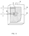
- a coating device shown in Fig. 5 was placed in a room (chamber) in which a water vapor concentration in air was controlled and maintained in the range of more than 0.0076 kg/m 3 .
- the coating device was provided with a cover 18 and an air supply pipe 19 for supplying air having an adjusted water vapor concentration, particularly in a section for forming an organic thin film, so that an artificial increase in the water vapor concentration was inhibited.
- a glass sheet 20 having a bend in part (for example, a glass sheet having a bend extending upward only at the right lower angle is illustrated in Fig. 5) was set in the coating device by hand. The glass sheet was not placed horizontally as in Example 1, but was placed in an obliquely vertical direction.
- a nozzle 21 extended from a side, and the same coating solution as in Example 1 was dropped from the nozzle 21 on a surface of the glass sheet.
- the coating solution was spread uniformly on the surface of the glass sheet with a sponge coater 22 attached to a crossarm extending from a side.
- the nozzle and the sponge coater were simultaneously moved up and down and right and left in concert as shown by an arrow in Fig. 5, spreading the solution uniformly on the glass sheet while dropping it.
- the sponge coater was rotated to enable easy spreading of the coating solution.
- the sponge coater dealt with the bend of the glass sheet by deforming, and made it possible to coat the bend smoothly.
- a dryer 23 having an opening for blowing a dry warm air and a sponge coater 24 different from the above sponge coater were used to form an organic thin film.
- a glass surface of the glass sheet 20 applied with a coating solution was rubbed with the sponge coater, and at the same time a dry warm air was applied thereto so as to form an organic thin film.
- the dryer 23 having an opening for blowing a dry warm air and the sponge coater 24 were simultaneously moved up and down and right and left in concert as shown by an arrow in Fig. 6. Then, the glass sheet 20 was removed by one's hand.
- an organic thin film comprising mainly carbon fluoride was able to be formed on a special shaped glass sheet having a bend in part (e.g. a windshield glass of an automobile).
- Example 1 Although two chambers were used in Example 1, the treatment can be performed with one chamber, if the water vapor concentration can be controlled and maintained, and if the atmosphere does not change when warm air required in the next step is supplied.
- the change of the atmosphere in the chamber also can be accomplished by changing the gas flow rate or the temperature of the substrate.
- changing the gas flow rate it can be accomplished by providing a nozzle near the coating device and supplying air or the like from the nozzle.
- changing the temperature of the substrate it can be accomplished by providing the support with a heating device to increase the temperature of the substrate.
- Example 5 Although a method in which the water vapor concentration in the entire room is controlled and maintained is shown in Example 5, because a change from people coming in and out cannot be dealt with in practive, the cover was provided. The cover was necessary only in this example, and it is not required if the water vapor concentration in the entire room can be controlled with more precision.
- the coating solution was supplied by dropping it with a nozzle in Examples 1 and 5, it also can be supplied as a spray or a mist.
- a film can be formed on an irregular shaped substrate of a large size, and productivity can be improved considerably compared to the conventional immersion method, so that production cost can be reduced considerably. Thus, it has a large industrial value.
- Fig. 7 is a schematic diagram of a rotational coating film-forming apparatus of one example of the present invention.
- an organic thin film can be formed on the inner surface by using a sponge wiper 31 contacting the inner surface and rotating the wiper with a rotational axis 32.
- an organic thin film can be formed by moving the rotational axis 32 up and down to move the wiper 31 up and down.
- the water vapor concentration is controlled and maintained in the range of more than 0.0076 kg/m 3 .
- Fig. 8 is a schematic diagram of a rotational coating film-forming apparatus of one example of the present invention.
- a cylindrical substrate 33 such as a soup container or a glass tumbler as in Example 6
- an organic thin film can be formed on the outer surface by using a cylindrical sponge wiper 34 contacting the outer surface and rotating the wiper with a rotational axis 35.
- a uniform organic thin film can be formed by moving the rotational axis 35 up and down to move the wiper 34 up and down as shown in Fig. 8.
- the agent is supplied by causing it to be absorbed by the wiper as shown in Example 1.
- the water vapor concentration is controlled and maintained in the range of more than 0.0076 kg/m 3 .
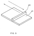
- an organic thin film of the present invention is formed on a flat plate.
- an organic thin film can be formed by using a sponge wiper 40 corresponding to the length of one side of a flat plate 41 and dropping an agent on the flat plate 41 or onto the wiper, and then moving the wiper 40 on the flat plate 41 as shown by an arrow in Fig. 9.
- Other conditions are the same as in Example 1.
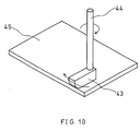
- a uniform organic thin film can be formed by dropping an agent on a flat plate 42 or onto the wiper, and then moving the flat plate 42 while rotating a sponge wiper 43 with a rotational axis 44, or moving the rotational axis 44 back and forth and right and left.
- Other conditions are the same as in Example 1.
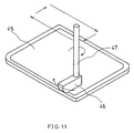
- a uniform organic thin film can be formed by using a sponge wiper 46 as shown in Fig. 11, whose end is curved corresponding to the swelling of the plate, and a rotational axis 47 capable of moving back and forth and right and left as shown by an arrow in Fig. 11.
- an organic thin film also can be formed by moving the flat plate 45 back and forth and right and left, instead of moving the rotational axis 47 back and forth and right and left as in Example 9.
- Other conditions are the same as in Example 1.
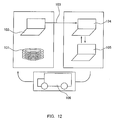
- Fig. 12 shows a flow diagram to explain the following example.
- a restaurant-managing company A owns ceramic and glass products for food and drink (plates (101) are exemplified here), which has been processed for a water repellent surface treatment. Because these products has generated irregularity in the surface treatment, the company A decides to proceed to repair the surface treatment of these products on the next regular holiday.
- the company A transmits a request for repair treatment to a water repellent surface treatment company B through the Internet work 103 as an information transfer system, using a personal computer 102 as an information transmitter.
- the company B receives the request from the company A using a personal computer 104, which is an information receiver present in the company B.
- the company B also can obtain information on the location and method of contact of the company A, and contents of the articles for treatment (e.g. date of the latest treatment, number and materials of the articles owned by the company A, content of the surface treatment, etc.) using a personal computer 105, which is an information processing mechanism present in the company B.
- the company B also prepares to send a product-repair system 106 to the company A on the date specified by the company A.
- the company B provides the product-repair system 106 owned by the company B on the date and at the location specified by the company A.
- the company carries out a surface treatment of the plates 101, which are representative examples of the ceramic and glass products for food and drink requested for treatment by the company A. Then, right after the treatment, the company B delivers the products to the company A.
- the Internet has been described as an example of an information transfer system, as long as the same function can be realized, other methods such as a simple information transfer system using a telephone line etc. also may be used.
- a personal computer also has been described as an example of an information transmitter, as long as the same function can be realized, a digital phone or a digital facsimile etc. also may be used as an information transmitter.
- a personal computer has been described as an example of an information receiver, as long as the same function can be realized, a digital phone or a digital facsimile etc. also may be used as an information receiver.
- Fig. 13 is a scheme of a product-repair system, which comprises a temperature and humidity controlling device 111 and a chlorosilane-based material reaction device 112, and further provided with a product-for-repair supplying device 113 and a product-after-repair collecting device 114.
- the product-for-repair supplying device 113 has a mechanism for conveying a product for repair, which is usually of a belting system. A product for repair can be put in the chlorosilane-based material reaction device 112 by conveyance.
- the chlorosilane-based material reaction device comprises a rubbing film-forming structure, a material-supplying structure, an exhauster and a ventilator.
- the product-after-repair collecting device 114 is of a belting system, and can collect products after repair by conveyance.
- the temperature and humidity controlling device controls the temperature and humidity of the entire product-repair system, and particularly controls strictly the temperature and humidity in the vicinity of the chlorosilane-based material reaction device.
- product-for-repair supplying device 113 and the product-after-repair collecting device 114 have been described as being of a belting system, a roller system or a chuck system also may be employed as needed.
- a rubbing system has been exemplified in the chlorosilane-based material reaction device 112
- the device has a mechanism for spreading an agent uniformly on a substrate such as a spray system or a roll system, such may be substituted.
- a ceramic plate 121 for a surface to be repaired (a plate is herein exemplified as a substrate) is placed on a carrier belt 122, moved under an agent-dropping nozzle 123, and a chlorosilane-based material is dropped from the nozzle 123.
- the dropped chlorosilane-based material is spread uniformly by rotating a rotational jig 124 for application and reaction (the portion of the jig contacting the plate is surrounded with a cloth). At this time, a hydroxyl group having an active hydrogen is exposed in a portion in which a film is peeled and the plate substrate is bared.
- the hydroxyl group and the chlorosilane group of the material cause a hydrogen chloride elimination reaction to generate a chemical bonding with the substrate, so that a film of the material is formed on the portion in which a hydroxyl group is exposed.
- the agent is put on the plate without causing a reaction between the material and the plate.
- an agent for peeling the film is required.
- an alkaline solution is suitably used for the peeling, and a turbid solution containing an abrasive also may be used to remove the film.
- a material other than a chlorosilane-based material it can be removed easily with an organic solvent etc. Then, the above-mentioned film-forming treatment is carried out.
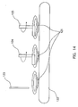
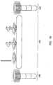
- Fig. 15 is a scheme of a vehicle 131 loaded with a film-repairing apparatus.
- Fig. 16 is a representative schematic diagram of the film-repairing apparatus in the vehicle 131.
- the vehicle loaded with a film-repairing apparatus can repair a film using a chlorosilane-based material, and is in a form of a vehicle, which is movable.
- the film-repairing apparatus loaded on the vehicle 131 comprises a temperature and humidity controlling device and a chlorosilane-based material reaction device 141, and further comprises a product-for-repair supplying device 142 and a product-after-repair collecting device 143.
- the chlorosilane-based material reaction device illustrates the film-forming system shown in Fig. 14 as an example.
Abstract
Description
| Item of Comparative Evaluation | Production Method of Example 1 (Rotational Coating) | Conventional Production Method (Comp. Example 1) (Immersion) |
| Measured Contact Angle (degree) | 110 | 110 |
| Visual Inspection of Appearance | No Adhered Material | White Material Was Adhered |
| Amount of Solution (g) | 0.75 | 1800 |
| Time for Forming a | 20 | 30 minutes |
| Water Vapor Concentration (kg/m3) | 0.002 1 | 0.006 0 | 0.007 6 | 0.015 0 | 0.016 9 | 0.020 3 |
| Number of Possible Fouling Removal | 0 | 2 | 6 | 8 | 6 | 5 |
| Evaluation | x | x | ○ | □ | ○ | ○ |
Claims (9)
- A method for producing an organic film using a compound represented by a general formula (1) ABXn (where A is a carbon-containing group; B is at least one element selected from Si, Ge, Sn, Ti and Zr; X is a hydrolyzable group; and n is 1, 2 or 3 as a raw material, comprising:measuring the compound in an amount required for one time application on a surface of a substrateand supplying it to the predetermined surface of the substrate at each time of application through a nozzle,bringing the compound into contact with the surface of the substrate causing an elimination reaction between an active hydrogen on the surface of the substrate and the hydrolyzable group in parts of the molecules of the compound to the surface;and forming at least two kinds of different surfaces of substrate at one time.
- The method according to claim 1, wherein one of the two kinds of different surfaces of substrate is hydrolyzable with the organic film.
- The method according to claim 1, further comprising washing the substrate and the coating film formed on the substrate after the steps shown in claim 1.
- The method according to claim 1, wherein A in the formula (1) is at least one organic group selected from hydrocarbon groups, fluorocarbon groups, and fluorocarbon hydrocarbon groups.
- The method according to claim 1, wherein X in the formula (1) is a halogen atom.
- The method according to claim 1, wherein the group having an active hydrogen formed on the surface of the substrate is at least one selected from -OH, -NH2, >NH and -COOH groups.
- The method according to claim 1, wherein the chemical reaction is an isocyanic acid elimination reaction, an alcohol elimination reaction, or a halogenohydrogen elimination reaction.
- The method according to claim 1, wherein the formed coating film has a thickness of at least 1 nm but not more than 0.5 µm.
- The method according to claim 1, wherein the substrate is at least one selected from glass, metals, metal oxides, ceramics, polymer compounds, and composites thereof.
Applications Claiming Priority (3)
| Application Number | Priority Date | Filing Date | Title |
|---|---|---|---|
| JP24432299 | 1999-08-31 | ||
| JP24432299 | 1999-08-31 | ||
| EP00117588A EP1080794B1 (en) | 1999-08-31 | 2000-08-16 | Method and apparatus for the production of a coating film |
Related Parent Applications (2)
| Application Number | Title | Priority Date | Filing Date |
|---|---|---|---|
| EP00117588A Division EP1080794B1 (en) | 1999-08-31 | 2000-08-16 | Method and apparatus for the production of a coating film |
| EP00117588.4 Division | 2000-08-16 |
Publications (3)
| Publication Number | Publication Date |
|---|---|
| EP1445034A2 true EP1445034A2 (en) | 2004-08-11 |
| EP1445034A3 EP1445034A3 (en) | 2004-10-06 |
| EP1445034B1 EP1445034B1 (en) | 2006-06-21 |
Family
ID=17117005
Family Applications (3)
| Application Number | Title | Priority Date | Filing Date |
|---|---|---|---|
| EP00117588A Expired - Lifetime EP1080794B1 (en) | 1999-08-31 | 2000-08-16 | Method and apparatus for the production of a coating film |
| EP03022907A Expired - Lifetime EP1382400B1 (en) | 1999-08-31 | 2000-08-16 | Silan-based thin films |
| EP04010197A Expired - Lifetime EP1445034B1 (en) | 1999-08-31 | 2000-08-16 | Method for producing an organic film |
Family Applications Before (2)
| Application Number | Title | Priority Date | Filing Date |
|---|---|---|---|
| EP00117588A Expired - Lifetime EP1080794B1 (en) | 1999-08-31 | 2000-08-16 | Method and apparatus for the production of a coating film |
| EP03022907A Expired - Lifetime EP1382400B1 (en) | 1999-08-31 | 2000-08-16 | Silan-based thin films |
Country Status (6)
| Country | Link |
|---|---|
| US (2) | US6485785B1 (en) |
| EP (3) | EP1080794B1 (en) |
| JP (1) | JP3494622B2 (en) |
| DE (3) | DE60044000D1 (en) |
| DK (2) | DK1445034T3 (en) |
| MY (1) | MY123514A (en) |
Families Citing this family (19)
| Publication number | Priority date | Publication date | Assignee | Title |
|---|---|---|---|---|
| US6809305B2 (en) * | 2002-07-22 | 2004-10-26 | California Institute Of Technology | Microwave bonding of thin film metal coated substrates |
| US8721783B2 (en) * | 2000-06-06 | 2014-05-13 | Dow Corning Corporation | Compositions for treating materials and methods of treating same |
| US7964031B2 (en) * | 2000-06-06 | 2011-06-21 | Dow Corning Corporation | Compositions for treating materials and methods of treating same |
| US6673154B1 (en) * | 2001-06-28 | 2004-01-06 | Advanced Cardiovascular Systems, Inc. | Stent mounting device to coat a stent |
| CA2534820A1 (en) * | 2003-08-19 | 2005-02-24 | The University Of Western Ontario | Method of controllable morphology of self-assembled monolayers on substrates |
| DE10351902A1 (en) * | 2003-11-06 | 2005-06-16 | Damixa A/S | Water-conducting body |
| JP2009512551A (en) * | 2005-10-24 | 2009-03-26 | アキュロン, インコーポレイテッド | Polymeric organometallic film |
| WO2008060583A2 (en) | 2006-11-15 | 2008-05-22 | Aculon, Inc. | Organometallic films, methods for applying organometallic films to substrates and substrates coated with such films |
| JP4668937B2 (en) * | 2007-03-14 | 2011-04-13 | 日本板硝子株式会社 | Method for forming water-repellent film and article coated with water-repellent film |
| US20080276970A1 (en) * | 2007-05-09 | 2008-11-13 | John Christopher Cameron | Apparatus and method for treating materials with compositions |
| JP2009000600A (en) * | 2007-06-20 | 2009-01-08 | Seiko Epson Corp | Pattern forming method, manufacturing method of electro-optical device, and manufacturing method of electronics |
| DE102007040495A1 (en) * | 2007-08-21 | 2009-02-26 | Hansgrohe Ag | plumbing fixture |
| JP5495427B2 (en) * | 2010-03-15 | 2014-05-21 | 第一高周波工業株式会社 | Film formation method |
| KR102563917B1 (en) | 2015-03-20 | 2023-08-04 | 리달, 아이엔씨. | Oleophobic insulating shield and method of making |
| US11059980B2 (en) | 2015-12-02 | 2021-07-13 | Arkema Inc. | Emulsion polymers and stain resistant coating compositions made therefrom |
| EP3383931B1 (en) | 2015-12-02 | 2023-06-28 | Arkema, Inc. | Emulsion polymers and low voc coating compositions made therefrom |
| KR102119717B1 (en) * | 2020-03-17 | 2020-06-08 | 주식회사 나온씨에스 | Coating Method and Apparatus for Outdoor Environment to Prevent Contamination of Photovoltaic Modules |
| CN112519265B (en) * | 2020-11-10 | 2022-07-19 | 苏州金辂房车有限公司 | Production process equipment for glass fiber reinforced plastic for motor home |
| KR102527908B1 (en) * | 2020-11-30 | 2023-05-02 | 주식회사 비케이에너지 | Nano coating manufacturing equipment |
Citations (5)
| Publication number | Priority date | Publication date | Assignee | Title |
|---|---|---|---|---|
| US5011518A (en) * | 1989-03-09 | 1991-04-30 | Matsushita Electric Industrial Co., Ltd. | Permselective membrane and process for producing the same |
| EP0841099A1 (en) * | 1996-11-08 | 1998-05-13 | Matsushita Electric Industrial Co., Ltd | Method and apparatus for producing monomolecular layers |
| EP0848005A2 (en) * | 1996-12-16 | 1998-06-17 | Matsushita Electric Industrial Co., Ltd | Chemically bonding material and method for manufacturing the same |
| EP0854389A1 (en) * | 1997-01-17 | 1998-07-22 | Corning Incorporated | Process for the production of a coating of molecular thickness on a substrate |
| EP1132147A2 (en) * | 1999-02-10 | 2001-09-12 | Matsushita Electric Industrial Co., Ltd. | Organic thin films, process for the production thereof and equipment therefor |
Family Cites Families (17)
| Publication number | Priority date | Publication date | Assignee | Title |
|---|---|---|---|---|
| US3667420A (en) | 1970-10-19 | 1972-06-06 | Eli H Mechling | Frangible target apparatus |
| GB8305217D0 (en) | 1983-02-25 | 1983-03-30 | Sperry Nv | Drive means |
| JPS61122925A (en) | 1984-11-19 | 1986-06-10 | Matsushita Electric Ind Co Ltd | Magnetic recording medium and its production |
| JPS6470917A (en) | 1988-01-29 | 1989-03-16 | Matsushita Electric Ind Co Ltd | Recording medium |
| EP0344799B1 (en) * | 1988-06-03 | 1993-10-13 | Matsushita Electric Industrial Co., Ltd. | Selectively permeable film and process for producing the same |
| US5011578A (en) | 1990-10-24 | 1991-04-30 | Beloit Corporation | Extended nip press apparatus with blanket edge seals |
| CA2054094C (en) * | 1990-10-25 | 1999-12-21 | Kazufumi Ogawa | Chemically adsorbed monomolecular lamination film |
| US5238746A (en) | 1990-11-06 | 1993-08-24 | Matsushita Electric Industrial Co., Ltd. | Fluorocarbon-based polymer lamination coating film and method of manufacturing the same |
| EP0492545B1 (en) | 1990-12-25 | 1998-03-25 | Matsushita Electric Industrial Co., Ltd. | Transparent substrate with monomolecular film thereon and method of manufacturing the same |
| DE69206838T2 (en) * | 1991-02-19 | 1996-05-23 | Matsushita Electric Ind Co Ltd | Process for producing a chemically absorbed film |
| EP0511548B1 (en) * | 1991-04-30 | 1997-07-09 | Matsushita Electric Industrial Co., Ltd. | Chemically adsorbed film and method of manufacturing the same |
| DE69232804T2 (en) * | 1991-04-30 | 2003-01-30 | Matsushita Electric Ind Co Ltd | Hydrophilic chemically adsorbed film and process for its production |
| DE69329536T2 (en) * | 1992-03-02 | 2001-06-07 | Matsushita Electric Ind Co Ltd | Chemically adsorbed film and process for producing the same |
| US5368892A (en) * | 1992-04-10 | 1994-11-29 | Saint-Gobain Vitrage International | Non-wettable glass sheet |
| JPH06310413A (en) | 1993-04-23 | 1994-11-04 | Matsushita Electric Ind Co Ltd | Resist coater and coating method |
| JPH10180179A (en) | 1996-11-08 | 1998-07-07 | Matsushita Electric Ind Co Ltd | Manufacture of molecular film and manufacturing device |
| TW594835B (en) * | 2000-05-09 | 2004-06-21 | Tokyo Electron Ltd | System for coating and developing |
-
2000
- 2000-08-10 US US09/636,225 patent/US6485785B1/en not_active Expired - Lifetime
- 2000-08-12 MY MYPI20003704 patent/MY123514A/en unknown
- 2000-08-16 DE DE60044000T patent/DE60044000D1/en not_active Expired - Lifetime
- 2000-08-16 DE DE60029027T patent/DE60029027T2/en not_active Expired - Lifetime
- 2000-08-16 EP EP00117588A patent/EP1080794B1/en not_active Expired - Lifetime
- 2000-08-16 DE DE60010994T patent/DE60010994T2/en not_active Expired - Lifetime
- 2000-08-16 DK DK04010197T patent/DK1445034T3/en active
- 2000-08-16 DK DK00117588T patent/DK1080794T3/en active
- 2000-08-16 EP EP03022907A patent/EP1382400B1/en not_active Expired - Lifetime
- 2000-08-16 EP EP04010197A patent/EP1445034B1/en not_active Expired - Lifetime
- 2000-08-23 JP JP2000252936A patent/JP3494622B2/en not_active Expired - Lifetime
-
2002
- 2002-09-24 US US10/254,884 patent/US20030104129A1/en not_active Abandoned
Patent Citations (5)
| Publication number | Priority date | Publication date | Assignee | Title |
|---|---|---|---|---|
| US5011518A (en) * | 1989-03-09 | 1991-04-30 | Matsushita Electric Industrial Co., Ltd. | Permselective membrane and process for producing the same |
| EP0841099A1 (en) * | 1996-11-08 | 1998-05-13 | Matsushita Electric Industrial Co., Ltd | Method and apparatus for producing monomolecular layers |
| EP0848005A2 (en) * | 1996-12-16 | 1998-06-17 | Matsushita Electric Industrial Co., Ltd | Chemically bonding material and method for manufacturing the same |
| EP0854389A1 (en) * | 1997-01-17 | 1998-07-22 | Corning Incorporated | Process for the production of a coating of molecular thickness on a substrate |
| EP1132147A2 (en) * | 1999-02-10 | 2001-09-12 | Matsushita Electric Industrial Co., Ltd. | Organic thin films, process for the production thereof and equipment therefor |
Also Published As
| Publication number | Publication date |
|---|---|
| EP1445034A3 (en) | 2004-10-06 |
| EP1080794B1 (en) | 2004-05-26 |
| DK1445034T3 (en) | 2006-07-31 |
| EP1080794A2 (en) | 2001-03-07 |
| EP1382400A3 (en) | 2004-11-17 |
| DE60010994D1 (en) | 2004-07-01 |
| EP1445034B1 (en) | 2006-06-21 |
| EP1080794A3 (en) | 2001-06-13 |
| DE60029027D1 (en) | 2006-08-03 |
| DE60029027T2 (en) | 2006-10-19 |
| MY123514A (en) | 2006-05-31 |
| JP3494622B2 (en) | 2004-02-09 |
| EP1382400B1 (en) | 2010-03-10 |
| US20030104129A1 (en) | 2003-06-05 |
| EP1382400A2 (en) | 2004-01-21 |
| US6485785B1 (en) | 2002-11-26 |
| DK1080794T3 (en) | 2004-08-30 |
| DE60010994T2 (en) | 2005-06-09 |
| JP2001137769A (en) | 2001-05-22 |
| DE60044000D1 (en) | 2010-04-22 |
Similar Documents
| Publication | Publication Date | Title |
|---|---|---|
| EP1445034B1 (en) | Method for producing an organic film | |
| Metwalli et al. | Surface characterizations of mono-, di-, and tri-aminosilane treated glass substrates | |
| US5948476A (en) | Method and apparatus for producing molecular film | |
| JP6254485B2 (en) | Controlled vapor deposition of multilayer coatings bonded by oxide layers | |
| JPH04256466A (en) | Production of organic coating film | |
| Hirai et al. | Mold surface treatment for imprint lithography | |
| US5071709A (en) | Glazing provided with an anti-frost layer | |
| WO2003039855A1 (en) | Article coated with coating film, and functional article coated with coating film using the same | |
| US5665424A (en) | Method for making glass articles having a permanent protective coating | |
| EP0966410A1 (en) | A substrate having a treatment surface | |
| TW422822B (en) | Contamination-resistant float glass and process for producing the same as well as cooking device using said contamination-resistant float glass | |
| JPH10212114A (en) | Formation of sio2 ceramic film | |
| JP5571226B2 (en) | Preparation method of organic thin film on substrate | |
| JP5326782B2 (en) | Method for producing water-repellent article | |
| JP5359529B2 (en) | Method for producing water-repellent article and water-repellent article | |
| WO2005030664A1 (en) | Functional glass article and process for producing the same | |
| US20080318068A1 (en) | Method for the production of a mineral substrate with modified surface and substrate thus obtained | |
| JP3384715B2 (en) | Method for producing protective film and apparatus for producing protective film | |
| JP2577203B2 (en) | Method for producing antifouling glass | |
| KR100492396B1 (en) | A substrate having a treatment surface and surface treating method for a substrate | |
| JP2001170521A (en) | Organic film, method of manufacturing the same and film forming apparatus used therein | |
| JP3387140B2 (en) | Water-repellent glass article | |
| AU736054C (en) | A substrate having a treatment surface | |
| JPH05310444A (en) | Water repellent article and its production |
Legal Events
| Date | Code | Title | Description |
|---|---|---|---|
| PUAI | Public reference made under article 153(3) epc to a published international application that has entered the european phase |
Free format text: ORIGINAL CODE: 0009012 |
|
| 17P | Request for examination filed |
Effective date: 20040429 |
|
| AC | Divisional application: reference to earlier application |
Ref document number: 1080794 Country of ref document: EP Kind code of ref document: P |
|
| AK | Designated contracting states |
Kind code of ref document: A2 Designated state(s): DE DK FR GB IT |
|
| PUAL | Search report despatched |
Free format text: ORIGINAL CODE: 0009013 |
|
| RIN1 | Information on inventor provided before grant (corrected) |
Inventor name: EBISAWA, MITSUO Inventor name: OGAWA, KAZUFUMI Inventor name: OONO, YOSHIAKI Inventor name: MINO, NORIHISA |
|
| AK | Designated contracting states |
Kind code of ref document: A3 Designated state(s): DE DK FR GB IT |
|
| AKX | Designation fees paid |
Designated state(s): DE DK FR GB IT |
|
| 17Q | First examination report despatched |
Effective date: 20050531 |
|
| GRAP | Despatch of communication of intention to grant a patent |
Free format text: ORIGINAL CODE: EPIDOSNIGR1 |
|
| RIN1 | Information on inventor provided before grant (corrected) |
Inventor name: EBISAWA, MITSUO Inventor name: OGAWA, KAZUFUMI Inventor name: MINO, NORIHISA Inventor name: OONO, YOSHIAKI |
|
| GRAS | Grant fee paid |
Free format text: ORIGINAL CODE: EPIDOSNIGR3 |
|
| GRAA | (expected) grant |
Free format text: ORIGINAL CODE: 0009210 |
|
| AC | Divisional application: reference to earlier application |
Ref document number: 1080794 Country of ref document: EP Kind code of ref document: P |
|
| AK | Designated contracting states |
Kind code of ref document: B1 Designated state(s): DE DK FR GB IT |
|
| REG | Reference to a national code |
Ref country code: GB Ref legal event code: FG4D |
|
| REG | Reference to a national code |
Ref country code: DK Ref legal event code: T3 |
|
| REF | Corresponds to: |
Ref document number: 60029027 Country of ref document: DE Date of ref document: 20060803 Kind code of ref document: P |
|
| ET | Fr: translation filed | ||
| PLBE | No opposition filed within time limit |
Free format text: ORIGINAL CODE: 0009261 |
|
| STAA | Information on the status of an ep patent application or granted ep patent |
Free format text: STATUS: NO OPPOSITION FILED WITHIN TIME LIMIT |
|
| 26N | No opposition filed |
Effective date: 20070322 |
|
| REG | Reference to a national code |
Ref country code: FR Ref legal event code: PLFP Year of fee payment: 17 |
|
| REG | Reference to a national code |
Ref country code: FR Ref legal event code: PLFP Year of fee payment: 18 |
|
| PGFP | Annual fee paid to national office [announced via postgrant information from national office to epo] |
Ref country code: DE Payment date: 20170808 Year of fee payment: 18 |
|
| REG | Reference to a national code |
Ref country code: FR Ref legal event code: PLFP Year of fee payment: 19 |
|
| REG | Reference to a national code |
Ref country code: DE Ref legal event code: R119 Ref document number: 60029027 Country of ref document: DE |
|
| PG25 | Lapsed in a contracting state [announced via postgrant information from national office to epo] |
Ref country code: DE Free format text: LAPSE BECAUSE OF NON-PAYMENT OF DUE FEES Effective date: 20190301 |
|
| PGFP | Annual fee paid to national office [announced via postgrant information from national office to epo] |
Ref country code: DK Payment date: 20190813 Year of fee payment: 20 Ref country code: IT Payment date: 20190821 Year of fee payment: 20 Ref country code: FR Payment date: 20190711 Year of fee payment: 20 |
|
| PGFP | Annual fee paid to national office [announced via postgrant information from national office to epo] |
Ref country code: GB Payment date: 20190816 Year of fee payment: 20 |
|
| REG | Reference to a national code |
Ref country code: DK Ref legal event code: EUP Expiry date: 20200816 |
|
| REG | Reference to a national code |
Ref country code: GB Ref legal event code: PE20 Expiry date: 20200815 |
|
| PG25 | Lapsed in a contracting state [announced via postgrant information from national office to epo] |
Ref country code: GB Free format text: LAPSE BECAUSE OF EXPIRATION OF PROTECTION Effective date: 20200815 |