EP2746484A1 - Building element for thermal and/or sound insulation of a building facade - Google Patents
Building element for thermal and/or sound insulation of a building facade Download PDFInfo
- Publication number
- EP2746484A1 EP2746484A1 EP20120198242 EP12198242A EP2746484A1 EP 2746484 A1 EP2746484 A1 EP 2746484A1 EP 20120198242 EP20120198242 EP 20120198242 EP 12198242 A EP12198242 A EP 12198242A EP 2746484 A1 EP2746484 A1 EP 2746484A1
- Authority
- EP
- European Patent Office
- Prior art keywords
- building
- elements
- rigid
- integrated joint
- insulating
- Prior art date
- Legal status (The legal status is an assumption and is not a legal conclusion. Google has not performed a legal analysis and makes no representation as to the accuracy of the status listed.)
- Withdrawn
Links
- 238000009413 insulation Methods 0.000 title claims abstract description 20
- 239000002184 metal Substances 0.000 claims abstract description 22
- 229910052500 inorganic mineral Inorganic materials 0.000 claims abstract description 19
- 239000011707 mineral Substances 0.000 claims abstract description 19
- 239000011230 binding agent Substances 0.000 claims abstract description 12
- 230000001681 protective effect Effects 0.000 claims description 36
- 239000000853 adhesive Substances 0.000 claims description 22
- 230000001070 adhesive effect Effects 0.000 claims description 22
- 230000000087 stabilizing effect Effects 0.000 claims description 11
- 239000000835 fiber Substances 0.000 claims description 8
- 230000003014 reinforcing effect Effects 0.000 claims description 7
- 238000004026 adhesive bonding Methods 0.000 claims description 3
- 238000005452 bending Methods 0.000 claims description 3
- 239000011347 resin Substances 0.000 claims description 3
- 229920005989 resin Polymers 0.000 claims description 3
- 239000002245 particle Substances 0.000 description 8
- 239000004964 aerogel Substances 0.000 description 7
- 230000000694 effects Effects 0.000 description 6
- 229910000831 Steel Inorganic materials 0.000 description 5
- 238000010276 construction Methods 0.000 description 5
- 239000010959 steel Substances 0.000 description 5
- 230000004888 barrier function Effects 0.000 description 4
- 239000011796 hollow space material Substances 0.000 description 4
- 239000012774 insulation material Substances 0.000 description 4
- 239000011490 mineral wool Substances 0.000 description 4
- 230000006835 compression Effects 0.000 description 3
- 238000007906 compression Methods 0.000 description 3
- 238000004519 manufacturing process Methods 0.000 description 3
- 229920002994 synthetic fiber Polymers 0.000 description 3
- XLYOFNOQVPJJNP-UHFFFAOYSA-N water Substances O XLYOFNOQVPJJNP-UHFFFAOYSA-N 0.000 description 3
- 239000010425 asbestos Substances 0.000 description 2
- 239000006260 foam Substances 0.000 description 2
- 239000000463 material Substances 0.000 description 2
- 229910052895 riebeckite Inorganic materials 0.000 description 2
- 238000009435 building construction Methods 0.000 description 1
- 239000004568 cement Substances 0.000 description 1
- 238000001816 cooling Methods 0.000 description 1
- 239000004744 fabric Substances 0.000 description 1
- 239000011888 foil Substances 0.000 description 1
- 239000003365 glass fiber Substances 0.000 description 1
- 230000002209 hydrophobic effect Effects 0.000 description 1
- 238000009434 installation Methods 0.000 description 1
- 239000011810 insulating material Substances 0.000 description 1
- 239000000203 mixture Substances 0.000 description 1
- 230000000149 penetrating effect Effects 0.000 description 1
- 210000002105 tongue Anatomy 0.000 description 1
- 210000002268 wool Anatomy 0.000 description 1
Images


Classifications
-
- E—FIXED CONSTRUCTIONS
- E04—BUILDING
- E04B—GENERAL BUILDING CONSTRUCTIONS; WALLS, e.g. PARTITIONS; ROOFS; FLOORS; CEILINGS; INSULATION OR OTHER PROTECTION OF BUILDINGS
- E04B1/00—Constructions in general; Structures which are not restricted either to walls, e.g. partitions, or floors or ceilings or roofs
- E04B1/38—Connections for building structures in general
- E04B1/61—Connections for building structures in general of slab-shaped building elements with each other
- E04B1/6108—Connections for building structures in general of slab-shaped building elements with each other the frontal surfaces of the slabs connected together
- E04B1/612—Connections for building structures in general of slab-shaped building elements with each other the frontal surfaces of the slabs connected together by means between frontal surfaces
- E04B1/6145—Connections for building structures in general of slab-shaped building elements with each other the frontal surfaces of the slabs connected together by means between frontal surfaces with recesses in both frontal surfaces co-operating with an additional connecting element
- E04B1/6158—Connections for building structures in general of slab-shaped building elements with each other the frontal surfaces of the slabs connected together by means between frontal surfaces with recesses in both frontal surfaces co-operating with an additional connecting element the connection made by formlocking
-
- E—FIXED CONSTRUCTIONS
- E04—BUILDING
- E04B—GENERAL BUILDING CONSTRUCTIONS; WALLS, e.g. PARTITIONS; ROOFS; FLOORS; CEILINGS; INSULATION OR OTHER PROTECTION OF BUILDINGS
- E04B1/00—Constructions in general; Structures which are not restricted either to walls, e.g. partitions, or floors or ceilings or roofs
- E04B1/38—Connections for building structures in general
- E04B1/61—Connections for building structures in general of slab-shaped building elements with each other
- E04B1/6108—Connections for building structures in general of slab-shaped building elements with each other the frontal surfaces of the slabs connected together
- E04B1/612—Connections for building structures in general of slab-shaped building elements with each other the frontal surfaces of the slabs connected together by means between frontal surfaces
- E04B1/6145—Connections for building structures in general of slab-shaped building elements with each other the frontal surfaces of the slabs connected together by means between frontal surfaces with recesses in both frontal surfaces co-operating with an additional connecting element
- E04B1/6162—Connections for building structures in general of slab-shaped building elements with each other the frontal surfaces of the slabs connected together by means between frontal surfaces with recesses in both frontal surfaces co-operating with an additional connecting element the connection made by an additional locking key
-
- E—FIXED CONSTRUCTIONS
- E04—BUILDING
- E04C—STRUCTURAL ELEMENTS; BUILDING MATERIALS
- E04C2/00—Building elements of relatively thin form for the construction of parts of buildings, e.g. sheet materials, slabs, or panels
- E04C2/02—Building elements of relatively thin form for the construction of parts of buildings, e.g. sheet materials, slabs, or panels characterised by specified materials
- E04C2/26—Building elements of relatively thin form for the construction of parts of buildings, e.g. sheet materials, slabs, or panels characterised by specified materials composed of materials covered by two or more of groups E04C2/04, E04C2/08, E04C2/10 or of materials covered by one of these groups with a material not specified in one of the groups
- E04C2/284—Building elements of relatively thin form for the construction of parts of buildings, e.g. sheet materials, slabs, or panels characterised by specified materials composed of materials covered by two or more of groups E04C2/04, E04C2/08, E04C2/10 or of materials covered by one of these groups with a material not specified in one of the groups at least one of the materials being insulating
- E04C2/292—Building elements of relatively thin form for the construction of parts of buildings, e.g. sheet materials, slabs, or panels characterised by specified materials composed of materials covered by two or more of groups E04C2/04, E04C2/08, E04C2/10 or of materials covered by one of these groups with a material not specified in one of the groups at least one of the materials being insulating composed of insulating material and sheet metal
-
- E—FIXED CONSTRUCTIONS
- E04—BUILDING
- E04C—STRUCTURAL ELEMENTS; BUILDING MATERIALS
- E04C2/00—Building elements of relatively thin form for the construction of parts of buildings, e.g. sheet materials, slabs, or panels
- E04C2/30—Building elements of relatively thin form for the construction of parts of buildings, e.g. sheet materials, slabs, or panels characterised by the shape or structure
- E04C2/38—Building elements of relatively thin form for the construction of parts of buildings, e.g. sheet materials, slabs, or panels characterised by the shape or structure with attached ribs, flanges, or the like, e.g. framed panels
- E04C2/384—Building elements of relatively thin form for the construction of parts of buildings, e.g. sheet materials, slabs, or panels characterised by the shape or structure with attached ribs, flanges, or the like, e.g. framed panels with a metal frame
-
- E—FIXED CONSTRUCTIONS
- E04—BUILDING
- E04C—STRUCTURAL ELEMENTS; BUILDING MATERIALS
- E04C2/00—Building elements of relatively thin form for the construction of parts of buildings, e.g. sheet materials, slabs, or panels
- E04C2002/001—Mechanical features of panels
- E04C2002/004—Panels with profiled edges, e.g. stepped, serrated
Definitions
- the invention relates to a building element, especially a wall element for thermal and/or sound insulation of a building façade, consisting of an insulating element comprising two large surfaces extending substantially parallel and with a distance to each other and four lateral surfaces extending substantially at right angles to the large surfaces, and a frame made of sheet metal and being arranged at least at two lateral surfaces being arranged at opposite sides of the insulating element.
- sandwich panel systems consist of sandwich panels which are put together to build up a part of a building, for example a building façade, a wall or a roof.
- Each sandwich panel consists of at least one layer made of insulation material especially a foam being arranged between two layers of sheet metal which are connected to the layer of insulation material giving the necessary stability.
- the sheet metal is arranged on top of the two large surfaces.
- the four lateral surfaces can be provided with a sheet metal so that the layer of insulation material is totally encapsulated into a construction of sheet metal.
- US 1 697 189 discloses a heat insulating structural panel for use in building commercial ovens as well as for constructing refrigerating or cooling chambers formed with sheet metal sides and reinforced corners comprising steel angle strips about which the edges of the sides are turned and clamped to provide tongues.
- the sidewalls are secured in spaced relations so as to form a hollow enclosing structure by means of strips of hard heat insulating material which may be prepared of cement and asbestos fibre or any other suitable composition or material.
- the edge structure of the panel being uniform along the four sides forms a chamber which is adapted to be filled with insulation material such as asbestos fibres or any other suitable material, the choice of which will be given largely by the purpose for which the panels are to be used.
- this object is achieved with a building element having an insulating element made of mineral fibres and a frame having at least two integrated joint elements being load bearing and arranged at opposite sides of the insulating element and formed correspondingly to each other wherein at least one integrated joint element comprising a rigid element being fixed in a clamp fit way to the frame, having thermal and/or sound insulation characteristics and being made of mineral fibres and binder with a bulk density being higher than a bulk density of the insulating element, preferably of at least 180 kg/m 3 .
- Such a building element especially a wall element for thermal and/or sound insulation of a building façade has a joint design which will transport all loads to the frame having at least two integrated joint elements without the need of traditional supports between beams. This is achieved because the compression forces are covered by specific load bearing and thermal bridge free systems along the whole element joints.
- the area for the compression load/force is increased and therefore the compression of the insulating element can be reduced significantly so that an insulating element made of mineral fibres with lower bulk density can be used.
- the result of using an insulating element made of mineral fibres with lower bulk density is that the insulation properties are increased. Because of the combination of all features of the building element according to the invention such building elements can be produced with lengths up to more than 12 meters.
- building elements can be handled easily because of the reduced weight of the insulting element made of mineral fibres.
- building elements can be provided with sheet metal on top of the large surfaces.
- the building element according to the invention allows to use covering layers made of resin being connected to the frame so that the insulating element made of mineral fibres is encapsulated into the frame and the layers being arranged on top of the large surfaces of the insulating element.
- Building elements according to the prior art always need profiled steel supports between the building beams which have a distance of about 3 to 6 meters. These steel supports have the function to take over all loads from the building elements and transfer them into the building construction.
- a building element according to the invention has the advantage that all loads are directly given to the building beams because the building elements themselves secure the safe load bearing effect through the integrated joint elements. According to the invention the "sandwich effect" works crosswise to the building element and the integrated joint elements are substituting the steel supports behind the building elements according to the prior art so that the building element according to the invention allows to build up thermal bridge free systems easily.
- the integrated joint elements are mainly u-shaped with two legs being oriented mainly parallel and arranged spaced apart from each other and with the rigid element being arranged between the legs.
- the rigid element which is fixed in a clamp fit way between the legs of the integrated joint element consists of components fibres, aerogel particles and at least one binder, whereby 20 to 40 wt% mineral wool fibres, 45 to 70 wt% aerogel particles and 8 to 12 wt% binder are pressed and cured to a board having a density of 130 kg/m 3 to 200 kg/m 3 , preferably of at least 180 kg/m 3 .
- Such a rigid element can have a thermal conductivity A of less than 0.022 W/(mK).
- aerogel particles hydrophobic aerogel particles and up to 10 wt% binder are mixed and are shaped to a board which is finally cured.
- a board contains 50 to 70 wt% areogel particles and up to 30 wt% mineral fibres.
- the rigid element is fixed to the insulating element and/or the integrated joint elements at least by gluing.
- Gluing the rigid element to the insulating element and/or the integrated joint elements avoids fastening elements like screws, rivets or the like. Therefore, thermal bridges can be avoided easily.
- a vapor barrier and/or a tensile element is arranged between the rigid element and the insulating element.
- the vapor barrier hinders humidity to get into the insulating element.
- the tensile element stiffens the rigid element and the insulating element in their contact zone.
- the insulating element has a fibre orientation direct between the integrated joint elements.
- the fibre orientation has on one hand an effect on the stiffness of the building element and on the other hand an effect on the insulation properties of the insulating element being arranged in the frame.
- the fibre orientation as described before increases the insulation properties of the building element.
- one leg of the integrated joint element is formed as an u-shaped recess in which a stabilizing element can be incorporated, which is preferably made of a bar having a length being at least equal to the length of the insulating element.
- a stabilizing element can be incorporated, which is preferably made of a bar having a length being at least equal to the length of the insulating element.
- the stabilizing element is H-shaped in cross section.
- the stabilizing element can for example be used to carry conduits for water, gas or electric energy.
- the two legs of at least one integrated joint element are connectable by at least one tension rod, especially at least one screw which is or which are oriented perpendicular to the legs of the integrated joint element.
- This tension rod allows to build up a tension between the spaced apart legs of the integrated joint to fix two neighbored building elements by building up friction forces and/or to fix the stabilizing element by building up friction forces between the stabilizing element and at least one leg of the integrated joint element.
- the tension rod is made of a resin being tension resistant to avoid a thermal bridge between the two spaced apart legs of the integrated joint element.
- the rigid element has two main surfaces of which one main surface is connected directly or indirectly to the lateral surface of the insulating element, whereby the two main surfaces of the rigid element are diverging to each other.
- This embodiment has the advantage to build up increased water tightness.
- the rigid element has a main surface being capable to be connected with an adhesive.
- the rigid element according to the invention comprises at least one board of mineral fibres and two protective elements, each being fixed to and covering at least partly one main surface and one lateral surface of the board whereby the protective elements are not in direct contact to each other.
- the rigid element has an increased stiffness and does not build up a thermal bridge between the outer surfaces of the building element because of the missing contact between the two protective elements which may be made from metal.
- the two protective elements are overlapping each other on opposed main surfaces of the board.
- the protective elements have a L-, U- or T-shape in cross section. An effective section modulus can be achieved.
- two protective elements are connected to each other by connecting means like rivets, screws or the like which run perpendicular to the main surfaces of the boards.
- two boards are connected by at least one clamp like protective element which fixes the two boards to each other.
- the invention relates to a building having at least two building elements, preferably as wall elements for thermal and/or sound insulation of a building façade, each building element consisting of an insulating element made of mineral fibres, comprising two large surfaces extending substantially parallel and with a distance to each other and four lateral surfaces extending substantially at right angles to the large surfaces, and a frame made of sheet metal and being arranged at least at two lateral surfaces being arranged at opposite sides of the insulating element, wherein the frame has integrated joint elements being formed correspondingly to each other and load bearing and wherein at least one integrated joint element comprises a rigid element having thermal and/or sound insulation characteristics and being made of mineral fibres and a binder.
- corresponding integrated joint elements of the building elements are connected to each other in form fitted way and by an adhesive being provided between two rigid elements of the building elements facing to each other.
- the adhesive between the rigid elements is non-combustible.
- the rigid elements are preferably connected to the insulating element and/or the integrated joint elements by an adhesive, preferably with an incorporated vapor barrier and/or a tensile element, for example a fibrous web.
- each integrated joint element has at least two legs extending parallel to each other and being made from the sheet metal of the frame, which is connected to the insulating element, especially to the main surfaces of the insulating element and in that each leg is formed by bending a free end of the sheet metal.
- the building element can be developed in the inventive way in incorporating one or all features which are already described above with reference to the building element.
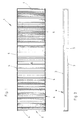
- Fig. 1 shows a building element 1 in form of a wall element for thermal and/or sound insulation of a building façade.
- the building element 1 consists of an insulating element 2 made of mineral wool fibres and a binder having a bulk density of 80 kg/m 3 .
- the insulating element 2 has two large surfaces 3 of which one can be seen in Fig. 1 .
- the insulating element has four lateral surfaces 4 each being arranged perpendicular to the large surfaces 3. From Fig. 1 it can be seen that the insulating element 2 and therefore the building element 1 has two long lateral surfaces 4 running parallel to each other as well as two short lateral surfaces running parallel to each other and perpendicular to the long lateral surfaces 4.
- layers 5 Fixed to the longer lateral surfaces 4 are layers 5 made of sheet metal and building up a frame being arranged at two lateral surfaces 4 at opposite sides of the insulating element 2. Of course such layers 5 can also be provided at the shorter lateral surfaces 4. The layers 5 forming load bearing joint elements 6 which can be seen more precisely in Fig. 3 to 8 .
- the layers 5 at the opposite lateral surfaces 4 have different shapes as can be seen from Fig. 3 which will be described in the following.
- the large surfaces 3 of the insulating element 2 are covered with a layer 7 made from sheet metal or for example from synthetic material having a high bending strength and/or shear strength.
- the layer 7 is made of sheet metal offering these characteristics as mentioned before.
- the layer 7 has a bigger length than the length of the insulating element 2. Therefore, the layer 7 extends over the large surface 3 of the insulation element 2.
- the part of the layer 7 extending over the insulating element 2 is bent twice so that a free leg 8 of the layer 7 erects parallel to the layer 7 whereby between the free leg 8 and the layer 7 an open cavity is formed.
- the layer In the area of the second large surface 3 of the building element 1 the layer is formed in a S-shape so that additional in this area the layer 7 forms together with a leg 9 an open cavity.
- the leg 9 is bent twice in perpendicular directions.
- a cavity 11 is formed between the leg 9 and a free leg 10 of the layer 7.
- a reinforcing element 12 which is a more or less vapor-proof barrier and for example made of a glass fibre fabric or a foil is arranged in the cavities between the free leg 8 and the layer 7 on the first large surface 3 and between the leg 9 and the layer 7 on the second large surface 3.
- the reinforcing element 12 erects starting from the two cavities as described before parallel to a lateral surface 4 of the insulation element 2. Furthermore, the reinforcing element 12 is fixed with an adhesive inside the cavities as well as to the lateral surface 4.
- a rigid element 13 is arranged between the two legs 8 and 10. This rigid element 13 is fixed to the legs 8, 10 with an adhesive as well as with the reinforcing element 12.
- the rigid element 13 is fixed in a clamp fit way between the legs of the integrated joint element 6 being formed by at least the legs 8 and 10.
- the rigid element 13 consists of fibres, aerogel particles and at least one binder, whereby 30 wt% mineral wool fibres, 60 wt% aerogel particles and 10 wt% binder are pressed and cured to a board having a density of 190 kg/m 3 .
- This rigid element 13 has a thermal conductivity A of 0.02 W/(mK).
- FIG. 3 two building elements 1 which have to be put together as it is shown in Fig. 4 , Fig. 5 and Fig. 6 have two differently shaped load bearing joint elements 6.
- the differences between the two load bearing joint elements 6 of two building elements 1 which should fit together is restricted to the arrangement of the leg 8.
- the load bearing joint element 6 on one lateral surface 4 spans the total length of the lateral surface 4 whereas the second load bearing joint element 6 is shorter than the width of the lateral surface 4 so that a recess 14 is provided into which the leg 8 of the load bearing joint element 6 of the neighbored building element 1 engages.
- two building elements 1 according to Fig. 3 can be clamp fitted and that most of load will be borne in the frame having two load bearing joint elements 6 which are connected to each other by the layers 7 so that the insulating element 2 can be reduced in bulk density.
- an insulating element 2 made of wool with a certain fibre orientation so that an insulating element 2 can be used made from mineral wool with a fibre orientation parallel to their large surfaces which may be in production the cheapest insulating element 2.
- the insulating element 2 can have a certain fibre orientation for example perpendicular to the lateral surfaces 4 provided with the load bearing joint elements 6 to increase the compressive strength of the insulating element as well as of the building element 1 in a direction parallel to the large surfaces 3 of the insulating element 2.
- each rigid element 13 has a planar surface 15 being suitable to adjust an adhesive 16 which is used to connect both rigid elements 13 being arranged within the load bearing joint elements 6 of neighbored building elements 1. It can be seen that the building elements 1 according to Fig. 3 are connected to each other without any mechanical fastener only by using a press fit and an adhesive 16, which is non combustible.
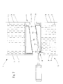
- Fig. 4 shows the two building elements 1 according to Fig. 3 in a connected position.
- the two cavities 11 together form a hollow space with an opening 17 through which a beam 18 span.
- the beam 18 is a stabilizing element and is H-shaped in cross section having two side legs 19 being connected via a bar 20.
- One of the side legs 19 is encapsulated within the two cavities 11.
- the beam 18 can be used to stiffen the connection of the two building elements 1 being arranged neighbored to each other in that the beam 18 runs at least nearly over the whole length of the building elements 1, preferably in that the beam 18 spans the building elements 1 being arranged lengthwise.
- the beam 18 can be used to carry conduits 21 for water, gas or electric energy as it is shown in Fig. 5 .
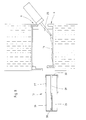
- Fig. 5 shows a cover 22 which is fixed to the beam 18 and/or the building element 1 and which covers the beam 18 with the conduits 21 so that the conduits 21 are protected by the cover 22.
- the hollow space 17 can be closed with a profile element 23 being T-shaped in cross section and preferably made of synthetic material which allows to clamp fit the profile element 23 into the opening of the hollow space 17 between two neighbored building elements 1.
- a profile element 23 is shown in Fig. 6 .
- a further stabilizing element is shown in Fig. 5 in form of a screw 24 which spans through the rigid element 13 connecting both legs 8 and 9 of one load bearing joint element 6 with each other. It can be seen from Fig. 5 that the screw 24 passes through one side leg 19 of the beam 18.
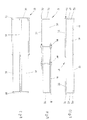
- Fig. 7 shows a further embodiment of two building elements 1 shortly before they are connected to each other.
- This embodiment shows two building elements 1 which are in main aspects identical to the building element 1 as shown in Fig. 1 to 6 and described before.
- the difference between the embodiments can be seen in the construction of the rigid elements 13 being inserted into the load bearing joint elements 6.
- These rigid elements 13 have two main surfaces of which one main surface 15 is connected to the lateral surface 4 of the insulating element 2 by means of an adhesive, whereby the second main surface 15 of the rigid element 13 is diverging to the first main surface which is connected to the insulating element 2.
- This embodiment has the advantage that penetrating humidity can be diverted in the direction of a descent being provided by the two main surfaces 15 of the two rigid elements 13 being connected to each other.
- FIG. 8 shows two building elements 1 and it can be seen that one singular rigid element 13 is used to be inserted into a cavity 25 built up by two load bearing joint elements 6 of two building elements 1 being arranged neighbored to each other.
- the construction of the load bearing joint elements 6 corresponds to the construction of the load bearing joint elements 6 according to the embodiments described before.
- the rigid element 13 is prepared and comprises two boards of mineral fibres, aerogel particles and a binder as described before in view of the rigid elements 13 shown in Fig. 3 to 7 .
- the boards 26 are connected to each other by two protective elements 27, 28 of different shape.
- the protective element 27 is made of sheet metal and u-shaped in cross section. Therefore, the protective element 27 has two legs erecting parallel to each other and connected to each other by a web being oriented rectangular to the legs. The distance between the two legs of the protective element 27 is equal to the thickness of the two boards 26 which are glued together by an adhesive 29. Furthermore, the adhesive 29 is provided between the main surfaces and the legs of the protective element 27 as well as between the lateral surfaces of the boards 26 and the web 30 of the protective element 27.
- the second protective element 28 is made of sheet metal and is T-shaped in cross section.
- the second protective element 28 is arranged at the boards 26 opposite to the protective element 27 whereby the two lateral surfaces of the boards 26 are totally covered by a first leg of the protective element 28 and whereas the second leg of the protective element 28 spans between the two boards 26.
- the two protective elements 27, 28 are not in contact with each other so that the rigid element 13 according to Fig. 8 does not constitute a thermal bridge between the two outer sides of the building elements 1.
- the rigid element 13 is inserted into the cavity 25 and fixed by the adhesive 16 to the load bearing joint elements 6 whereby the adhesive 16 is arranged at least on the big surfaces of the load bearing joint elements 6 before the rigid element 13 is inserted into a load bearing joint element 6 of one building element and the second building element 1 is put on top of the building element 1 already containing the rigid element 13.
- the invention is not limited with respect to the embodiment according to Fig. 8 to the construction of the rigid element 13 as shown in Fig. 8 and 9 .
- FIG. 10 and 11 show two further embodiments of a rigid element 13 which will be described hereafter.
- the rigid element 13 consists of one board 26 and protection elements 31 being u-shaped in cross section and therefore having two legs 32, 33 and a connecting web 34.
- the legs 32 are longer than the legs 33.
- the web 34 is connected to lateral surfaces of the board 26.
- an adhesive is arranged between the protective elements 31 and the board 26. It can be seen from Fig. 10 that the longer legs 32 of the two protective elements 31 are connected to opposite main surfaces of the board 26.
- the length of the two legs 32 of the protective elements 31 is slightly bigger than half of the width of the protective element 23.
- FIG. 11 Further embodiment of the rigid element 13 is shown in Fig. 11 .
- This embodiment of the rigid element 13 consists of the board 26 and two protective elements which are L-shaped in cross section and having therefore a longer leg 36 and a shorter leg 37 being oriented perpendicular to each other.
- the longer legs 36 of the protective elements 35 cover the main surfaces of the rigid element 13.
- the length of the longer legs is shorter than the width of the board 26 but longer than half of the width of the board 26 so that both legs 36 of the two protective elements 35 can be easily connected by screws 38 made of synthetic material. Instead of screws 38 rivets can be used.
- the before described building element 1 according to the invention has the big advantage that loads can be given directly to building beams because the building element itself secures the safe load bearing effect through the load bearing joint elements 6 in combination with the rigid elements 13. Therefore, the sandwich effect works crosswise to the length of the building elements 1 with a short span of 2 meters up to 2,5 meters which is a usual width of a production line for the production of insulating elements 2.
- the integrated load bearing joint elements 6 are substituting the normally necessary steel supports behind the building elements 1.
- the new building elements 1 therefore allow thermal bridge free systems.
- the new building elements 1 and buildings being built up with these building elements 1 are achieved by using adhesives 16, 29 in various areas of the building elements 1.
- the use of adhesives 16, 29 makes it possible to reduce or to avoid screwing and dynamic loads are covered in a much better way along the whole building elements 1 and not only punctual. Therefore, the invention provides a new building element 1 for example for all non residential buildings with new possible designs.
- the new building elements 1 can at least be produced easily and have of course a better fire resistance compared to building elements 1 having a filling of foam. Because of the reduced density of the insulating element 2 being inserted into the building element 1 low thermal conductivity of ⁇ ⁇ 35 mW/(mK) can be achieved.
- the building elements 1 can be produced in bigger units because the reduction of the bulk density of the insulating element 2 made of mineral fibres has the advantage of less weight. Bigger units have the advantage of a faster installation. Therefore, the invention has the advantages of fire safety, better acoustical performance, better energy efficiency and real sustainability.
- the building element 1 can have layers made of sheet metal with a profiling erecting parallel to the width of the building element 1. Building element 1 with lengths up to 12 m and widths up to 2.5 m are possible.
Abstract
The invention relates to a building element, especially wall element for thermal and/or sound insulation of a building facade, comprising an insulating element made of mineral fibres, comprising two large surfaces extending substantially parallel and with a distance to each other and four lateral surfaces extending substantially at right angles to the large surfaces, and a frame made of sheet metal and being arranged at least at two lateral surfaces being arranged at opposite sides of the insulating element, wherein the frame has at least two integrated joint elements being load bearing and arranged at the opposite sides of the insulating element and formed correspondingly to each other and wherein at least one integrated joint element comprises a rigid element being fixed to the frame, having thermal and/or sound insulation characteristics and being made of mineral fibres and a binder with a bulk density being higher than a bulk density of the insulating element, preferably of at least 180kg/m3.
Description
- The invention relates to a building element, especially a wall element for thermal and/or sound insulation of a building façade, consisting of an insulating element comprising two large surfaces extending substantially parallel and with a distance to each other and four lateral surfaces extending substantially at right angles to the large surfaces, and a frame made of sheet metal and being arranged at least at two lateral surfaces being arranged at opposite sides of the insulating element.
- A great number of so called sandwich panel systems is well known. Such sandwich panel systems consist of sandwich panels which are put together to build up a part of a building, for example a building façade, a wall or a roof. Each sandwich panel consists of at least one layer made of insulation material especially a foam being arranged between two layers of sheet metal which are connected to the layer of insulation material giving the necessary stability. The sheet metal is arranged on top of the two large surfaces. Furthermore, the four lateral surfaces can be provided with a sheet metal so that the layer of insulation material is totally encapsulated into a construction of sheet metal.
-
US 1 697 189 discloses a heat insulating structural panel for use in building commercial ovens as well as for constructing refrigerating or cooling chambers formed with sheet metal sides and reinforced corners comprising steel angle strips about which the edges of the sides are turned and clamped to provide tongues. The sidewalls are secured in spaced relations so as to form a hollow enclosing structure by means of strips of hard heat insulating material which may be prepared of cement and asbestos fibre or any other suitable composition or material. The edge structure of the panel being uniform along the four sides forms a chamber which is adapted to be filled with insulation material such as asbestos fibres or any other suitable material, the choice of which will be given largely by the purpose for which the panels are to be used. - It is one object of the invention to provide a building element which is easy to handle, easy to produce and which has high insulation and stability properties.
- According to the invention this object is achieved with a building element having an insulating element made of mineral fibres and a frame having at least two integrated joint elements being load bearing and arranged at opposite sides of the insulating element and formed correspondingly to each other wherein at least one integrated joint element comprising a rigid element being fixed in a clamp fit way to the frame, having thermal and/or sound insulation characteristics and being made of mineral fibres and binder with a bulk density being higher than a bulk density of the insulating element, preferably of at least 180 kg/m3.
- Such a building element, especially a wall element for thermal and/or sound insulation of a building façade has a joint design which will transport all loads to the frame having at least two integrated joint elements without the need of traditional supports between beams. This is achieved because the compression forces are covered by specific load bearing and thermal bridge free systems along the whole element joints. The area for the compression load/force is increased and therefore the compression of the insulating element can be reduced significantly so that an insulating element made of mineral fibres with lower bulk density can be used. The result of using an insulating element made of mineral fibres with lower bulk density is that the insulation properties are increased. Because of the combination of all features of the building element according to the invention such building elements can be produced with lengths up to more than 12 meters. Such building elements can be handled easily because of the reduced weight of the insulting element made of mineral fibres. Of course such building elements can be provided with sheet metal on top of the large surfaces. Nevertheless, the building element according to the invention allows to use covering layers made of resin being connected to the frame so that the insulating element made of mineral fibres is encapsulated into the frame and the layers being arranged on top of the large surfaces of the insulating element.
- Building elements according to the prior art always need profiled steel supports between the building beams which have a distance of about 3 to 6 meters. These steel supports have the function to take over all loads from the building elements and transfer them into the building construction. A building element according to the invention has the advantage that all loads are directly given to the building beams because the building elements themselves secure the safe load bearing effect through the integrated joint elements. According to the invention the "sandwich effect" works crosswise to the building element and the integrated joint elements are substituting the steel supports behind the building elements according to the prior art so that the building element according to the invention allows to build up thermal bridge free systems easily.
- According to a further feature of the invention the integrated joint elements are mainly u-shaped with two legs being oriented mainly parallel and arranged spaced apart from each other and with the rigid element being arranged between the legs. Preferably the rigid element which is fixed in a clamp fit way between the legs of the integrated joint element consists of components fibres, aerogel particles and at least one binder, whereby 20 to 40 wt% mineral wool fibres, 45 to 70 wt% aerogel particles and 8 to 12 wt% binder are pressed and cured to a board having a density of 130 kg/m3 to 200 kg/m3, preferably of at least 180 kg/m3. Such a rigid element can have a thermal conductivity A of less than 0.022 W/(mK). As aerogel particles hydrophobic aerogel particles and up to 10 wt% binder are mixed and are shaped to a board which is finally cured. Such a board contains 50 to 70 wt% areogel particles and up to 30 wt% mineral fibres.
- Preferably the rigid element is fixed to the insulating element and/or the integrated joint elements at least by gluing. Gluing the rigid element to the insulating element and/or the integrated joint elements avoids fastening elements like screws, rivets or the like. Therefore, thermal bridges can be avoided easily.
- According to a further feature of the invention a vapor barrier and/or a tensile element is arranged between the rigid element and the insulating element. The vapor barrier hinders humidity to get into the insulating element. The tensile element stiffens the rigid element and the insulating element in their contact zone. Preferably the insulating element has a fibre orientation direct between the integrated joint elements. The fibre orientation has on one hand an effect on the stiffness of the building element and on the other hand an effect on the insulation properties of the insulating element being arranged in the frame. The fibre orientation as described before increases the insulation properties of the building element.
- According to a further feature of the invention one leg of the integrated joint element is formed as an u-shaped recess in which a stabilizing element can be incorporated, which is preferably made of a bar having a length being at least equal to the length of the insulating element. Preferably the stabilizing element is H-shaped in cross section. The stabilizing element can for example be used to carry conduits for water, gas or electric energy. In this case it is preferred to have a cover which is arranged outside of the building element and fixed to an free end of the stabilizing element covering the free end of the stabilizing element up the outside of the building element.
- It is a further feature of a preferred embodiment of the invention that the two legs of at least one integrated joint element are connectable by at least one tension rod, especially at least one screw which is or which are oriented perpendicular to the legs of the integrated joint element. This tension rod allows to build up a tension between the spaced apart legs of the integrated joint to fix two neighbored building elements by building up friction forces and/or to fix the stabilizing element by building up friction forces between the stabilizing element and at least one leg of the integrated joint element. Preferably the tension rod is made of a resin being tension resistant to avoid a thermal bridge between the two spaced apart legs of the integrated joint element.
- According to a further embodiment of the invention the rigid element has two main surfaces of which one main surface is connected directly or indirectly to the lateral surface of the insulating element, whereby the two main surfaces of the rigid element are diverging to each other. This embodiment has the advantage to build up increased water tightness. Preferably the rigid element has a main surface being capable to be connected with an adhesive.
- To reach a higher stiffness of the rigid element the rigid element according to the invention comprises at least one board of mineral fibres and two protective elements, each being fixed to and covering at least partly one main surface and one lateral surface of the board whereby the protective elements are not in direct contact to each other. The rigid element has an increased stiffness and does not build up a thermal bridge between the outer surfaces of the building element because of the missing contact between the two protective elements which may be made from metal.
- Preferably the two protective elements are overlapping each other on opposed main surfaces of the board. According to a further feature of the invention the protective elements have a L-, U- or T-shape in cross section. An effective section modulus can be achieved.
- According to a further feature of this embodiment two protective elements are connected to each other by connecting means like rivets, screws or the like which run perpendicular to the main surfaces of the boards. Finally, two boards are connected by at least one clamp like protective element which fixes the two boards to each other.
- Furthermore, the invention relates to a building having at least two building elements, preferably as wall elements for thermal and/or sound insulation of a building façade, each building element consisting of an insulating element made of mineral fibres, comprising two large surfaces extending substantially parallel and with a distance to each other and four lateral surfaces extending substantially at right angles to the large surfaces, and a frame made of sheet metal and being arranged at least at two lateral surfaces being arranged at opposite sides of the insulating element, wherein the frame has integrated joint elements being formed correspondingly to each other and load bearing and wherein at least one integrated joint element comprises a rigid element having thermal and/or sound insulation characteristics and being made of mineral fibres and a binder. According to the invention corresponding integrated joint elements of the building elements are connected to each other in form fitted way and by an adhesive being provided between two rigid elements of the building elements facing to each other.
- According to a further feature of the invention the adhesive between the rigid elements is non-combustible.
- Furthermore, the rigid elements are preferably connected to the insulating element and/or the integrated joint elements by an adhesive, preferably with an incorporated vapor barrier and/or a tensile element, for example a fibrous web.
- Finally, each integrated joint element has at least two legs extending parallel to each other and being made from the sheet metal of the frame, which is connected to the insulating element, especially to the main surfaces of the insulating element and in that each leg is formed by bending a free end of the sheet metal.
- The building element can be developed in the inventive way in incorporating one or all features which are already described above with reference to the building element.
- The invention will be described in the following by way of example and with reference to the drawing in which
-
Fig. 1 shows a building element for thermal and/or sound insulation in top view; -
Fig. 2 shows the building element according toFig. 1 in side view; -
Fig. 3 shows two building elements according toFig. 1 and 2 in a side view perpendicular to the side view ofFig. 2 ; -
Fig. 4 shows the two building elements according toFig. 3 with additional equipment; -
Fig. 5 shows the two building elements according toFig. 3 and4 with additional equipment; -
Fig. 6 shows the two building elements according toFig. 3 with additional equipment; -
Fig. 7 shows a further embodiment of two building elements according toFig. 1 and 2 in a side view perpendicular to the side view ofFig. 2 ; -
Fig. 8 shows a third embodiment of the two building elements according toFig. 1 to 3 with a rigid element to be incorporated between the two building elements; -
Fig. 9 shows the rigid element according toFig. 8 ; -
Fig. 10 shows a second embodiment of a rigid element according toFig. 8 and -
Fig. 11 shows a third embodiment of a rigid element according toFig. 8 . -
Fig. 1 shows abuilding element 1 in form of a wall element for thermal and/or sound insulation of a building façade. Thebuilding element 1 consists of aninsulating element 2 made of mineral wool fibres and a binder having a bulk density of 80 kg/m3. The insulatingelement 2 has twolarge surfaces 3 of which one can be seen inFig. 1 . Furthermore, the insulating element has fourlateral surfaces 4 each being arranged perpendicular to thelarge surfaces 3. FromFig. 1 it can be seen that the insulatingelement 2 and therefore thebuilding element 1 has twolong lateral surfaces 4 running parallel to each other as well as two short lateral surfaces running parallel to each other and perpendicular to the long lateral surfaces 4. - Fixed to the longer
lateral surfaces 4 arelayers 5 made of sheet metal and building up a frame being arranged at twolateral surfaces 4 at opposite sides of the insulatingelement 2. Of coursesuch layers 5 can also be provided at the shorter lateral surfaces 4. Thelayers 5 forming load bearingjoint elements 6 which can be seen more precisely inFig. 3 to 8 . - The
layers 5 at the oppositelateral surfaces 4 have different shapes as can be seen fromFig. 3 which will be described in the following. - As can be seen for example from
Fig. 3 thelarge surfaces 3 of the insulatingelement 2 are covered with alayer 7 made from sheet metal or for example from synthetic material having a high bending strength and/or shear strength. Preferably thelayer 7 is made of sheet metal offering these characteristics as mentioned before. - The
layer 7 has a bigger length than the length of the insulatingelement 2. Therefore, thelayer 7 extends over thelarge surface 3 of theinsulation element 2. The part of thelayer 7 extending over the insulatingelement 2 is bent twice so that afree leg 8 of thelayer 7 erects parallel to thelayer 7 whereby between thefree leg 8 and thelayer 7 an open cavity is formed. - In the area of the second
large surface 3 of thebuilding element 1 the layer is formed in a S-shape so that additional in this area thelayer 7 forms together with aleg 9 an open cavity. Theleg 9 is bent twice in perpendicular directions. Acavity 11 is formed between theleg 9 and afree leg 10 of thelayer 7. - A reinforcing
element 12 which is a more or less vapor-proof barrier and for example made of a glass fibre fabric or a foil is arranged in the cavities between thefree leg 8 and thelayer 7 on the firstlarge surface 3 and between theleg 9 and thelayer 7 on the secondlarge surface 3. The reinforcingelement 12 erects starting from the two cavities as described before parallel to alateral surface 4 of theinsulation element 2. Furthermore, the reinforcingelement 12 is fixed with an adhesive inside the cavities as well as to thelateral surface 4. - A
rigid element 13 is arranged between the twolegs rigid element 13 is fixed to thelegs element 12. - The
rigid element 13 is fixed in a clamp fit way between the legs of the integratedjoint element 6 being formed by at least thelegs rigid element 13 consists of fibres, aerogel particles and at least one binder, whereby 30 wt% mineral wool fibres, 60 wt% aerogel particles and 10 wt% binder are pressed and cured to a board having a density of 190 kg/m3. Thisrigid element 13 has a thermal conductivity A of 0.02 W/(mK). - As can be seen from
Fig. 3 twobuilding elements 1 which have to be put together as it is shown inFig. 4 ,Fig. 5 andFig. 6 have two differently shaped load bearingjoint elements 6. The differences between the two load bearingjoint elements 6 of twobuilding elements 1 which should fit together is restricted to the arrangement of theleg 8. As can be seen infig. 3 to 8 the load bearingjoint element 6 on onelateral surface 4 spans the total length of thelateral surface 4 whereas the second load bearingjoint element 6 is shorter than the width of thelateral surface 4 so that arecess 14 is provided into which theleg 8 of the load bearingjoint element 6 of the neighboredbuilding element 1 engages. - It is clear from the above description that the
building element 1 as been shown inFig. 1 and 2 has different load bearingjoint elements 6 at opposite lateral surfaces 4. - In accordance with the before mentioned description it can be seen that two
building elements 1 according toFig. 3 can be clamp fitted and that most of load will be borne in the frame having two load bearingjoint elements 6 which are connected to each other by thelayers 7 so that the insulatingelement 2 can be reduced in bulk density. On the other hand there is no need to use an insulatingelement 2 made of wool with a certain fibre orientation so that an insulatingelement 2 can be used made from mineral wool with a fibre orientation parallel to their large surfaces which may be in production the cheapest insulatingelement 2. Nevertheless, the insulatingelement 2 can have a certain fibre orientation for example perpendicular to the lateral surfaces 4 provided with the load bearingjoint elements 6 to increase the compressive strength of the insulating element as well as of thebuilding element 1 in a direction parallel to thelarge surfaces 3 of the insulatingelement 2. - As can be seen from
Fig. 3 eachrigid element 13 has aplanar surface 15 being suitable to adjust an adhesive 16 which is used to connect bothrigid elements 13 being arranged within the load bearingjoint elements 6 of neighboredbuilding elements 1. It can be seen that thebuilding elements 1 according toFig. 3 are connected to each other without any mechanical fastener only by using a press fit and an adhesive 16, which is non combustible. -
Fig. 4 shows the twobuilding elements 1 according toFig. 3 in a connected position. As can be seen fromFig. 4 the twocavities 11 together form a hollow space with anopening 17 through which abeam 18 span. Thebeam 18 is a stabilizing element and is H-shaped in cross section having twoside legs 19 being connected via abar 20. One of theside legs 19 is encapsulated within the twocavities 11. Thebeam 18 can be used to stiffen the connection of the twobuilding elements 1 being arranged neighbored to each other in that thebeam 18 runs at least nearly over the whole length of thebuilding elements 1, preferably in that thebeam 18 spans thebuilding elements 1 being arranged lengthwise. - Furthermore, the
beam 18 can be used to carryconduits 21 for water, gas or electric energy as it is shown inFig. 5 . Additionally,Fig. 5 shows acover 22 which is fixed to thebeam 18 and/or thebuilding element 1 and which covers thebeam 18 with theconduits 21 so that theconduits 21 are protected by thecover 22. Instead of thebeam 18 thehollow space 17 can be closed with aprofile element 23 being T-shaped in cross section and preferably made of synthetic material which allows to clamp fit theprofile element 23 into the opening of thehollow space 17 between two neighboredbuilding elements 1. Aprofile element 23 is shown inFig. 6 . - A further stabilizing element is shown in
Fig. 5 in form of ascrew 24 which spans through therigid element 13 connecting bothlegs joint element 6 with each other. It can be seen fromFig. 5 that thescrew 24 passes through oneside leg 19 of thebeam 18. -
Fig. 7 shows a further embodiment of twobuilding elements 1 shortly before they are connected to each other. This embodiment shows twobuilding elements 1 which are in main aspects identical to thebuilding element 1 as shown inFig. 1 to 6 and described before. The difference between the embodiments can be seen in the construction of therigid elements 13 being inserted into the load bearingjoint elements 6. Theserigid elements 13 have two main surfaces of which onemain surface 15 is connected to thelateral surface 4 of the insulatingelement 2 by means of an adhesive, whereby the secondmain surface 15 of therigid element 13 is diverging to the first main surface which is connected to the insulatingelement 2. This embodiment has the advantage that penetrating humidity can be diverted in the direction of a descent being provided by the twomain surfaces 15 of the tworigid elements 13 being connected to each other. - A further embodiment of the invention is shown in
Fig. 8 to 11 .Fig. 8 shows twobuilding elements 1 and it can be seen that one singularrigid element 13 is used to be inserted into acavity 25 built up by two load bearingjoint elements 6 of twobuilding elements 1 being arranged neighbored to each other. The construction of the load bearingjoint elements 6 corresponds to the construction of the load bearingjoint elements 6 according to the embodiments described before. - The
rigid element 13 is prepared and comprises two boards of mineral fibres, aerogel particles and a binder as described before in view of therigid elements 13 shown inFig. 3 to 7 . Theboards 26 are connected to each other by twoprotective elements - The
protective element 27 is made of sheet metal and u-shaped in cross section. Therefore, theprotective element 27 has two legs erecting parallel to each other and connected to each other by a web being oriented rectangular to the legs. The distance between the two legs of theprotective element 27 is equal to the thickness of the twoboards 26 which are glued together by an adhesive 29. Furthermore, the adhesive 29 is provided between the main surfaces and the legs of theprotective element 27 as well as between the lateral surfaces of theboards 26 and theweb 30 of theprotective element 27. - The second
protective element 28 is made of sheet metal and is T-shaped in cross section. The secondprotective element 28 is arranged at theboards 26 opposite to theprotective element 27 whereby the two lateral surfaces of theboards 26 are totally covered by a first leg of theprotective element 28 and whereas the second leg of theprotective element 28 spans between the twoboards 26. - The two
protective elements rigid element 13 according toFig. 8 does not constitute a thermal bridge between the two outer sides of thebuilding elements 1. - According to
Fig. 8 therigid element 13 is inserted into thecavity 25 and fixed by the adhesive 16 to the load bearingjoint elements 6 whereby the adhesive 16 is arranged at least on the big surfaces of the load bearingjoint elements 6 before therigid element 13 is inserted into a load bearingjoint element 6 of one building element and thesecond building element 1 is put on top of thebuilding element 1 already containing therigid element 13. - The invention is not limited with respect to the embodiment according to
Fig. 8 to the construction of therigid element 13 as shown inFig. 8 and9 . There might be some more possibilities to construct arigid element 13 which fulfills all characteristics of therigid element 13 as shown inFig. 8 and9 . - For example
Fig. 10 and 11 show two further embodiments of arigid element 13 which will be described hereafter. - The
rigid element 13 according toFig. 10 consists of oneboard 26 andprotection elements 31 being u-shaped in cross section and therefore having twolegs legs 32 are longer than thelegs 33. The web 34 is connected to lateral surfaces of theboard 26. Between theprotective elements 31 and theboard 26 an adhesive is arranged. It can be seen fromFig. 10 that thelonger legs 32 of the twoprotective elements 31 are connected to opposite main surfaces of theboard 26. The length of the twolegs 32 of theprotective elements 31 is slightly bigger than half of the width of theprotective element 23. - Further embodiment of the
rigid element 13 is shown inFig. 11 . This embodiment of therigid element 13 consists of theboard 26 and two protective elements which are L-shaped in cross section and having therefore a longer leg 36 and ashorter leg 37 being oriented perpendicular to each other. - The longer legs 36 of the protective elements 35 cover the main surfaces of the
rigid element 13. The length of the longer legs is shorter than the width of theboard 26 but longer than half of the width of theboard 26 so that both legs 36 of the two protective elements 35 can be easily connected byscrews 38 made of synthetic material. Instead ofscrews 38 rivets can be used. - The before described building
element 1 according to the invention has the big advantage that loads can be given directly to building beams because the building element itself secures the safe load bearing effect through the load bearingjoint elements 6 in combination with therigid elements 13. Therefore, the sandwich effect works crosswise to the length of thebuilding elements 1 with a short span of 2 meters up to 2,5 meters which is a usual width of a production line for the production ofinsulating elements 2. The integrated load bearingjoint elements 6 are substituting the normally necessary steel supports behind thebuilding elements 1. Thenew building elements 1 therefore allow thermal bridge free systems. - Further advantages of the
new building elements 1 and buildings being built up with thesebuilding elements 1 are achieved by usingadhesives building elements 1. The use ofadhesives whole building elements 1 and not only punctual. Therefore, the invention provides anew building element 1 for example for all non residential buildings with new possible designs. Thenew building elements 1 can at least be produced easily and have of course a better fire resistance compared to buildingelements 1 having a filling of foam. Because of the reduced density of the insulatingelement 2 being inserted into thebuilding element 1 low thermal conductivity of λ < 35 mW/(mK) can be achieved. Thebuilding elements 1 can be produced in bigger units because the reduction of the bulk density of the insulatingelement 2 made of mineral fibres has the advantage of less weight. Bigger units have the advantage of a faster installation. Therefore, the invention has the advantages of fire safety, better acoustical performance, better energy efficiency and real sustainability. Thebuilding element 1 can have layers made of sheet metal with a profiling erecting parallel to the width of thebuilding element 1. Buildingelement 1 with lengths up to 12 m and widths up to 2.5 m are possible. -
- 1
- building element
- 2
- insulating element
- 3
- large surface
- 4
- lateral surface
- 5
- layer
- 6
- load bearing joint element
- 7
- layer
- 8
- leg
- 9
- leg
- 10
- leg
- 11
- cavity
- 12
- reinforcing element
- 13
- rigid element
- 14
- recess
- 15
- planer surface
- 16
- adhesive
- 17
- hollow space
- 18
- beam
- 19
- side legs
- 20
- bar
- 21
- conduits
- 22
- cover
- 23
- profile element
- 24
- screw
- 25
- cavity
- 26
- board
- 27
- protective element
- 28
- protective element
- 29
- adhesive
- 30
- web
- 31
- protective element
- 32
- legs
- 33
- legs
- 34
- web
- 35
- protective element
- 36
- longer leg
- 37
- shorter leg
- 38
- screws
Claims (20)
- Building element, especially wall element for thermal and/or sound insulation of a building facade, comprising- an insulating element made of mineral fibres, comprising two large surfaces extending substantially parallel and with a distance to each other and four lateral surfaces extending substantially at right angles to the large surfaces, and- a frame made of sheet metal and being arranged at least at two lateral surfaces being arranged at opposite sides of the insulating element,wherein the frame has at least two integrated joint elements being load bearing and arranged at the opposite sides of the insulating element and formed correspondingly to each other and
wherein at least one integrated joint element comprises a rigid element being fixed to the frame, having thermal and/or sound insulation characteristics and being made of mineral fibres and a binder with a bulk density being higher than a bulk density of the insulating element, preferably of at least 180kg/m3. - Building element according to claim 1, characterized in that the integrated joint elements are mainly u-shaped with two legs being oriented mainly parallel and arranged spaced apart from each other and with the rigid element being arranged between the legs.
- Building element according to claim 1 or 2, characterized in that the rigid element is fixed to the insulating element and/or the integrated joint elements at least by gluing.
- Building element according to one of the claims 1 to 3, characterized in that a reinforcing element is arranged between the rigid element and the insulating element.
- Building element according to one of the claims 1 to 4, characterized in that the insulating element has a fibre orientation directed between the integrated joint elements.
- Building element according to one of the claims 2 to 5, characterized in that one leg of the integrated joint element is formed as an u-shaped recess in which a stabilizing element can be incorporated, which is preferably made of a bar having a length being at least equal to the length of the insulating element.
- Building element according to claim 6, characterized in that the stabilizing element is H-shaped in cross section.
- Building element according to one of the claims 2 to 7, characterized in that the two legs of at least one integrated joint element are connectable by at least one tension rod, especially at least one screw, which is or which are oriented perpendicular to the legs of the integrated joint element.
- Building element according to claim 8, characterized in that the tension rod is made of a resin being tension resistant.
- Building element according to one of the claims 1 to 9, characterized in that the rigid element has two main surfaces of which one main surface is connected directly or indirectly to the lateral surface of the insulating element, whereby the two main surfaces of the rigid element are diverging to each other.
- Building element according to one of the claims 1 to 10, characterized in that the rigid element has a main surface being capable to be connected with an adhesive.
- Building element according to one of the claims 1 to 10, characterized in that the rigid element comprises at least one board of mineral fibres and two protective elements, each being fixed to and covering at least partly one main surface and one lateral surface of the board, whereby the protective elements are not in direct contact to each other.
- Building element according to claim 12, characterized in that the two protective elements are overlapping each other on opposed main surfaces of the board.
- Building element according to claim 12 or 13, characterized in that the protective elements have a L-, U- or T-shape in cross section.
- Building element according to one of the claims 12 to 14, characterized in that the two protective elements are connected to each other by connecting means like rivets, screws or the like which run perpendicular to the main surfaces of the boards.
- Building element according to one of the claims 12 to 15, characterized in that two boards are connected by at least one clamp like protective elements.
- Building having at least two building elements, especially according to one of the claims 1 to 16, preferably as wall elements for thermal and/or sound insulation of a building facade, each building element comprising- an insulating element made of mineral fibres, comprising two large surfaces extending substantially parallel and with a distance to each other and four lateral surfaces extending substantially at right angles to the large surfaces, and- a frame made of sheet metal and being arranged at least at two lateral surfaces being arranged at opposite sides of the insulating element,wherein the frame has integrated joint elements being formed correspondingly to each other and load bearing and
wherein at least one integrated joint element comprises a rigid element having thermal and/or sound insulation characteristics and being made of mineral fibres and a binder characterized in that the corresponding integrated joint elements of the building elements are connected to each other in a form fitted way and by an adhesive being provided between two rigid elements of the building elements facing to each other. - Building according to claim 17, characterized in that the adhesive between the rigid elements is non combustible.
- Building according to claim 17 or 18, characterized in that the rigid elements are connected to the insulating element and/or the integrated joint elements by an adhesive, preferably with an incorporated reinforcing element, for example a fibrous web.
- Building according to one of the claims 17 to 19, characterized in that each integrated joint element has at least two legs extending parallel to each other and being made from the sheet metal of the frame, which is connected to the insulating element, especially to the main surfaces of the insulating element and in that each leg is formed by bending a free end of the sheet metal.
Priority Applications (1)
| Application Number | Priority Date | Filing Date | Title |
|---|---|---|---|
| EP20120198242 EP2746484A1 (en) | 2012-12-19 | 2012-12-19 | Building element for thermal and/or sound insulation of a building facade |
Applications Claiming Priority (1)
| Application Number | Priority Date | Filing Date | Title |
|---|---|---|---|
| EP20120198242 EP2746484A1 (en) | 2012-12-19 | 2012-12-19 | Building element for thermal and/or sound insulation of a building facade |
Publications (1)
| Publication Number | Publication Date |
|---|---|
| EP2746484A1 true EP2746484A1 (en) | 2014-06-25 |
Family
ID=47603044
Family Applications (1)
| Application Number | Title | Priority Date | Filing Date |
|---|---|---|---|
| EP20120198242 Withdrawn EP2746484A1 (en) | 2012-12-19 | 2012-12-19 | Building element for thermal and/or sound insulation of a building facade |
Country Status (1)
| Country | Link |
|---|---|
| EP (1) | EP2746484A1 (en) |
Cited By (1)
| Publication number | Priority date | Publication date | Assignee | Title |
|---|---|---|---|---|
| CN114274306A (en) * | 2021-12-27 | 2022-04-05 | 安徽富煌建筑科技有限公司 | Production process of prefabricated steel structure exterior wall cladding |
Citations (6)
| Publication number | Priority date | Publication date | Assignee | Title |
|---|---|---|---|---|
| US1697189A (en) | 1927-06-13 | 1929-01-01 | Kirk & Blum Mfg Company | Heat-insulating structural element |
| US4140824A (en) * | 1975-11-19 | 1979-02-20 | Hunter Douglas International N.V. | Prefabricated wall panel |
| FR2604739A1 (en) * | 1986-10-07 | 1988-04-08 | Cegedur | Insulating panel |
| US5348778A (en) * | 1991-04-12 | 1994-09-20 | Bayer Aktiengesellschaft | Sandwich elements in the form of slabs, shells and the like |
| DE29518473U1 (en) * | 1995-11-21 | 1996-01-25 | Promat Gmbh | Panel-shaped high-temperature thermal insulation element |
| JPH09235854A (en) * | 1996-02-28 | 1997-09-09 | Yodogawa Steel Works Ltd | Joining structure between wall panels |
-
2012
- 2012-12-19 EP EP20120198242 patent/EP2746484A1/en not_active Withdrawn
Patent Citations (6)
| Publication number | Priority date | Publication date | Assignee | Title |
|---|---|---|---|---|
| US1697189A (en) | 1927-06-13 | 1929-01-01 | Kirk & Blum Mfg Company | Heat-insulating structural element |
| US4140824A (en) * | 1975-11-19 | 1979-02-20 | Hunter Douglas International N.V. | Prefabricated wall panel |
| FR2604739A1 (en) * | 1986-10-07 | 1988-04-08 | Cegedur | Insulating panel |
| US5348778A (en) * | 1991-04-12 | 1994-09-20 | Bayer Aktiengesellschaft | Sandwich elements in the form of slabs, shells and the like |
| DE29518473U1 (en) * | 1995-11-21 | 1996-01-25 | Promat Gmbh | Panel-shaped high-temperature thermal insulation element |
| JPH09235854A (en) * | 1996-02-28 | 1997-09-09 | Yodogawa Steel Works Ltd | Joining structure between wall panels |
Cited By (1)
| Publication number | Priority date | Publication date | Assignee | Title |
|---|---|---|---|---|
| CN114274306A (en) * | 2021-12-27 | 2022-04-05 | 安徽富煌建筑科技有限公司 | Production process of prefabricated steel structure exterior wall cladding |
Similar Documents
| Publication | Publication Date | Title |
|---|---|---|
| US20100300037A1 (en) | Insulating Structure | |
| US20100313515A1 (en) | Composite cellulose element | |
| EP3130721B1 (en) | Multilayered renovation building element and outer surface of building | |
| JP6281713B2 (en) | Method for constructing highly insulated building and building constructed by the method | |
| US8959856B2 (en) | Building assembly with a corner profile for an insulating building system | |
| US9404251B2 (en) | Method for providing a fire safe penetration in building element | |
| EP2746484A1 (en) | Building element for thermal and/or sound insulation of a building facade | |
| EP2935716B1 (en) | Composite structural member with thermal and/or sound insulation characteristics for building construction und building using it | |
| WO2009153234A1 (en) | A method of erecting an insulating building system in a building structure | |
| PL212918B1 (en) | Insulating layer consisting of mineral fibres, and building wall | |
| CN211774584U (en) | Thin-wall structure honeycomb composite module assembly room | |
| DK2808460T3 (en) | Building module of wood for forming walls | |
| RU81219U1 (en) | PROFILED STRUCTURAL BEAM AND CONSTRUCTION PANEL ON ITS BASIS | |
| FI122547B2 (en) | Building elements | |
| EP1953300B1 (en) | Arrangement for joining wood-based construction elements | |
| EP2816188A1 (en) | Fire barrier for a building and method for producing an insulation element for a fire barrier of a building | |
| PL242452B1 (en) | Structural slab layer system | |
| TWM585810U (en) | Floor bearing plate | |
| KR100441340B1 (en) | Method establishing insulator used in panel | |
| CN110374239A (en) | A kind of open tubular column grating type floor plates | |
| KR20160142470A (en) | Thermal break device and slab-wall connection structure using the same | |
| RU2018599C1 (en) | Guard panel | |
| KR20230131050A (en) | Dry insulation building system including slab fixing structure of cold-formed steel structure exterior wall panel | |
| CN116591342A (en) | Explosion venting wall | |
| KR20230153898A (en) | Stud-Insertion Type Insulation Panel Unit for Partition wall and Insulation Partition Wall Using the Same |
Legal Events
| Date | Code | Title | Description |
|---|---|---|---|
| PUAI | Public reference made under article 153(3) epc to a published international application that has entered the european phase |
Free format text: ORIGINAL CODE: 0009012 |
|
| 17P | Request for examination filed |
Effective date: 20121219 |
|
| AK | Designated contracting states |
Kind code of ref document: A1 Designated state(s): AL AT BE BG CH CY CZ DE DK EE ES FI FR GB GR HR HU IE IS IT LI LT LU LV MC MK MT NL NO PL PT RO RS SE SI SK SM TR |
|
| AX | Request for extension of the european patent |
Extension state: BA ME |
|
| STAA | Information on the status of an ep patent application or granted ep patent |
Free format text: STATUS: THE APPLICATION IS DEEMED TO BE WITHDRAWN |
|
| 18D | Application deemed to be withdrawn |
Effective date: 20150106 |