EP3146876A1 - Wall rail for shower cabinets - Google Patents
Wall rail for shower cabinets Download PDFInfo
- Publication number
- EP3146876A1 EP3146876A1 EP16189505.7A EP16189505A EP3146876A1 EP 3146876 A1 EP3146876 A1 EP 3146876A1 EP 16189505 A EP16189505 A EP 16189505A EP 3146876 A1 EP3146876 A1 EP 3146876A1
- Authority
- EP
- European Patent Office
- Prior art keywords
- wall
- profile
- rail
- wall rail
- room
- Prior art date
- Legal status (The legal status is an assumption and is not a legal conclusion. Google has not performed a legal analysis and makes no representation as to the accuracy of the status listed.)
- Granted
Links
Images


Classifications
-
- A—HUMAN NECESSITIES
- A47—FURNITURE; DOMESTIC ARTICLES OR APPLIANCES; COFFEE MILLS; SPICE MILLS; SUCTION CLEANERS IN GENERAL
- A47K—SANITARY EQUIPMENT NOT OTHERWISE PROVIDED FOR; TOILET ACCESSORIES
- A47K3/00—Baths; Douches; Appurtenances therefor
- A47K3/28—Showers or bathing douches
- A47K3/30—Screens or collapsible cabinets for showers or baths
- A47K2003/307—Adjustable connections to the wall
-
- E—FIXED CONSTRUCTIONS
- E06—DOORS, WINDOWS, SHUTTERS, OR ROLLER BLINDS IN GENERAL; LADDERS
- E06B—FIXED OR MOVABLE CLOSURES FOR OPENINGS IN BUILDINGS, VEHICLES, FENCES OR LIKE ENCLOSURES IN GENERAL, e.g. DOORS, WINDOWS, BLINDS, GATES
- E06B3/00—Window sashes, door leaves, or like elements for closing wall or like openings; Layout of fixed or moving closures, e.g. windows in wall or like openings; Features of rigidly-mounted outer frames relating to the mounting of wing frames
- E06B3/54—Fixing of glass panes or like plates
- E06B3/5454—Fixing of glass panes or like plates inside U-shaped section members
Definitions
- the invention relates to a wall rail for fastening a fixed wall element of a shower cubicle according to the preamble of patent claim 1.
- shower cubicles often have a fixed wall element, which on a room wall, for. B. a bathroom is mounted.
- a door element can be pivotally mounted. It is also possible to arrange a pivotable door element so that it comes to rest in the closed position of the shower cubicle on the fixed wall element.
- a wall rail to the room wall, preferably to be screwed by means of screws to the room wall.
- the wall rail serves to receive the fixed wall element.
- the wall rail may have a U-profile, between whose legs the wall element can be inserted and clamped.
- Wall rails of this type are for example in the DE 10 2004 031 563 A1 , of the DE 10 2007 057 293 A1 , of the DE 297 01 915 U1 and the DE 20 2010 003 586 U1 described.
- the invention has for its object to provide a wall rail for a fixed wall element of a shower cubicle available, which allows a shapely appearance and easy mounting option.
- the wall rail according to the invention has a U-profile, wherein the attachment to the room wall is effected by screws, which are arranged in the profile base of the U-profile.
- the screw fastening the wall rail is not visible from the outside when the wall rail is mounted.
- the screws for fixing the wall rail are covered after insertion of the wall element in the U-profile by this wall element.
- the inner clear width of the U-profile between the legs in the form of an inner hollow cylinder is widened, which is perpendicular to the profile base coaxial to the respective hole for the fastening screw serving runs.
- This cylindrical expansion offers the advantage that the clear width of the U-profile between the legs can otherwise be kept as minimal as it is necessary to accommodate the wall element.
- the screw head has a diameter which is greater than the clear width of the U-profile and the inner diameter of the flared cylinder corresponds.
- the mounting of the wall rail is particularly simple and can be carried out in particular by an individual.
- the wall rail is fastened to the room wall in the aligned position by means of a provisional bond.
- a guide bush can be used, through which precisely guided a thin drill can be inserted to mark a respective hole in the room wall.
- the provisionally fixed wall rail is then removed and the pre-marked holes are enlarged for insertion of wall plugs.
- the wall rail is brought back into position and after removing the guide bushes, the screws can be inserted through the widened cylinder chamber and screwed into the dowels.
- alignment plates are arranged in the profile base of the wall rail, in which the serving for fastening screws are used.
- the adjusting screws are displaced to a slight extent in the plane of the profile ground.
- the wall element is inserted into the U-profile of the wall rail and clamped and fixed by means of screws in the wall rail. This makes it possible to adjust the wall element in its plane at a distance from the room wall.
- the recorded in the wall rail edge of the wall element can be inserted at different depths in the U-profile of the wall rail before the wall element is clamped and fixed in the wall rail.
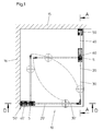
- FIG. 1 shows a plan view of a shower cubicle 10 with a first cabin wall 20 and a second cabin wall 20 '.
- the cabin walls 20, 20 ' are arranged at an angle to each other and define with two mutually spaced room walls 15, 16, z. B. building walls, the interior of the shower cubicle 10.
- a rectangular interior is formed.
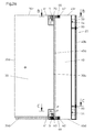
- the cabin wall 20 (see. FIGS. 2a to 4 ) has a door element 30 and a wall element 40 which are pivotally connected to each other about at least one fitting about a pivot axis S.
- a first fitting 60 is arranged in the lower region with the cabin wall 20, while a second fitting 70 is arranged in the upper region of the cabin wall 20.
- the door element 30 is formed substantially rectangular and has two mutually parallel longitudinal edges 30a, 30b and two mutually parallel transverse edges 30c, 30d. In the assembled state, the longitudinal edges 30a, 30b are substantially vertical, while the transverse edges 30c, 30d are substantially horizontal.
- the wall element 40 is also substantially rectangular with two mutually parallel longitudinal edges 40a, 40b and two mutually parallel transverse edges 40c, 40d formed.
- the longitudinal edges 40a, 40b are substantially vertical, while the transverse edges 40c, 40d are substantially horizontal.
- the longitudinal edge 40a in particular, faces the door element 30, while the longitudinal edge 40b on the side facing away from the door element 30 faces the corresponding room wall 15.
- the wall element 40 engages with its remote from the door member 30 longitudinal edge 40b in a wall rail 50 a.
- the wall rail 50 is formed as a U-profile and has two substantially parallel to each other aligned legs 51 and 52, which are interconnected by a profile base 53.
- the U-profile has a depth t, which is measured from the free end of the legs 51, 52 to the profile bottom 53.
- the U-profile in one of the legs 51, 52 for example in the leg 51 at least one in the present embodiment, two holes 54 which have an internal thread into which a screw 56 is screwed ( see. FIG. 4 ).
- the screws 56 are screwed into the bores 54, after the wall element 40 has been inserted with its longitudinal edge 40b ahead into the U-profile of the wall rail 50, the screws 56 can fix the wall element 40 between the respective screw 56 and the second leg 52 in a clamping manner.
- the depth t of the U-profile of the wall rail 50 is dimensioned such that the wall element 40 can be clamped in different depths inserted positions in the wall rail 50.
- the bore 54 is sufficiently far away from the profile base 53, for example by a distance a, which is at least 10 mm, advantageously at least 20 or even 30 mm.
- a fixation of the wall member 40 in the wall rail 50 is thus both possible when the wall element 40 is pushed into abutment against the bottom of the profile 53 in the U-profile, but also if the wall member 40 is about the distance a from this position from the U Profile of the wall rail 50 is pulled out.
- the wall element 40 can be fixed in the wall rail 50. This enables a variation of the distance between the profile base 53 and the longitudinal edge 40a of the wall element 40 facing the door element 30, and thus a variation and adjustment of the width of the cabin wall 20, in particular approximately at the distance a.
- the wall rail 50 is fixed to the room wall 15 in a manner described later in such a way that the profiled bottom 53 bears against the room wall 15, while the substantially vertically extending legs 51, 52 project at right angles from the room wall 15.
- a sealing element 57 for example in the form of a sealing cord, arranged to allow a seal against spray water.
- the sealing element 57 is preferably inserted in an inner groove 57 'of the respective limb 51 or 52 extending in the longitudinal direction of the limbs 51 and 52, respectively.
- the wall element 40 is fixed after installation in the wall rail 50 and rigidly fixed to the room wall 15.
- the door element 30 is pivotable by means of the fittings 60, 70 about the pivot axis S against the wall element 40.
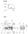
- the lower fitting 60 has a first fitting part 61 and a second fitting part 62.
- the first fitting part 61 is fixed to the door member 30 while the second fitting part 62 is fixed to the wall member 40.
- the first fitting part 61 has two cheek parts 61a and 61b, which bear against the two sides of the door element 30.
- a clamping screw 61c passes through the one cheek part 61b and a bore of the door element 30 and can be screwed into a threaded bore of the opposite cheek part 61a. By means of the clamping screw 61c, the cheek parts 61a and 61b can thus be pulled against each other in order to clamp the door element 30 located between the cheek parts 61a and 61b.
- the second fitting part 62 has two cheek parts 62a and 62b, which abut against the two sides of the wall member 40 and are fixed thereto.
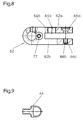
- the second fitting part 62 has first attachment means 63 and second attachment means 65.
- the two fastening means 62 and 65 are arranged side by side in the direction parallel to the transverse edge 40c, 40d.
- the first fastening means 63 has a screw 64c, which is screwed into a bore 64a arranged in the first cheek part 62a with an internal thread 64b.
- the wall element 40 arranged between the two cheek parts 62a, 62b is pressed by the screw 64c against the other cheek part 62b pressed and clamped between the screw 64c and the second cheek part 62b.
- the second fastening means 65 has a screw 66d which engages through a hole 66a provided in the first cheek part 62a and a recess arranged in the wall element 40 and is screwed into a bore 66b with an internal thread 66c arranged in the opposite cheek part 62b.
- the screw 66d clamps the two cheek parts 62a and 62b against each other in order to clamp the wall element 40 arranged between the cheek parts 62a, 62b in a clamping manner.
- the recess arranged in the wall element 40 is advantageously designed as a notch 46, which starts from the corresponding transverse edge 40c or 40d and, for example, leads approximately parallel to the respective longitudinal edge 40a into the wall element 40 (cf. FIG.
- the formation of the recess as a notch 46 has the advantage over training as a hole that with a wall element 40 made of glass, the notch 46 can be arranged close to the longitudinal edge 40a, without the risk of glass breakage.
- the second fitting part 62 can be made particularly compact, since in the direction parallel to the longitudinal edge 40a of the wall member 40 only a height of the fitting 62 is needed, which is sufficient to provide sufficient support surface for the heads of the screws 64c and 66d.
- the two juxtaposed fastening means 63 and 65 allow secure fixing of the wall element 40 in the fitting part 62 in the smallest space.
- the fitting parts 62 and 61 lie flush against the edges at the transverse edges 40d and 30d of the wall element 40 and the door element 30, respectively. As a result, a stable attachment of the fitting are combined with attractive minimal dimensions in an advantageous manner.
- the lower fitting 60 may include a raising and lowering mechanism 67, which is basically known in the art and serves to raise the door member 30 in a vertical direction when pivoted from a closed position to allow the door member 30 to pivot during pivotal movement does not touch the ground, but is lowered sealingly in the closed position towards the ground.
- a raising and lowering mechanism 67 which is basically known in the art and serves to raise the door member 30 in a vertical direction when pivoted from a closed position to allow the door member 30 to pivot during pivotal movement does not touch the ground, but is lowered sealingly in the closed position towards the ground.
- the upper fitting 70 is formed substantially corresponding to the lower fitting 60 and differs from the fitting 60 in that instead of the raising and lowering mechanism 67, a bearing pin 77 is provided, around which the pivotal movement of the door member 30 takes place.
- the fittings of the upper fitting 70 are flush with the edge at the upper transverse edges 30c and 40c of the door member 30 and the wall member 40 at.
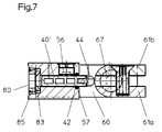
- the Figures 5 . 6 and 7 show the Figures 2 . 3 and 4 corresponding views of the second cabin wall 20 '.
- Like reference numerals designate like parts.
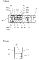
- the wall rail 50 ' In order to arrange the door member 30 so close to the wall rail 50 ', on the other hand, however, the second fitting part 62 to be securely fastened to the wall member 40', the wall rail 50 'at its upper and lower end recesses 58', which for receiving a portion of the second fitting part 62 serve (see. FIG. 6b ).
- the recesses 58 ' are formed in that only the legs 51 and 52 of the U-profile with a reduced wall thickness remain, while the profile base 53 is removed and the clear width between the legs 51 and 52 is expanded by reducing material on the inside of these legs 51 and 52.
- the second fitting parts 62 of the upper fitting 60 and the lower fitting 70 can be inserted so far into the corresponding upper and lower recesses 58 'that substantially only the portions of these fittings 62 with the pivot axis S outside of the legs 51 and 52 of the wall rail 50 ', as in FIG. 6a you can see.
- the wall element 40 ', which is clamped in the lower and upper second fitting parts 62, is formed in this embodiment as a narrow rail, which is almost completely taken up in the tread depth t of the wall rail 50'.
- the door member 30 with the pivot axis S can be mounted so close to the wall rail 50 ', that at a distance no difference results to a shower cubicle, in which the door element is mounted by means of fittings directly to the room wall.
- the design of the fittings 60 and 70 and the attachment of the wall rail 50 ' is identical, regardless of whether a wall element 40 of greater width or a narrow wall element 40' is used.
- the wall element 40' advantageously has, in its end edge facing the door element 30, a vertically continuous groove 42 into which a seal 44 (FIG. FIG. 9 ) is used.
- the seal 44 has a groove 42 adapted to the web, which may have, for example, ribs for better fixation in the groove 42, and a subsequent to the web rounded mushroom-shaped head, which covers the door element 30 facing end face of the wall member 40 '.
- the mushroom-shaped head is advantageously flexible, e.g. B. hollow, in order to pivot the door element 30 opposite the wall element 40 'to the changing distance between the door element 30 facing the longitudinal edge 40a of the wall element 40' and the wall element 40 'facing longitudinal edge 30b of the door member 30 account.
- the door element 30 is preferably made of glass or plastic and advantageously transparent.
- the wall element 40 is preferably made in accordance with the door member 30 made of glass or a transparent plastic. If a wall element 40 'of small width is provided, which is almost completely received in the wall rail 50', then the wall element 40 'can preferably also be made of metal in view of the higher stability.
- the wall element 40 ' is an aluminum profile with internal cavities, as the FIGS. 6a and 7 demonstrate. This design combines high stability with low weight and material requirements.
- the wall rail 50 has a U-profile with two legs 51 and 52 and a profile base connecting these legs 53. In one of the legs 52, the holes 54 are formed, in which the screws 56 are screwed for clamping the wall member 40/40 '.
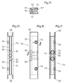
- the profiled bottom 53 of the wall rail 50 has at least two openings 80 spaced apart in the longitudinal direction.
- the apertures 80 are arranged centrally in the profile base 53.
- the clear inner width between the legs 51 and 52 in the form of a coaxial with the opening 80 cylinder 81 is then widened to the opening 80.
- the opening 80 has a diameter which is greater than the diameter of the cylinder 81 and consequently larger than the clear inner width between the legs 51 and 52.
- the opening 80 forms a circular disc-shaped receiving space 82, the after the outside of the profile base 53 is open towards and is limited to the inside by the legs 51 and 52, as in the FIGS. 11 and 12 can be seen.
- the receiving space 82 is formed with an internal thread.
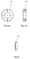
- an adjusting disc 83 is inserted, which as a single part in FIG. 15 is shown in axial section.
- the adjusting disk 83 has the shape of a circular disk whose outer diameter is smaller than the inner diameter of the receiving space 82, but larger than the inner diameter of the cylinder 81.
- the inner diameter of the adjusting disc 83 corresponds to the diameter of the screws 84, with which the wall rail 50 on the respective room wall 15 is attached.
- the thickness of the adjusting disc 83 is smaller than the thickness of the profile base 53.
- a cover screw 85 is screwed, which has the shape of a circular disk whose external thread corresponds to the internal thread of the receiving space 82.
- the inner diameter of the cover screw 85 is greater than the inner diameter of the adjusting disk 83, but smaller than the outer diameter of the adjusting disk 83.
- the thickness of the cover screw 85 is less than the thickness of the profile base 53.
- the adjusting disk 83 is inserted into the receiving space 82 and then the cover screw 85, so the adjusting disc 83 is held in the receiving space 82, but in this case due to its relative to the inner diameter of the receiving space 82 smaller outer diameter radially displaceable.
- the mounting of the wall rail 50, 50 ' can be carried out in a simple manner by a single person in the following manner.
- the position of the wall rails 50, 50 ' is determined.
- the wall rails 50, 50 ' are mounted vertically aligned in this position on the respective room wall 15, 16, for which purpose preferably serve on the voltage applied to the room wall 15, 16 outside of the profile base 53 adhesive pads.
- After this provisional fixation of the wall rails 50, 50 'guide bushes 86 are inserted into the respective expanded cylinder 81.
- the guide bushes 86 which may be made of plastic, for example, have a cylindrical shape whose outer diameter corresponds to the inner diameter of the Zyinder 81, so that the guide bushes 86 can be used without play in the flared cylinder 81.
- the guide bushing 86 is held against rotation in the cylinder 81.
- the inner diameter of the guide bushes 86 corresponds to the diameter of a drill 87, which in FIG. 15 is shown in the beginning.
- the drill 87 can now be performed by the guide bush 86 axially precisely guided through the opening 80, the adjusting disc 83 and the cover screw 85 in the room wall 15 and 16, there to pre-drill a suitable hole.
- the pre-drilled holes can now be extended using a larger diameter drill to insert dowels into these holes.
- the guide bushes 86 are now removed from the wall rails 50, 50 'and the wall rails 50, 50' are again positioned on the respective room wall 15, 16. Now, the screws 84 are inserted and through the Adjusting washer 83 screwed into the respective dowel.
- the diameter of the screws 84 corresponds to the inner diameter of the adjusting disc 83, while the diameter of the screw head corresponds to the inner diameter of the expanded cylinder 81.
- the screw 84 can thus be inserted through the cylinder 81, fits with its screw head in the conical inner diameter of the adjusting washer 83, whereby the adjusting disk 83 via the cover screw 85, the wall rail 50, 50 'against when screwing the screw 84 into the dowel the room wall 15, 16 braced and fixed.
- the screw 84 Before tightening the screw 84 is a readjustment of the exact position of the wall rail 50, 50 'possible because the adjusting disc 83 is displaceable with the screw 84 in the receiving space 82 with radial play, so that the wall rail 50, 50' relative to the screw 84 is slightly displaceable.
- the installation of the wall rail 50, 50 ' has the advantage that this assembly can be performed by an individual without additional aids simple and accurate.
- the arrangement of the screws 84 in the profile base 53 of the wall rails 50, 50 ' is invisible after mounting the wall rail 50, 50', so that a shapely appearance of the wall rail results in high stability, without broadening the wall rail is necessary.
- the screws 84 inserted and screwed in are covered by the wall elements 40, 40 'subsequently inserted into the wall rails 50, 50'.
Abstract
Wandschiene zur Befestigung eines feststehenden Wandelements (40, 40') einer Duschkabine (10) an einer Raumwand (15, 16), wobei die Wandschiene (50, 50') ein U-Profil aufweist, zwischen dessen Schenkeln (51, 52) das Wandelement (40, 40') einsetzbar und klemmbar ist, und wobei die Wandschiene (50, 50') mittels Schrauben (84) an der Raumwand (15, 16) befestigbar ist, wobei das U-Profil in dem an der Raumwand (15, 16) zur Anlage kommenden Profilgrund (53) mittig im Profilquerschnitt wenigstens zwei durchgehende Bohrungen für die Schrauben (84) aufweist und dass die lichte Weite des U-Profils zwischen den Schenkeln (51, 52) als zu der jeweiligen Bohrung koaxialer Zylinder (81) aufgeweitet ist.

Description
Die Erfindung betrifft eine Wandschiene zur Befestigung eines feststehenden Wandelements einer Duschkabine gemäß dem Oberbegriff des Patentanspruchs 1.The invention relates to a wall rail for fastening a fixed wall element of a shower cubicle according to the preamble of patent claim 1.
Duschkabinen weisen häufig ein feststehendes Wandelement auf, welches an einer Raumwand, z. B. eines Badezimmers montiert wird. An dem feststehenden Wandelement kann schwenkbar ein Türelement angebracht werden. Ebenso ist es möglich, ein schwenkbares Türelement so anzuordnen, dass dieses in der Schließstellung der Duschkabine an dem feststehenden Wandelement zur Anlage kommt.Shower cubicles often have a fixed wall element, which on a room wall, for. B. a bathroom is mounted. On the fixed wall element, a door element can be pivotally mounted. It is also possible to arrange a pivotable door element so that it comes to rest in the closed position of the shower cubicle on the fixed wall element.
Um das feststehende Wandelement an der Raumwand zu befestigen, ist es bekannt, an der Raumwand eine Wandschiene anzubringen, vorzugsweise mittels Schrauben an der Raumwand anzuschrauben. Die Wandschiene dient zur Aufnahme des feststehenden Wandelements. Hierzu kann die Wandschiene ein U-Profil aufweisen, zwischen dessen Schenkeln das Wandelement einsetzbar und klemmbar ist. Wandschienen dieser Gattung sind beispielsweise in der
Bei diesen bekannten Wandschienen ist zur Befestigung des U-Profils an der Raumwand ein seitlich über das U-Profil hinausragender Schenkel vorgesehen, der die Bohrungen zur Aufnahme der Befestigungsschrauben aufweist. Die seitlich neben dem U-Profil angeordnete Befestigung der Wandschiene beeinträchtigt das formschöne Design und macht gegebenenfalls eine zusätzliche Abdeckung notwendig. Außerdem ist die Montage der bekannten Wandschienen schwierig, da in der Regel zwei Personen benötigt werden, um einerseits die Wandschiene zu positionieren und positioniert zu halten und andererseits die Schraubbefestigung vorzunehmen.In these known wall rails, a laterally projecting beyond the U-profile leg is provided for fastening the U-profile on the room wall, which has the holes for receiving the fastening screws. The laterally arranged next to the U-profile fastening of the wall rail affects the shapely design and makes possibly an additional cover necessary. In addition, the installation of the known wall rails is difficult, since usually two people are needed to position one hand, the wall rail and positioned to hold and on the other hand make the screw fastening.
Der Erfindung liegt die Aufgabe zugrunde, eine Wandschiene für ein feststehendes Wandelement einer Duschkabine zur Verfügung zu stellen, welche ein formschönes Aussehen und eine einfache Montagemöglichkeit ermöglicht.The invention has for its object to provide a wall rail for a fixed wall element of a shower cubicle available, which allows a shapely appearance and easy mounting option.
Diese Aufgabe wird erfindungsgemäß gelöst durch eine Wandschiene mit den Merkmalen des Patentanspruchs 1.This object is achieved by a wall rail with the features of claim 1.
Vorteilhafte Ausführungen der Erfindung sind in den Unteransprüchen angegeben.Advantageous embodiments of the invention are specified in the subclaims.
Die erfindungsgemäße Wandschiene weist ein U-Profil auf, wobei die Befestigung an der Raumwand durch Schrauben bewirkt wird, die in dem Profilgrund des U-Profils angeordnet sind. Dadurch ist die Schraubbefestigung der Wandschiene nicht von außen sichtbar, wenn die Wandschiene montiert ist. Die Schrauben zur Befestigung der Wandschiene werden nach dem Einsetzen des Wandelements in das U-Profil durch dieses Wandelement abgedeckt. Nach der Montage der Duschkabine ist von der Befestigung des Wandelements an der Raumwand sowohl von der Außenseite als auch von der Innenseite der Duschkabine lediglich die durchgehend glatte Außenfläche der Schenkel des U-Profils zu sehen. Dadurch ergibt sich ein formschönes gefälliges Aussehen der Wandbefestigung und damit der gesamten Duschkabine.The wall rail according to the invention has a U-profile, wherein the attachment to the room wall is effected by screws, which are arranged in the profile base of the U-profile. As a result, the screw fastening the wall rail is not visible from the outside when the wall rail is mounted. The screws for fixing the wall rail are covered after insertion of the wall element in the U-profile by this wall element. After installation of the shower cubicle, only the continuous smooth outer surface of the legs of the U-profile can be seen from the attachment of the wall element to the room wall, both from the outside and from the inside of the shower cubicle. This results in a shapely pleasing appearance of the wall mounting and thus the entire shower cubicle.
Um eine hohe Stabilität sowohl der Befestigung der Wandschiene an der Raumwand als auch der Befestigung des Wandelements in der Wand zu gewährleisten ist die innere lichte Breite des U-Profils zwischen den Schenkeln in Form eines inneren hohlen Zylinders aufgeweitet, der senkrecht zum Profilgrund koaxial zu der jeweiligen Bohrung für die zur Befestigung dienende Schraube verläuft. Diese zylindrische Aufweitung bietet den Vorteil, dass die lichte Weite des U-Profils zwischen den Schenkeln im übrigen so minimal gehalten werden kann, wie es zur Aufnahme des Wandelements notwendig ist. Durch die zylindrische Aufweitung kann eine stabile Befestigungsschraube eingesetzt werden, deren Schraubenkopf einen Durchmesser aufweist, der größer ist als die lichte Weite des U-Profils und dem Innendurchmesser des aufgeweiteten Zylinders entspricht. Dies ergibt eine hohe Stabilität der Befestigung der Wandschiene an der Raumwand, ohne dass dadurch die Dicke der Schenkel U-Profils vergrößert werden muss. Die Dicke der Schenkel des U-Profils wird daher nur durch die Materialstärke bestimmt, die zu einer stabilen Halterung des Wandelements erforderlich ist. Dies ermöglicht eine besonders schlanke und elegante Ausführung der Wandschiene.In order to ensure a high stability of both the attachment of the wall rail to the room wall and the attachment of the wall element in the wall, the inner clear width of the U-profile between the legs in the form of an inner hollow cylinder is widened, which is perpendicular to the profile base coaxial to the respective hole for the fastening screw serving runs. This cylindrical expansion offers the advantage that the clear width of the U-profile between the legs can otherwise be kept as minimal as it is necessary to accommodate the wall element. Through the cylindrical expansion, a stable fastening screw can be used, the screw head has a diameter which is greater than the clear width of the U-profile and the inner diameter of the flared cylinder corresponds. This results in a high stability of the attachment of the wall rail to the room wall, without thereby the thickness of the leg U-profile must be increased. The thickness of the legs of the U-profile is therefore determined only by the material thickness, which is required for a stable mounting of the wall element. This allows a particularly slim and elegant design of the wall rail.
Die Montage der Wandschiene ist besonders einfach und kann insbesondere auch von einer Einzelperson durchgeführt werden. Die Wandschiene wird hierzu in der ausgerichteten Position mittels einer provisorischen Klebung an der Raumwand befestigt. In die zylindrische Aufweitung der Schenkel des U-Profils kann eine Führungsbuchse eingesetzt werden, durch welche präzise geführt ein dünner Bohrer eingeführt werden kann, um ein jeweiliges Bohrloch in der Raumwand zu markieren. Die provisorisch fixierte Wandschiene wird dann abgenommen und die vormarkierten Bohrlöcher werden zum Einsetzen von Wanddübeln vergrößert. Nach dem Einsetzen der Dübel wird die Wandschiene wieder in Position gebracht und nach Entfernen der Führungsbuchsen können die Schrauben durch den aufgeweiteten Zylinderraum eingesetzt und in die Dübel eingedreht werden.The mounting of the wall rail is particularly simple and can be carried out in particular by an individual. For this purpose, the wall rail is fastened to the room wall in the aligned position by means of a provisional bond. In the cylindrical expansion of the legs of the U-profile, a guide bush can be used, through which precisely guided a thin drill can be inserted to mark a respective hole in the room wall. The provisionally fixed wall rail is then removed and the pre-marked holes are enlarged for insertion of wall plugs. After inserting the dowels, the wall rail is brought back into position and after removing the guide bushes, the screws can be inserted through the widened cylinder chamber and screwed into the dowels.
In einer bevorzugten Ausführung sind in dem Profilgrund der Wandschiene Justierscheiben angeordnet, in welche die zur Befestigung dienenden Schrauben eingesetzt werden. Die Justierschrauben sind in geringem Maße in der Ebene des Profilgrundes verschiebbar. Dadurch ist ein geringes Verschieben der Wandschiene gegenüber den in die Wanddübel eingesetzten Schrauben möglich, um eine feine Nachjustierung der Position der Wandschienen zu ermöglichen, bevor die Schrauben fest angezogen werden und die Wandschiene über die Justierscheibe an der Raumwand verspannen und fixieren.In a preferred embodiment, alignment plates are arranged in the profile base of the wall rail, in which the serving for fastening screws are used. The adjusting screws are displaced to a slight extent in the plane of the profile ground. As a result, a small displacement of the wall rail relative to the screws used in the wall plugs is possible to allow a fine readjustment of the position of the wall rails before the screws are tightened and brace the wall rail on the adjusting plate on the room wall and fix.
Das Wandelement wird in das U-Profil der Wandschiene eingesetzt und mittels Schrauben in der Wandschiene geklemmt und fixiert. Dadurch ist es möglich, das Wandelement in seiner Ebene im Abstand von der Raumwand zu justieren. Hierzu kann die in die Wandschiene aufgenommene Kante des Wandelements unterschiedlich tief in das U-Profil der Wandschiene eingeschoben werden, bevor das Wandelement in der Wandschiene geklemmt und fixiert wird.The wall element is inserted into the U-profile of the wall rail and clamped and fixed by means of screws in the wall rail. This makes it possible to adjust the wall element in its plane at a distance from the room wall. For this purpose, the recorded in the wall rail edge of the wall element can be inserted at different depths in the U-profile of the wall rail before the wall element is clamped and fixed in the wall rail.
Im Folgenden wird die Erfindung anhand eines in der Zeichnung dargestellten Ausführungsbeispiels näher erläutert. Es zeigen:
- Figur 1 :
- einen Horizontalschnitt durch ein Ausführungsbeispiels einer Duschkabine,
- Figur 2a:
- einen Vertikalschnitt durch eine Kabinenwand der Duschkabine gemäß der Schnittlinie A-A in
Figur 1 , - Figur 2b:
- einen Ausschnitt aus dem Wandelement der Kabinenwand,
- Figur 3:
- einen horizontalen Teilschnitt gemäß der Schnittlinie B-B in
Figur 2a , - Figur 4:
- einen horizontalen Teilschnitt gemäß der Schnittlinie C-C in
Figur 2a , - Figur 5:
- einen Vertikalschnitt durch die zweite Kabinenwand gemäß der Schnittlinie D-D in
Figur 1 , - Figur 6a:
- einen horizontalen Teilschnitt gemäß der Schnittlinie E-E in
Figur 5 , - Figur 6b:
- eine Teilansicht auf das Ende der Wandschiene gemäß
Figur 6a , - Figur 7:
- einen horizontalen Teilschnitt durch die zweite Kabinenwand gemäß der Schnittlinie F-F in
Figur 5 , - Figur 8:
- eine Detaildarstellung des zweiten Beschlagteiles des Beschlags der Kabinenwand gemäß den
Figuren 2a oder5 , - Figur 9:
- eine Draufsicht auf die Dichtung des Wandelements gemäß
Figur 5 , - Figur 10:
- eine Seitenansicht der Wandschiene der Duschkabine,
- Figur 11:
- eine Frontansicht der Wandschiene von der an der Raumwand anliegenden Seite,
- Figur 12:
- eine Frontansicht der Wandschiene von der von der Raumwand abgewandten Seite,
- Figur 13:
- einen Querschnitt durch die Wandschiene gemäß der Schnittlinie G-G in
Figur 10 - Figur 14a und Figur 14b:
- eine Draufsicht und einen Axialschnitt einer Deckschraube,
- Figur 15:
- einen Axialschnitt einer Justierscheibe und
- Figur 16:
- eine Explosionsdarstellung der Wandschiene und ihrer Befestigungsmittel.
- FIG. 1:
- a horizontal section through an embodiment of a shower cubicle,
- FIG. 2a:
- a vertical section through a cabin wall of the shower cubicle according to the section line AA in
FIG. 1 . - FIG. 2b:
- a section of the wall element of the cabin wall,
- FIG. 3:
- a horizontal partial section along the section line BB in
FIG. 2a . - FIG. 4:
- a horizontal partial section along the section line CC in
FIG. 2a . - FIG. 5:
- a vertical section through the second cabin wall according to the section line DD in
FIG. 1 . - FIG. 6a:
- a horizontal partial section according to the section line EE in
FIG. 5 . - FIG. 6b:
- a partial view of the end of the wall rail according to
FIG. 6a . - FIG. 7:
- a horizontal partial section through the second cabin wall according to the section line FF in
FIG. 5 . - FIG. 8:
- a detailed representation of the second fitting part of the fitting of the cabin wall according to the
FIGS. 2a or5 . - FIG. 9:
- a plan view of the seal of the wall element according to
FIG. 5 . - FIG. 10:
- a side view of the wall rail of the shower cubicle,
- FIG. 11:
- a front view of the wall rail from the side adjacent to the room wall,
- FIG. 12:
- a front view of the wall rail from the side facing away from the room wall,
- FIG. 13:
- a cross section through the wall rail according to the section line GG in
FIG. 10 . - FIGS. 14a and 14b:
- a top view and an axial section of a cover screw,
- FIG. 15:
- an axial section of an adjusting and
- FIG. 16:
- an exploded view of the wall rail and its fastening means.
Die Kabinenwand 20 (vgl.
Das Türelement 30 ist im Wesentlichen rechteckig ausgebildet und weist zwei parallel zueinander verlaufende Längskanten 30a, 30b und zwei parallel zueinander verlaufende Querkanten 30c, 30d auf. Im montierten Zustand verlaufen die Längskanten 30a, 30b im Wesentlichen vertikal, während die Querkanten 30c, 30d im Wesentlichen horizontal verlaufen.The
Das Wandelement 40 ist ebenfalls im Wesentlichen rechteckig mit zwei parallel zueinander angeordneten Längskanten 40a, 40b und zwei parallel zueinander angeordneten Querkanten 40c, 40d ausgebildet. Im montierten Zustand verlaufen die Längskanten 40a, 40b im Wesentlichen vertikal, während die Querkanten 40c, 40d im Wesentlichen horizontal verlaufen. Die Längskante 40a ist insbesondere dem Türelement 30 zugewandt, während die Längskante 40b auf der dem Türelement 30 abgewandten Seite der entsprechenden Raumwand 15 zugewandt ist.The
Das Wandelement 40 greift mit seiner von dem Türelement 30 abgewandten Längskante 40b in eine Wandschiene 50 ein. Die Wandschiene 50 ist als U-Profil ausgebildet und weist zwei im Wesentlichen parallel zueinander ausgerichtete Schenkel 51 und 52 auf, welche durch einen Profilgrund 53 miteinander verbunden sind. Das U-Profil weist eine Tiefe t auf, welche vom freien Ende der Schenkel 51, 52 bis zu dem Profilgrund 53 gemessen ist.The
Zur Befestigung des Wandelements 40 in der Wandschiene 50 weist deren U-Profil in einem der Schenkel 51, 52, beispielsweise in dem Schenkel 51 wenigstens eine im vorliegenden Ausführungsbeispiel zwei Bohrungen 54 auf, welche eine Innengewinde aufweisen, in welches eine Schraube 56 eindrehbar ist (vgl.
Werden die Schrauben 56 in die Bohrungen 54 eingedreht, nachdem das Wandelement 40 mit seiner Längskante 40b voran in das U-Profil der Wandschiene 50 eingeschoben wurde, können die Schrauben 56 das Wandelement 40 zwischen der jeweiligen Schraube 56 und dem zweiten Schenkel 52 klemmend fixieren.If the
Die Tiefe t des U-Profils der Wandschiene 50 ist dabei derart bemessen, dass das Wandelement 40 in verschieden tief eingeschobenen Positionen in der Wandschiene 50 klemmbar ist. Dazu ist die Bohrung 54 ausreichend weit vom Profilgrund 53 entfernt, beispielsweise um einen Abstand a, welcher mindestens 10 mm, vorteilhafterweise mindestens 20 oder sogar 30 mm beträgt. Eine Fixierung des Wandelements 40 in der Wandschiene 50 ist damit sowohl möglich, wenn das Wandelement 40 bis auf Stoß gegen den Profilgrund 53 in das U-Profil hineingeschoben ist, aber auch wenn das Wandelement 40 etwa um den Abstand a aus dieser Position aus dem U-Profil der Wandschiene 50 herausgezogen ist. Auch in sämtlichen Zwischenpositionen ist selbstverständlich das Wandelement 40 in der Wandschiene 50 fixierbar. Dies ermöglicht eine Variation des Abstandes zwischen dem Profilgrund 53 und der dem Türelement 30 zugewandten Längskante 40a des Wandelements 40 und somit eine Variation und Justage der Breite der Kabinenwand 20, insbesondere etwa maximal um den Abstand a.The depth t of the U-profile of the
Die Wandschiene 50 wird in später beschriebener Weise derart an der Raumwand 15 fixiert, dass der Profilgrund 53 an der Raumwand 15 anliegt, während die im Wesentlichen vertikal verlaufenden Schenkel 51, 52 rechtwinklig von der Raumwand 15 abstehen.The
Zwischen wenigstens einem der Schenkel 51, 52 und dem Wandelement 40, vorteilhafterweise zwischen beiden Schenkeln 51 und 52 und dem Wandelement 40 ist ein Dichtelement 57, beispielsweise in Form einer Dichtschnur, angeordnet, um eine Abdichtung gegen Spritzwasser zu ermöglichen. Das Dichtelement 57 ist vorzugsweise in einer in Längsrichtung der Schenkel 51 bzw. 52 verlaufenden Innennut 57' des jeweiligen Schenkels 51 bzw. 52 eingelegt.Between at least one of the
Das Wandelement 40 ist nach der Montage in der Wandschiene 50 feststehend und starr an der Raumwand 15 fixiert. Das Türelement 30 ist mittels der Beschläge 60, 70 um die Schwenkachse S gegen das Wandelement 40 schwenkbar.The
Der untere Beschlag 60 weist ein erstes Beschlagteil 61 und ein zweites Beschlagteil 62 auf. Das erste Beschlagteil 61 ist an dem Türelement 30 befestigt, während das zweite Beschlagteil 62 an dem Wandelement 40 befestigt ist. Das erste Beschlagteil 61 weist zwei Wangenteile 61a und 61b auf, welche an den beiden Seiten des Türelements 30 anliegen. Eine Klemmschraube 61c durchsetzt das eine Wangenteil 61b und eine Bohrung des Türelements 30 und ist in eine Gewindebohrung des gegenüberliegenden Wangenteils 61a einschraubbar. Mittels der Klemmschraube 61c können somit die Wangenteile 61a und 61b gegeneinander gezogen werden, um das zwischen den Wangenteilen 61a und 61b liegende Türelement 30 klemmend zu halten.The
Das zweite Beschlagteil 62 weist zwei Wangenteile 62a und 62b auf, welche an den beiden Seiten des Wandelements 40 anliegen und an diesem fixiert sind. In dem dargestellten Ausführungsbeispiel weist das zweite Beschlagteil 62 erste Befestigungsmittel 63 und zweite Befestigungsmittel 65 auf. Die beiden Befestigungsmittel 62 und 65 sind in Richtung parallel zur Querkante 40c, 40d nebeneinander angeordnet.The second
Das erste Befestigungsmittel 63 weist eine Schraube 64c auf, welche in eine in dem ersten Wangenteil 62a angeordnete Bohrung 64a mit einem Innengewinde 64b eingedreht wird. Das zwischen den beiden Wangenteilen 62a, 62b angeordnete Wandelement 40 wird durch die Schraube 64c gegen das andere Wangenteil 62b gedrückt und zwischen der Schraube 64c und dem zweiten Wangenteil 62b klemmend fixiert.The first fastening means 63 has a screw 64c, which is screwed into a
Das zweite Befestigungsmittel 65 weist eine Schraube 66d auf, welche durch eine in dem ersten Wangenteil 62a vorgesehene Bohrung 66a sowie eine in dem Wandelement 40 angeordnete Ausnehmung hindurchgreift und in ein in dem gegenüberliegenden Wangenteil 62b angeordnete Bohrung 66b mit einem Innengewinde 66c eingedreht wird. Dadurch verspannt die Schraube 66d die beiden Wangenteile 62a und 62b gegeneinander, um das zwischen den Wangenteilen 62a, 62b angeordnete Wandelement 40 klemmend zu fixieren. Die in dem Wandelement 40 angeordnete Ausnehmung ist vorteilhafterweise als Kerbe 46 ausgebildet, welche von der entsprechenden Querkante 40c bzw. 40d ausgeht und beispielsweise etwa parallel zur jeweiligen Längskante 40a in das Wandelement 40 hineinführt (vgl.
Der untere Beschlag 60 kann einen Hebe-Senk-Mechanismus 67 aufweisen, welcher grundsätzlich aus dem Stand der Technik bekannt ist und dazu dient, dass das Türelement 30 bei Verschwenken aus einer geschlossenen Position in vertikaler Richtung angehoben wird, damit das Türelement 30 bei der Verschwenkbewegung nicht über den Boden streift, jedoch in der geschlossenen Position zum Boden hin abdichtend abgesenkt wird.The
Der obere Beschlag 70 ist im Wesentlichen entsprechend dem unteren Beschlag 60 ausgebildet und unterscheidet sich von dem Beschlag 60 darin, dass statt des Hebe-Senk-Mechanismus 67 ein Lagerbolzen 77 vorgesehen ist, um welchen die Schwenkbewegung des Türelements 30 erfolgt. Auch die Beschlagteile des oberen Beschlages 70 liegen kantenbündig an den oberen Querkanten 30c bzw. 40c des Türelements 30 bzw. des Wandelements 40 an.The
Die
Um das Türelement 30 derart dicht an der Wandschiene 50' anordnen zu können, andererseits jedoch das zweite Beschlagteil 62 sicher an dem Wandelement 40' befestigen zu können, weist die Wandschiene 50' an ihrem oberen und unteren Ende Ausnehmungen 58' auf, welche zur Aufnahme eines Abschnitts des zweiten Beschlagteils 62 dienen (vgl.
Um das Türelement 30 gegen das Wandelement 40' abdichten zu können, weist vorteilhafterweise das Wandelement 40' in seiner dem Türelement 30 zugewandten Stirnkante eine vertikal durchgehende Nut 42 auf, in welche eine Dichtung 44 (
Das Türelement 30 ist vorzugsweise aus Glas oder Kunststoff gefertigt und vorteilhafterweise transparent. Das Wandelement 40 ist vorzugsweise übereinstimmend mit dem Türelement 30 aus Glas oder einem transparentem Kunststoff hergestellt. Ist ein Wandelement 40' geringer Breite vorgesehen, welches nahezu vollständig in der Wandschiene 50' aufgenommen ist, so kann das Wandelement 40' vorzugsweise im Hinblick auf die höhere Stabilität auch aus Metall gefertigt sein. Zweckmäßig ist in dieser Ausführung das Wandelement 40' ein Aluminiumprofil mit Innenhohlräumen, wie dies die
Anhand der
Die Wandschiene 50 weist ein U-Profil auf mit zwei Schenkeln 51 und 52 und einem diese Schenkel verbindenden Profilgrund 53. In einem der Schenkel 52 sind die Bohrungen 54 ausgebildet, in welche die Schrauben 56 zum Klemmen des Wandelements 40/40' eingedreht werden. Zur Befestigung der Wandschiene 50, 50' an der jeweiligen Raumwand 15, 16 weist der Profilgrund 53 der Wandschiene 50 wenigstens zwei in Längsrichtung beabstandete Durchbrüche 80 auf. Die Durchbrüche 80 sind mittig in dem Profilgrund 53 angeordnet. Im Inneren des U-Profils der Wandschiene 50 ist anschließend an den Durchbruch 80 die lichte innere Weite zwischen den Schenkeln 51 und 52 in Form eines zu dem Durchbruch 80 koaxialen Zylinder 81 aufgeweitet. Innerhalb der Dicke des Profilgrundes 53 weist der Durchbruch 80 einen Durchmesser auf, der größer ist als der Durchmesser des Zylinders 81 und demzufolge auch größer als die lichte innere Weite zwischen den Schenkeln 51 und 52. Dadurch bildet der Durchbruch 80 einen kreisscheibenförmigen Aufnahmeraum 82, der nach der Außenseite des Profilgrundes 53 hin offen ist und nach der Innenseite hin durch die Schenkel 51 und 52 begrenzt ist, wie in den
Die Montage der Wandschiene 50, 50' kann in einfacher Weise durch eine einzelne Person in folgender Weise durchgeführt werden.The mounting of the
Mit einer die Grundrissabmessungen der Duschkabine 10 darstellenden Schablone wird die Position der Wandschienen 50, 50' festgelegt. Die Wandschienen 50, 50' werden in dieser Position vertikal ausgerichtet an der jeweiligen Raumwand 15, 16 angebracht, wozu vorzugsweise an der an der Raumwand 15, 16 anliegenden Außenseite des Profilgrundes 53 angebrachte Klebepads dienen. Nach dieser provisorischen Fixierung der Wandschienen 50, 50' werden Führungsbuchsen 86 in die jeweiligen aufgeweiteten Zylinder 81 eingesetzt. Die Führungsbuchsen 86, die beispielsweise aus Kunststoff bestehen können, haben eine zylindrische Form, deren Außendurchmesser dem Innendurchmesser der Zyinder 81 entspricht, so dass die Führungsbuchsen 86 spielfrei in die aufgeweiteten Zylinder 81 eingesetzt werden können. Vorzugsweise wird die Führungsbuchse 86 verdrehsicher in dem Zylinder 81 gehalten. Der Innendurchmesser der Führungsbuchsen 86 entspricht dem Durchmesser eines Bohrers 87, der in
Die Montage der Wandschiene 50, 50' hat den Vorteil, dass diese Montage von einer Einzelperson ohne zusätzliche Hilfsmittel einfach und präzise durchgeführt werden kann. Die Anordnung der Schrauben 84 im Profilgrund 53 der Wandschienen 50, 50' ist nach Montage der Wandschiene 50, 50' unsichtbar, so dass sich ein formschönes Aussehen der Wandschiene mit hoher Stabilität ergibt, ohne dass eine Verbreiterung der Wandschiene notwendig ist. Die eingesetzten und eingeschraubten Schrauben 84 werden durch die anschließend in die Wandschienen 50, 50' eingesetzten Wandelemente 40, 40' abgedeckt.The installation of the
- 1010
- Duschkabineshower cabin
- 1515
- Raumwandroom wall
- 1616
- Raumwandroom wall
- 2020
- Kabinenwandcabin wall
- 20'20 '
- Kabinenwandcabin wall
- 3030
- Türelementdoor element
- 30a30a
- Längskantelongitudinal edge
- 30b30b
- Längskantelongitudinal edge
- 30c30c
- Querkantetransverse edge
- 30d30d
- Querkantetransverse edge
- 4040
- Wandelementwall element
- 40'40 '
- Wandelementwall element
- 40a40a
- Längskantelongitudinal edge
- 40b40b
- Längskantelongitudinal edge
- 40c40c
- Querkantetransverse edge
- 40d40d
- Querkantetransverse edge
- 4242
- Nutgroove
- 4444
- Dichtungpoetry
- 4646
- Kerbescore
- 5050
- Wandschienewall rail
- 50'50 '
- Wandschienewall rail
- 5151
- Schenkelleg
- 5252
- Schenkelleg
- 5353
- Profilgrundprofile base
- 5454
- Bohrungdrilling
- 5656
- Schraubescrew
- 5757
- Dichtelementsealing element
- 57'57 '
- Innennutinner groove
- 58'58 '
- Ausnehmungrecess
- 6060
- Beschlagfitting
- 6161
- Erstes BeschlagteilFirst fitting part
- 61a61a
- Wangenteilstring part
- 61b61b
- Wangenteilstring part
- 61c61c
- Klemmschraubeclamping screw
- 6262
- Zweites BeschlagteilSecond fitting part
- 62a62a
- Wangenteilstring part
- 62b62b
- Wangenteilstring part
- 6363
- Erstes BefestigungsmittelFirst fastener
- 64a64a
- Bohrungdrilling
- 64b64b
- Innengewindeinner thread
- 64c64c
- Schraubescrew
- 6565
- Zweites BefestigungsmittelSecond fastening means
- 66a66a
- Bohrungdrilling
- 66b66b
- Bohrungdrilling
- 66c66c
- Innengewindeinner thread
- 66d66d
- Schraubescrew
- 6767
- Hebe-Senk-MechanismusLifting and lowering mechanism
- 7070
- Beschlagfitting
- 7777
- Lagerbolzenbearing bolt
- 8080
- Durchbrüchebreakthroughs
- 8181
- Zylindercylinder
- 8282
- Aufnahmeraumaccommodation space
- 8383
- Justierscheibeadjustment disc
- 8484
- Schraubescrew
- 8585
- Deckschraubecover screw
- 8686
- Führungsbuchseguide bush
- 8787
- Bohrerdrill
- tt
- Profiltiefetread depth
- aa
- Abstanddistance
- SS
- Schwenkachseswivel axis
Claims (8)
dadurch gekennzeichnet, dass das U-Profil in dem an der Raumwand (15, 16) zur Anlage kommenden Profilgrund (53) mittig im Profilquerschnitt wenigstens zwei durchgehende Bohrungen für die Schrauben (84) aufweist und dass die lichte Weite des U-Profils zwischen den Schenkeln (51, 52) als zu der jeweiligen Bohrung koaxialer Zylinder (81) aufgeweitet ist.Wall rail for fixing a fixed wall element (40, 40 ') of a shower cubicle (10) to a room wall (15, 16), wherein the wall rail (50, 50') has a U-profile, between its legs (51, 52) Wall element (40, 40 ') can be inserted and clamped, and wherein the wall rail (50, 50') by means of screws (84) on the room wall (15, 16) can be fastened,
characterized in that the U-profile in which on the space wall (15, 16) coming into abutment profiled base (53) in the center in the profile cross-section at least two through holes for the screws (84) and that the clear width of the U-profile between the Legs (51, 52) is widened than to the respective bore coaxial cylinder (81).
dadurch gekennzeichnet, dass in den aufgeweiteten Zylinder (81) eine Führungsbuchse (86) für einen Bohrer (87) koaxial einsetzbar ist.Wall rail according to claim 1,
characterized in that in the flared cylinder (81) a guide bush (86) for a drill (87) is coaxially usable.
dadurch gekennzeichnet, dass die eingesetzte Führungsbuchse (86) in dem U-Profil verdrehsicher gehalten ist.Wall rail according to claim 2,
characterized in that the inserted guide bush (86) is held against rotation in the U-profile.
dadurch gekennzeichnet, dass die Bohrungen jeweils in einer Justierscheibe (83) ausgebildet sind, die mit radialem Spiel im Profilgrund (53) gelagert ist.Wall rail according to one of the preceding claims,
characterized in that the bores are each formed in an adjusting disc (83) which is mounted with radial clearance in the profile base (53).
dadurch gekennzeichnet, dass der Profilgrund (53) einen zu dem aufgeweiteten Zylinder (81) koaxialen kreisscheibenförmigen Aufnahmeraum (82) aufweist, dessen Innendurchmesser größer ist als der Außendurchmesser der Justierscheibe (83), und dass die Justierscheibe (83) durch eine in ein Innengewinde des Aufnahmeraumes (82) eindrehbare kreisringförmige Deckschraube (85) axial in dem Aufnahmeraum (82) gehalten ist.Wall rail according to claim 4,
characterized in that the profiled ground (53) has a circular disk-shaped receiving space (82) which is coaxial with the widened cylinder (81) and whose inner diameter is greater than the outer diameter of the adjusting disk (83), and in that the adjusting disk (83) passes through an inner thread the receiving space (82) rotatable annular cover screw (85) is held axially in the receiving space (82).
dadurch gekennzeichnet, dass das Wandelement (40, 40') in dem U-Profil der Wandschiene (50, 50') durch wenigstens zwei Schrauben (56) klemmbar ist, wobei die Schrauben (56) in ein Gewinde einer Bohrung (54) des einen Schenkels (51) des U-Profils eindrehbar sind und das Wandelement (40, 40') gegen den anderen Schenkel (52) des U-Profils drücken.Wall rail according to one of the preceding claims,
characterized in that the wall element (40, 40 ') in the U-profile of the wall rail (50, 50') by at least two screws (56) is clamped, wherein the screws (56) into a thread of a bore (54) of the a leg (51) of the U-profile are screwed and press the wall element (40, 40 ') against the other leg (52) of the U-profile.
dadurch gekennzeichnet, dass in die Schenkel (51, 52) des U-Profils jeweils eine über die gesamte Länge des U-Profils durchgehende Dichtung (57) eingesetzt ist, die an dem Wandelement (40, 40') anliegt.Wall rail according to claim 6,
characterized in that in the legs (51, 52) of the U-profile in each case over the entire length of the U-profile continuous seal (57) is inserted, which rests against the wall element (40, 40 ').
Applications Claiming Priority (1)
| Application Number | Priority Date | Filing Date | Title |
|---|---|---|---|
| DE102015116201.6A DE102015116201B3 (en) | 2015-09-24 | 2015-09-24 | Wall rail arrangement for shower cubicles |
Publications (3)
| Publication Number | Publication Date |
|---|---|
| EP3146876A1 true EP3146876A1 (en) | 2017-03-29 |
| EP3146876B1 EP3146876B1 (en) | 2020-11-25 |
| EP3146876B8 EP3146876B8 (en) | 2021-08-25 |
Family
ID=55914013
Family Applications (1)
| Application Number | Title | Priority Date | Filing Date |
|---|---|---|---|
| EP16189505.7A Active EP3146876B8 (en) | 2015-09-24 | 2016-09-19 | Wall rail for shower cabinets |
Country Status (2)
| Country | Link |
|---|---|
| EP (1) | EP3146876B8 (en) |
| DE (1) | DE102015116201B3 (en) |
Citations (7)
| Publication number | Priority date | Publication date | Assignee | Title |
|---|---|---|---|---|
| US2743795A (en) * | 1950-07-21 | 1956-05-01 | Taubman Samuel | Bath enclosure |
| DE29701915U1 (en) | 1997-02-04 | 1997-05-22 | Lido Duschabtrennungen | Wall mounting for a fixed glass wall |
| DE102004031563A1 (en) | 2004-06-29 | 2006-01-26 | Munch, Paul-Jean, Dipl.-Ing. | Holding profile for fixing a glass pane of a shower cubicle to a wall comprises a connecting element for tensioning a glass pane when fixing the profile to a wall |
| DE202007000574U1 (en) * | 2007-01-15 | 2007-03-29 | Alois Heiler Gmbh | Wall fixing profile for shower cabin wall, has fixing rail which has fixing leg which is in strip form and projecting away from retaining section, extending along U-shape retaining section whereby fixing holes are designed in fixing leg |
| DE102007057293A1 (en) | 2007-01-15 | 2008-07-17 | Alois Heiler Gmbh | Wall fixing profile for shower cabin wall, has fixing rail which has fixing leg which is in strip form and projecting away from retaining section, extending along U-shape retaining section whereby fixing holes are designed in fixing leg |
| DE202010003586U1 (en) | 2010-03-12 | 2010-07-01 | Dusar Bath & Wellness Gmbh & Co. Kg | Shower enclosure with glass pane adjustable despite sticking |
| GB2512150A (en) * | 2013-07-31 | 2014-09-24 | Andrzej Poradzisz | Support for rigid panel |
Family Cites Families (4)
| Publication number | Priority date | Publication date | Assignee | Title |
|---|---|---|---|---|
| DE7428733U (en) * | 1975-03-20 | Munch P | Kit for creating a shower cubicle | |
| DE10006259C2 (en) * | 2000-02-12 | 2003-03-27 | Kaldewei Franz Gmbh & Co | Wall connection strip for a shower partition |
| AT508713B1 (en) * | 2009-09-10 | 2014-08-15 | Tif Gmbh | DEVICE FOR MOUNTING SURFACE-LIKE ELEMENTS |
| DE202013002504U1 (en) * | 2013-03-17 | 2013-06-12 | Lothar Ginzel | profile |
-
2015
- 2015-09-24 DE DE102015116201.6A patent/DE102015116201B3/en not_active Expired - Fee Related
-
2016
- 2016-09-19 EP EP16189505.7A patent/EP3146876B8/en active Active
Patent Citations (7)
| Publication number | Priority date | Publication date | Assignee | Title |
|---|---|---|---|---|
| US2743795A (en) * | 1950-07-21 | 1956-05-01 | Taubman Samuel | Bath enclosure |
| DE29701915U1 (en) | 1997-02-04 | 1997-05-22 | Lido Duschabtrennungen | Wall mounting for a fixed glass wall |
| DE102004031563A1 (en) | 2004-06-29 | 2006-01-26 | Munch, Paul-Jean, Dipl.-Ing. | Holding profile for fixing a glass pane of a shower cubicle to a wall comprises a connecting element for tensioning a glass pane when fixing the profile to a wall |
| DE202007000574U1 (en) * | 2007-01-15 | 2007-03-29 | Alois Heiler Gmbh | Wall fixing profile for shower cabin wall, has fixing rail which has fixing leg which is in strip form and projecting away from retaining section, extending along U-shape retaining section whereby fixing holes are designed in fixing leg |
| DE102007057293A1 (en) | 2007-01-15 | 2008-07-17 | Alois Heiler Gmbh | Wall fixing profile for shower cabin wall, has fixing rail which has fixing leg which is in strip form and projecting away from retaining section, extending along U-shape retaining section whereby fixing holes are designed in fixing leg |
| DE202010003586U1 (en) | 2010-03-12 | 2010-07-01 | Dusar Bath & Wellness Gmbh & Co. Kg | Shower enclosure with glass pane adjustable despite sticking |
| GB2512150A (en) * | 2013-07-31 | 2014-09-24 | Andrzej Poradzisz | Support for rigid panel |
Also Published As
| Publication number | Publication date |
|---|---|
| EP3146876B8 (en) | 2021-08-25 |
| EP3146876B1 (en) | 2020-11-25 |
| DE102015116201B3 (en) | 2016-05-25 |
Similar Documents
| Publication | Publication Date | Title |
|---|---|---|
| DE102009012438B4 (en) | pinheader | |
| DE102007051778B4 (en) | Blind screw for hollow chamber profiles | |
| EP3235983A1 (en) | Sliding door assembly and rail device | |
| DE10219232C1 (en) | Arrangement with door leaf and hinges and shower cubicle | |
| DE102011002245A1 (en) | Fastening device to a masonry | |
| EP3636844B1 (en) | Drywall construction frame for a sliding door | |
| EP1500767A2 (en) | Support and fixing device for door or window frames at the edge of wall openings | |
| EP1439269B1 (en) | Bracket for mounting profiles for sanitary installations and frame with such a bracket | |
| DE102004005422A1 (en) | Mounting console for a (window has a (metal strip on a window sill of a wall opening which surrounds a (free area and bowed section and screws to fix it in | |
| EP1500768A2 (en) | Support and fixing device for door or window frames at the edge of wall openings | |
| EP3146877B1 (en) | Shower cabinet | |
| EP3146876B1 (en) | Wall rail for shower cabinets | |
| EP2108774B1 (en) | Hinge | |
| DE202004012107U1 (en) | Alignment device and / or suspension device system | |
| EP2775083A2 (en) | Device and method for fixing a component in an opening limited by a support surface | |
| DE3618482A1 (en) | Corner element for wall or door elements which are intended, in particular, for producing sanitary unitised units | |
| DE3301478A1 (en) | Fixing device for fixing a tubular or rod-shaped component on an installation surface | |
| EP3674507B1 (en) | Built-in element, door system comprising a built-in element and method for assembling a built-in element | |
| DE202017102916U1 (en) | Profile element for load-transmitting connection with a shading device and with an integrated tension element | |
| DE102005056850B3 (en) | Hinge plate of door or window has groove for cross pin with adjustment elements each with different support heights between pin and support surface used to adjust door or window height during assembly | |
| DE3147092A1 (en) | Mounting system having at least one curved corner element | |
| EP3865654A1 (en) | Device for supporting window or door elements | |
| DE2616944B2 (en) | Wall or ceiling connector for partition elements, in particular shower partitions | |
| CH716481B1 (en) | Fastening device for fastening building elements and screw anchors for this fastening device. | |
| EP3696362A1 (en) | Device for supporting window or door elements |
Legal Events
| Date | Code | Title | Description |
|---|---|---|---|
| PUAI | Public reference made under article 153(3) epc to a published international application that has entered the european phase |
Free format text: ORIGINAL CODE: 0009012 |
|
| STAA | Information on the status of an ep patent application or granted ep patent |
Free format text: STATUS: THE APPLICATION HAS BEEN PUBLISHED |
|
| AK | Designated contracting states |
Kind code of ref document: A1 Designated state(s): AL AT BE BG CH CY CZ DE DK EE ES FI FR GB GR HR HU IE IS IT LI LT LU LV MC MK MT NL NO PL PT RO RS SE SI SK SM TR |
|
| AX | Request for extension of the european patent |
Extension state: BA ME |
|
| STAA | Information on the status of an ep patent application or granted ep patent |
Free format text: STATUS: REQUEST FOR EXAMINATION WAS MADE |
|
| 17P | Request for examination filed |
Effective date: 20170928 |
|
| RBV | Designated contracting states (corrected) |
Designated state(s): AL AT BE BG CH CY CZ DE DK EE ES FI FR GB GR HR HU IE IS IT LI LT LU LV MC MK MT NL NO PL PT RO RS SE SI SK SM TR |
|
| STAA | Information on the status of an ep patent application or granted ep patent |
Free format text: STATUS: EXAMINATION IS IN PROGRESS |
|
| 17Q | First examination report despatched |
Effective date: 20191017 |
|
| GRAP | Despatch of communication of intention to grant a patent |
Free format text: ORIGINAL CODE: EPIDOSNIGR1 |
|
| STAA | Information on the status of an ep patent application or granted ep patent |
Free format text: STATUS: GRANT OF PATENT IS INTENDED |
|
| INTG | Intention to grant announced |
Effective date: 20200527 |
|
| GRAS | Grant fee paid |
Free format text: ORIGINAL CODE: EPIDOSNIGR3 |
|
| GRAA | (expected) grant |
Free format text: ORIGINAL CODE: 0009210 |
|
| STAA | Information on the status of an ep patent application or granted ep patent |
Free format text: STATUS: THE PATENT HAS BEEN GRANTED |
|
| AK | Designated contracting states |
Kind code of ref document: B1 Designated state(s): AL AT BE BG CH CY CZ DE DK EE ES FI FR GB GR HR HU IE IS IT LI LT LU LV MC MK MT NL NO PL PT RO RS SE SI SK SM TR |
|
| REG | Reference to a national code |
Ref country code: GB Ref legal event code: FG4D Free format text: NOT ENGLISH |
|
| REG | Reference to a national code |
Ref country code: CH Ref legal event code: EP |
|
| REG | Reference to a national code |
Ref country code: DE Ref legal event code: R096 Ref document number: 502016011769 Country of ref document: DE |
|
| REG | Reference to a national code |
Ref country code: AT Ref legal event code: REF Ref document number: 1337305 Country of ref document: AT Kind code of ref document: T Effective date: 20201215 |
|
| REG | Reference to a national code |
Ref country code: IE Ref legal event code: FG4D Free format text: LANGUAGE OF EP DOCUMENT: GERMAN |
|
| REG | Reference to a national code |
Ref country code: NL Ref legal event code: MP Effective date: 20201125 |
|
| PG25 | Lapsed in a contracting state [announced via postgrant information from national office to epo] |
Ref country code: NO Free format text: LAPSE BECAUSE OF FAILURE TO SUBMIT A TRANSLATION OF THE DESCRIPTION OR TO PAY THE FEE WITHIN THE PRESCRIBED TIME-LIMIT Effective date: 20210225 Ref country code: RS Free format text: LAPSE BECAUSE OF FAILURE TO SUBMIT A TRANSLATION OF THE DESCRIPTION OR TO PAY THE FEE WITHIN THE PRESCRIBED TIME-LIMIT Effective date: 20201125 Ref country code: PT Free format text: LAPSE BECAUSE OF FAILURE TO SUBMIT A TRANSLATION OF THE DESCRIPTION OR TO PAY THE FEE WITHIN THE PRESCRIBED TIME-LIMIT Effective date: 20210325 Ref country code: FI Free format text: LAPSE BECAUSE OF FAILURE TO SUBMIT A TRANSLATION OF THE DESCRIPTION OR TO PAY THE FEE WITHIN THE PRESCRIBED TIME-LIMIT Effective date: 20201125 |
|
| PG25 | Lapsed in a contracting state [announced via postgrant information from national office to epo] |
Ref country code: SE Free format text: LAPSE BECAUSE OF FAILURE TO SUBMIT A TRANSLATION OF THE DESCRIPTION OR TO PAY THE FEE WITHIN THE PRESCRIBED TIME-LIMIT Effective date: 20201125 Ref country code: PL Free format text: LAPSE BECAUSE OF FAILURE TO SUBMIT A TRANSLATION OF THE DESCRIPTION OR TO PAY THE FEE WITHIN THE PRESCRIBED TIME-LIMIT Effective date: 20201125 Ref country code: LV Free format text: LAPSE BECAUSE OF FAILURE TO SUBMIT A TRANSLATION OF THE DESCRIPTION OR TO PAY THE FEE WITHIN THE PRESCRIBED TIME-LIMIT Effective date: 20201125 Ref country code: IS Free format text: LAPSE BECAUSE OF FAILURE TO SUBMIT A TRANSLATION OF THE DESCRIPTION OR TO PAY THE FEE WITHIN THE PRESCRIBED TIME-LIMIT Effective date: 20210325 Ref country code: BG Free format text: LAPSE BECAUSE OF FAILURE TO SUBMIT A TRANSLATION OF THE DESCRIPTION OR TO PAY THE FEE WITHIN THE PRESCRIBED TIME-LIMIT Effective date: 20210225 |
|
| REG | Reference to a national code |
Ref country code: LT Ref legal event code: MG9D |
|
| PG25 | Lapsed in a contracting state [announced via postgrant information from national office to epo] |
Ref country code: HR Free format text: LAPSE BECAUSE OF FAILURE TO SUBMIT A TRANSLATION OF THE DESCRIPTION OR TO PAY THE FEE WITHIN THE PRESCRIBED TIME-LIMIT Effective date: 20201125 |
|
| GRAT | Correction requested after decision to grant or after decision to maintain patent in amended form |
Free format text: ORIGINAL CODE: EPIDOSNCDEC |
|
| PG25 | Lapsed in a contracting state [announced via postgrant information from national office to epo] |
Ref country code: SK Free format text: LAPSE BECAUSE OF FAILURE TO SUBMIT A TRANSLATION OF THE DESCRIPTION OR TO PAY THE FEE WITHIN THE PRESCRIBED TIME-LIMIT Effective date: 20201125 Ref country code: RO Free format text: LAPSE BECAUSE OF FAILURE TO SUBMIT A TRANSLATION OF THE DESCRIPTION OR TO PAY THE FEE WITHIN THE PRESCRIBED TIME-LIMIT Effective date: 20201125 Ref country code: EE Free format text: LAPSE BECAUSE OF FAILURE TO SUBMIT A TRANSLATION OF THE DESCRIPTION OR TO PAY THE FEE WITHIN THE PRESCRIBED TIME-LIMIT Effective date: 20201125 Ref country code: CZ Free format text: LAPSE BECAUSE OF FAILURE TO SUBMIT A TRANSLATION OF THE DESCRIPTION OR TO PAY THE FEE WITHIN THE PRESCRIBED TIME-LIMIT Effective date: 20201125 Ref country code: LT Free format text: LAPSE BECAUSE OF FAILURE TO SUBMIT A TRANSLATION OF THE DESCRIPTION OR TO PAY THE FEE WITHIN THE PRESCRIBED TIME-LIMIT Effective date: 20201125 Ref country code: SM Free format text: LAPSE BECAUSE OF FAILURE TO SUBMIT A TRANSLATION OF THE DESCRIPTION OR TO PAY THE FEE WITHIN THE PRESCRIBED TIME-LIMIT Effective date: 20201125 |
|
| REG | Reference to a national code |
Ref country code: CH Ref legal event code: PK Free format text: BERICHTIGUNG B8 |
|
| RAP4 | Party data changed (patent owner data changed or rights of a patent transferred) |
Owner name: KRISTHAEL GMBH |
|
| REG | Reference to a national code |
Ref country code: DE Ref legal event code: R097 Ref document number: 502016011769 Country of ref document: DE |
|
| PG25 | Lapsed in a contracting state [announced via postgrant information from national office to epo] |
Ref country code: DK Free format text: LAPSE BECAUSE OF FAILURE TO SUBMIT A TRANSLATION OF THE DESCRIPTION OR TO PAY THE FEE WITHIN THE PRESCRIBED TIME-LIMIT Effective date: 20201125 |
|
| PLBE | No opposition filed within time limit |
Free format text: ORIGINAL CODE: 0009261 |
|
| STAA | Information on the status of an ep patent application or granted ep patent |
Free format text: STATUS: NO OPPOSITION FILED WITHIN TIME LIMIT |
|
| PG25 | Lapsed in a contracting state [announced via postgrant information from national office to epo] |
Ref country code: NL Free format text: LAPSE BECAUSE OF FAILURE TO SUBMIT A TRANSLATION OF THE DESCRIPTION OR TO PAY THE FEE WITHIN THE PRESCRIBED TIME-LIMIT Effective date: 20201125 Ref country code: IT Free format text: LAPSE BECAUSE OF FAILURE TO SUBMIT A TRANSLATION OF THE DESCRIPTION OR TO PAY THE FEE WITHIN THE PRESCRIBED TIME-LIMIT Effective date: 20201125 Ref country code: AL Free format text: LAPSE BECAUSE OF FAILURE TO SUBMIT A TRANSLATION OF THE DESCRIPTION OR TO PAY THE FEE WITHIN THE PRESCRIBED TIME-LIMIT Effective date: 20201125 |
|
| 26N | No opposition filed |
Effective date: 20210826 |
|
| PG25 | Lapsed in a contracting state [announced via postgrant information from national office to epo] |
Ref country code: ES Free format text: LAPSE BECAUSE OF FAILURE TO SUBMIT A TRANSLATION OF THE DESCRIPTION OR TO PAY THE FEE WITHIN THE PRESCRIBED TIME-LIMIT Effective date: 20201125 Ref country code: SI Free format text: LAPSE BECAUSE OF FAILURE TO SUBMIT A TRANSLATION OF THE DESCRIPTION OR TO PAY THE FEE WITHIN THE PRESCRIBED TIME-LIMIT Effective date: 20201125 |
|
| REG | Reference to a national code |
Ref country code: DE Ref legal event code: R119 Ref document number: 502016011769 Country of ref document: DE |
|
| REG | Reference to a national code |
Ref country code: CH Ref legal event code: PL |
|
| REG | Reference to a national code |
Ref country code: BE Ref legal event code: MM Effective date: 20210930 |
|
| GBPC | Gb: european patent ceased through non-payment of renewal fee |
Effective date: 20210919 |
|
| PG25 | Lapsed in a contracting state [announced via postgrant information from national office to epo] |
Ref country code: IS Free format text: LAPSE BECAUSE OF FAILURE TO SUBMIT A TRANSLATION OF THE DESCRIPTION OR TO PAY THE FEE WITHIN THE PRESCRIBED TIME-LIMIT Effective date: 20210325 Ref country code: MC Free format text: LAPSE BECAUSE OF FAILURE TO SUBMIT A TRANSLATION OF THE DESCRIPTION OR TO PAY THE FEE WITHIN THE PRESCRIBED TIME-LIMIT Effective date: 20201125 |
|
| PG25 | Lapsed in a contracting state [announced via postgrant information from national office to epo] |
Ref country code: LU Free format text: LAPSE BECAUSE OF NON-PAYMENT OF DUE FEES Effective date: 20210919 Ref country code: IE Free format text: LAPSE BECAUSE OF NON-PAYMENT OF DUE FEES Effective date: 20210919 Ref country code: GB Free format text: LAPSE BECAUSE OF NON-PAYMENT OF DUE FEES Effective date: 20210919 Ref country code: FR Free format text: LAPSE BECAUSE OF NON-PAYMENT OF DUE FEES Effective date: 20210930 Ref country code: DE Free format text: LAPSE BECAUSE OF NON-PAYMENT OF DUE FEES Effective date: 20220401 Ref country code: BE Free format text: LAPSE BECAUSE OF NON-PAYMENT OF DUE FEES Effective date: 20210930 |
|
| PG25 | Lapsed in a contracting state [announced via postgrant information from national office to epo] |
Ref country code: LI Free format text: LAPSE BECAUSE OF NON-PAYMENT OF DUE FEES Effective date: 20210930 Ref country code: CH Free format text: LAPSE BECAUSE OF NON-PAYMENT OF DUE FEES Effective date: 20210930 |
|
| REG | Reference to a national code |
Ref country code: AT Ref legal event code: MM01 Ref document number: 1337305 Country of ref document: AT Kind code of ref document: T Effective date: 20210919 |
|
| PG25 | Lapsed in a contracting state [announced via postgrant information from national office to epo] |
Ref country code: AT Free format text: LAPSE BECAUSE OF NON-PAYMENT OF DUE FEES Effective date: 20210919 |
|
| PG25 | Lapsed in a contracting state [announced via postgrant information from national office to epo] |
Ref country code: HU Free format text: LAPSE BECAUSE OF FAILURE TO SUBMIT A TRANSLATION OF THE DESCRIPTION OR TO PAY THE FEE WITHIN THE PRESCRIBED TIME-LIMIT; INVALID AB INITIO Effective date: 20160919 |
|
| PG25 | Lapsed in a contracting state [announced via postgrant information from national office to epo] |
Ref country code: CY Free format text: LAPSE BECAUSE OF FAILURE TO SUBMIT A TRANSLATION OF THE DESCRIPTION OR TO PAY THE FEE WITHIN THE PRESCRIBED TIME-LIMIT Effective date: 20201125 |
|
| PG25 | Lapsed in a contracting state [announced via postgrant information from national office to epo] |
Ref country code: GR Free format text: LAPSE BECAUSE OF FAILURE TO SUBMIT A TRANSLATION OF THE DESCRIPTION OR TO PAY THE FEE WITHIN THE PRESCRIBED TIME-LIMIT Effective date: 20201125 |