US4265039A - Display signs - Google Patents
Display signs Download PDFInfo
- Publication number
- US4265039A US4265039A US06/069,222 US6922279A US4265039A US 4265039 A US4265039 A US 4265039A US 6922279 A US6922279 A US 6922279A US 4265039 A US4265039 A US 4265039A
- Authority
- US
- United States
- Prior art keywords
- hinge pin
- fabric
- support elements
- sign
- hinge
- Prior art date
- Legal status (The legal status is an assumption and is not a legal conclusion. Google has not performed a legal analysis and makes no representation as to the accuracy of the status listed.)
- Expired - Lifetime
Links
Images


Classifications
-
- G—PHYSICS
- G09—EDUCATION; CRYPTOGRAPHY; DISPLAY; ADVERTISING; SEALS
- G09F—DISPLAYING; ADVERTISING; SIGNS; LABELS OR NAME-PLATES; SEALS
- G09F13/00—Illuminated signs; Luminous advertising
- G09F13/04—Signs, boards or panels, illuminated from behind the insignia
-
- G—PHYSICS
- G09—EDUCATION; CRYPTOGRAPHY; DISPLAY; ADVERTISING; SEALS
- G09F—DISPLAYING; ADVERTISING; SIGNS; LABELS OR NAME-PLATES; SEALS
- G09F13/00—Illuminated signs; Luminous advertising
- G09F13/04—Signs, boards or panels, illuminated from behind the insignia
- G09F13/0418—Constructional details
- G09F13/0472—Traffic signs
-
- G—PHYSICS
- G09—EDUCATION; CRYPTOGRAPHY; DISPLAY; ADVERTISING; SEALS
- G09F—DISPLAYING; ADVERTISING; SIGNS; LABELS OR NAME-PLATES; SEALS
- G09F15/00—Boards, hoardings, pillars, or like structures for notices, placards, posters, or the like
- G09F15/0006—Boards, hoardings, pillars, or like structures for notices, placards, posters, or the like planar structures comprising one or more panels
- G09F15/0025—Boards, hoardings, pillars, or like structures for notices, placards, posters, or the like planar structures comprising one or more panels display surface tensioning means
-
- G—PHYSICS
- G09—EDUCATION; CRYPTOGRAPHY; DISPLAY; ADVERTISING; SEALS
- G09F—DISPLAYING; ADVERTISING; SIGNS; LABELS OR NAME-PLATES; SEALS
- G09F13/00—Illuminated signs; Luminous advertising
- G09F13/04—Signs, boards or panels, illuminated from behind the insignia
- G09F13/0418—Constructional details
- G09F13/0454—Slidable panels or parts
-
- G—PHYSICS
- G09—EDUCATION; CRYPTOGRAPHY; DISPLAY; ADVERTISING; SEALS
- G09F—DISPLAYING; ADVERTISING; SIGNS; LABELS OR NAME-PLATES; SEALS
- G09F13/00—Illuminated signs; Luminous advertising
- G09F13/04—Signs, boards or panels, illuminated from behind the insignia
- G09F13/0418—Constructional details
- G09F13/0481—Signs, boards or panels having a curved shape
Definitions
- the present invention relates to display signs. More particularly, it pertains to signs which employ a stretchable fabric as a display face.
- Signs have served a variety of purposes such as identifying a place of business, giving directional information, affording a warning and in promoting a product. It seems possible that one of the first outdoor signs visible at night may have been simply a painted signboard which normally would be visible only in the day time but which was illuminated by a flood light. It was not long, however, before displays were made self-illuminating by the use of a multiplicity of incandescent light bulbs arranged in patterns to define different letters, numbers and other characters. That approach led to the provision of a cabinet oriented so that at least one major surface served as a display face in which the bulb sockets were mounted.
- the cabinet had a generally weatherproof interior within which the wiring was connected to the terminals on the various sockets and which would sometimes house associated components such as transformers and relays.
- associated components such as transformers and relays.
- a few of that kind of older sign may be found to be still in use today, and more modernized versions thereof are yet being installed, particularly for specialized purposes such as in scoreboards or to display moving messages to large audiences.
- the primary disadvantage is that the same degree of flexibility also enables the sheet material to bow in an amount sufficient that the impact of severe wind is sufficient to cause the display face literally to blow out of the sign framework. At least usually, the face on the lee side first is sucked out by a combination of pumping by the other face and lowered pressure on the lee side. It has been stated that one major United States manufacturer spent approximately 1.4 million dollars in 1978 alone for the replacement of rigid plastic sign faces.
- the material is white.
- the same company has developed special pigments for use in decorating its surface with different colors. Those pigments may be applied by the use of screen printing to produce full-color pictorials as well as letters, numbers and graphic symbols. A full range of colors is available, so that it is possible to perfectly match any standard color with consistency as between a large quantity of display faces.
- the decoration of rigid plastic sign faces is limited, exhibits substantial inconsistency and, at least in certain colors, is prone to fade.
- the fabric has some disadvantages. Like the rigid plastic material, it continues to be expensive. It currently becomes competitive only if produced in quantity for like sign faces. Because the decoration is printed with a special silk screen for each given decoration, and a multiple-colored presentation requires that color separation techniques be used in the printing, it becomes very expensive to make only a single sign. Under these circumstances, use has generally been restricted to the fabrication of like signs in quantities of about ten to one hundred or more. Nevertheless, the advantages have attracted substantial interest, and a demand has already developed for use of the material in signs of large size and quantity.
- the stretchable fabric must be mounted to some sort of framework.
- the cabinet approach continues to be preferred, because that has a form factor ideally suited for the mounting in the row (or rows) of fluorescent tubes that today most commonly constitute the interior source of illumination.
- the cabinet-type framework accommodates a weatherproof internal raceway in which lamp ballasts and connecting wiring may be disposed.
- the framwork must be extremely rugged to support the weight of larger signs and to withstand gale winds.
- One sign may weigh several thousand pounds. A person who has observed a sign mounted atop a tall building often will be surprised, if he has an opportunity to close insepection, to discover how large it has to be in order that that displayed lettering may be read from ground level. It is not uncommon for such a sign to have a display face area of many-hundred square feet.
- a primary extrusion may serve to form all four sides of a sign cabinet, including the provision of a weatherproof but accessible wiring raceway.
- a combination of a groove and a shelf defined on a sidewall of the extrusion may be used in several different ways to hang and/or hold the marginal edge portions of a rigid plastic display face.
- a "retainer" Associated with the primary extrusion is another extruded part conventionally called a "retainer".
- the retainer attaches to the primary extrusion and affords additional possible variation in the mounting of a rigid plastic display face. Whatever the mode of use, the retainer also serves as a bezel that presents an attractive appearance and conceals the mounting structure.
- each assembly includes a stamped steel clamp that has a pair of elements which are situated on opposed surfaces of the fabric and have apertures through which a bolt is inserted as well as through the hole formed in the fabric. A first nut tightens the clamp about the fabric.
- bracket or hook is attached to the main structural framwork of the sign. After everything has been mounted, the fabric is tensioned by turning the aforementioned second nut to draw the suspended clamp toward the bracket.
- the bracket may have whatever shape is necessary for the purpose of most conveniently securing it to a surface presented by the main framework. In one specific form that has been successfully used, it is shaped to include a portion which seats directly into the groove and shelf formed in the side wall of the primary extrusion shown in the aforesaid patent. Regardless of the kind of framwork employed, however, installation and adjustment of the multiplicity of clamp assemblies has been found to be tedious and time consuming. Adding to the time required has been the necessity of establishing a chalk line or other reference mark around the display face to determine the exact location of the required bolt holes for obtaining the proper amount of tension in the fabric.
- each different face must be tensioned a given percentage of its length in the direction of the tension. Consequently, any given tensioning device must be capable of imposing an adjustable amount of tension, or an uneconomical variety of different tensioning devices have to be provided to accommodate different sizes of display faces.
- the chalk line is located inwardly, from what would be a proper position for the clamping holes if stretching were unnecessary, an amount which varies between one-fourth inch for a visible opening dimension of two feet to two-and-one-eighth inches for a dimension of forty-five feet.
- the tension induced in the fabric also creates a pre-load on the sign framework. That tends to inwardly bow its horizontal and vertical components.
- the resultant force is twenty pounds per foot all aroudnd the periphery. That requires a framework stronger and heavier than a rigid display face which is suspended or supported from the framework only along the top and bottom support elements and then by means of a rigid straight edge.
- the rigid plastic display faces can be molded into the now-familiar shape of a pan.
- the decoration appears on a generally flat surface, either plain or embossed, which merges into a peripherally-surrounding skirt the lip of which is secured to the main framework.
- Many users have developed a distinct preference for this shape of a display face.
- the center-to-center spacing between the lamps must not be greater than the distance between opposing display faces mounted on either side of the bank of lamps. Accordingly, and to retrofit existing frameworks that had carried pan-shaped rigid plastic faces, to satisfy user preference or to obtain proper uniformity of illumination, the stretchable fabric must be mounted in such a way as to be conformed to that same shape.
- a specific object of the present invention is to provide new and improved approaches for use in the mounting and tensioning of display faces formed of stretchable fabric material.
- a further object of the present invention is to provide better hardware which is capable of both mounting and inducing the necessary tension in a stretchable fabric display face.
- Another object of the present invention is to provide a manner of mounting such a display face which avoids any need for the formation of holes or other openings in the material of the display face itself.
- the invention is, therefore, directed to a fastening assembly for use in securing a stretchable fabric display face across a sign framework that has upper and lower support elements joined between corresponding opposite ends by respective side support elements.
- a hinge is affixed in use to at least one of the support elements, and a hinge pin is mated therewith for rotation. That rotation of the hinge pin is limited.
- a marginal portion of the fabric is coupled to the hinge pin.
- the coupling means is adjustable between a first condition wherein the marginal portion is fixed in position relative to the hinge pin and a second condition wherein that marginal portion is movable relative to the hinge pin.
- the coupling means is so formed as to permit adjustment from the second condition to the first condition in response to tension developed within the fabric upon stretching thereof. More generally, the combination enables selective adjustment of the tension induced in the fabric.
- Other features pertain to the use of means for causing the resulting display face to have the "molded pan look" and an arrangement for supporting the display face in tension on a separately mountable auxiliary frame.
- FIG. 1 is an isometric view of an overall display sign assembly constructed in accordance with one embodiment of the present invention
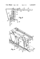
- FIG. 2 is a fragmentary and enlarged cross-sectional view taken as if along the line 2--2 in FIG. 1 but with a revision of one component;
- FIG. 3 is a view similar to FIG. 2 but illustrating modifications of different ones of the various components
- FIG. 4 is an enlarged, fragmentary and partially exploded isometric view, with certain of the components omitted, of the embodiment depicted in FIG. 2;
- FIG. 5 is a view similar to FIGS. 2 and 3 but showing another embodiment of various components
- FIG. 6 is an enlarged vertical cross section of a sign assembly similar to that shown in FIG. 1 but illustrating still different alternative embodiments of a number of different components;
- FIG. 7 is a view similar to FIG. 5 but showing yet another embodiment of various components.
- FIG. 1 An overall display sign assembly 10 is shown in FIG. 1 as mounted on the top of a post 12. Its main framework or cabinet is composed of space-opposed upper and lower support elements joined between corresponding opposite ends by respective side support elements. In FIG. 1 only upper support element 14 and one side support element 16 is visible. Even then, what actually is seen in FIG. 1 are cover plates 18 and 20 each of which is removably secured by screws 22 to an underlying portion of the basic framework. Each of the lower and other side support elements, not seen in FIG. 1, may be identical except, of course, for the coupling that is affixed to the top of post 12.
- all of the support elements be cut from the same stock material after which they are mitred or otherwise formed at their corners and successively joined one to the next in order to complete the rigid framework. Nevertheless, it may be preferred for other reasons to include differences between various ones of the support elements. For example, a cover plate usually is not necessary on all four sides for the purpose of providing access to the interior.
- the terms "upper”, “lower” and “side” are somewhat arbitrarily assigned for the purposes of reference during the discussion, although they have been selected to represent what is probably the most common orientation of a rectangular sign. Obviously, the sign could, for example, be so oriented that its longer sides define the vertical dimension.
- a display face 24 upon which is printed decoration 26 Stretched across the visible main surface of sign assembly 10 is a display face 24 upon which is printed decoration 26.
- the decoration is simply the letters ABC.
- display signs it may be of any character, including a pictorial, numbers or graphics.
- retainer 28 Surrounding the perimeter of display face 24 and also of the framework is a bezel or retainer 28.
- the term "retainer" is mentioned herein only because that is the commonly accepted name in the industry for the part which appears in its position as illustrated.
- retainer 28 is composed of space-opposed upper and lower members 30 and 32 joined between corresponding opposite ends by respective side members 34 and 36 and all affixed to the main framework by screws 38.
- FIG. 1 is merely illustrative. As drawn, its exterior appearance is more or less fully consistent only with the embodiment detailed in FIG. 3. A glance at FIGS. 2, 5 and 7 will reveal, for example, differently-shaped retainers, and it will be observed that FIG. 6 particularly has a distinct difference in the shape of the display face.
- display face 24 is made from a stretchable fabric 40.
- fabric 40 is a soft, cloth-like sheet of polyvinyl chloride reinforced by an internal matrix of fiberglass strands. Particularly desirable is the PANAFLEX fabric described in the introduction. It presents a smooth finish and also is translucent to the illumination as conventionally emanating from fluorescent lamp tubes disposed within the interior of the sign cabinet or framework.
- Interior illumination is contemplated for use in connection with all embodiments. Of course, it will always be possible to omit the interior source of illumination and, instead, employ exterior floodlighting or employ the sign only for daylight viewing. It also is contemplated throughout that the sign assembly is to have a display face 24 forming each of its space-opposed major surfaces. In some cases, however, the opposite display face is omitted as in the case where the back of the sign is to be mounted against the surface of a wall. In that situation, it would be desirable to cover the backside of the sign assembly with a less expensive material such as sheet metal.
- an upper support element 14 is an aluminum extension with a cross-sectional shape that is almost identical to that of the aluminum extrusions employed as support elements in the disclosure of the aforesaid U.S. Pat. No. 4,007,552. For that reason, and also to indicate background considerations and minor modifications that may in a given instance be desired, that patent is incorporated herein by reference. Because a large number of display signs are presently in use that include support members having essentially the same cross-sectional shape as that disclosed in the patent, the embodiment of FIG. 2 is particularly intended to be used in those situations where it is desired to retrofit an existing display sign that has a rigid plastic display face with a display face made of the stretchable fabric to which all embodiments of the present invention are addressed.
- support element 14 has a cross-sectional shape in the general form of an outwardly-opening U-shaped channel.
- fluorescent lamp sockets and a ballast transformer are carried on its bottom wall 42 and the channel defines a raceway in which the inter-connecting wiring is housed.
- the margin of bottom wall 42 continues into an upwardly sloping wall 44 that merges into a side wall 46, defining an exteriorly facing surface 48 and terminating in a ledge 50.
- ledge 50 defined immediately inside ledge 50 is a groove or recess 52 from which an inset side wall portion 54, that presents an exteriorly-facing surface 56, continues upwardly and then is bent inwardly to define a shelf 58.
- the extruded material is shaped to define a rain-drainage channel 60 and then turns back re-entrantly to form another shelf 62 on which an edge margin of cover 18 is disposed and secured by screws 22.
- a retainer 64 has an inner margin 66 which is secured by screws 38 over shelf 58 and continues substantially beyond side wall portion 54 before turning downwardly as a border 68 and on into a panel 70 that slopes back toward the display face and then terminates in a re-entrantly-shaped hook portion 72.
- a lug 74 Projecting downwardly from the inside of retainer 64 immediately beyond its edge margin 66 is a lug 74 that serves to enable proper alignment on installation of the retainer.
- the shape of lug 74 is from an earlier approach in which it served to trap a portion of hardware described in the introduction for mounting grommets. It also would serve to retain a corrugated rigid plastic face.
- retainer 64 is basically the same retainer as disclosed therein.
- One purpose of including it in FIG. 2 is to point out that, in retrofitting an existing sign constructed in accordance with the teachings of the patent, even a retainer based on the original sign system may continue to be used.
- sloping panel 70 of the retainer continues to serve as an attractive feature in defining what may be called a "picture frame" appearance.
- the arrangement of FIG. 2 includes a hinge or saddle 78 that is affixed to support element 14 and within which a hinge pin or tensioner 80 is mated for rotation.
- hinge pin 80 is of generally C-shaped or horseshoe-like cross section, so as to be hollowed out to define an interior cavity 82 within which marginal portion 76 is secured.
- wedge 84 Disposed within cavity 82 is a wedge 84, in this case in the form of a dowel or cylinder with a cross-sectional area less than that of the main portion of the cross section of hinge pin 80 but yet which is of a width greater than the distance between the free ends of the hinge pin at the mouth 86 thereof.
- wedge 84 is captivated or captured within cavity 82 by mouth 86.
- Marginal portion 76 is led into and out mouth 86 and partially wrapped around wedge 84 to reside between the wedge and the inner of hinge pin 80 which defines cavity 82.
- wedge 84 serves as a keeper and cooperates with hinge pin 80 to permit adjustment between a first condition wherein portion 76 is fixed in position relative to the hinge pin and a second condition wherein that marginal portion is movable relative to the hinge pin.
- the tight fit of wedge 84 within mouth 86 causes it to secure itself against and thereby fix the position of marginal portion 76 in response to tension which is developed within fabric 40 upon stretching thereof.
- Hinge 78 includes a segment 90 against the inner surface of which hinge pin 80 is nested.
- segment 90 embraces less than one-half the distance around hinge pin 80. It will be observed that the concave inner surface of segment 90 faces away from the central portion 92 of the resulting display face, with fabric 40 continuing away from hinge pin 80 and marginal portion 76 directly into the formation of central portion 92.
- the outer end 94 of segment 90 is disposed adjacent to and yet spaced from fabric 40. With the source of illumination disposed within the framework of which support element 14 is a part and, thus, inside of the display face formed by fabric 40, end 94 of segment 90 defines an edge of the area of illumination of the display area which constitutes the central portion of fabric 40.
- Mouth 86 flares slightly apart at its outer end so as to define at one side an abutment 96 on the outer wall of hinge pin 80. Upon engaging segment end 94, abutment 96 defines one limit for the extent of rotation of hinge pin 80.
- Finger 98 Integrally affixed to and projecting away from hinge 78 at the other end of segment 90 is a finger 98.
- Finger 98 is in the form of a web and, in the condition illustrated in FIG. 2, has one side which lies flat against surface 48 of support element 14.
- a cleat 100 projects from finger 98 and projects over ledge 50 in order to seat in recess 52. With fabric 40 under tension, that seating of cleat 100 in recess 52 is sufficient to retain hinge 78 in a fixed position.
- a bracket 102 also projects away from finger 98 and presents a flat portion against the surface 56 of upper side portion 54, with a rivet 104 or other suitable fastener securing bracket 102 firmly to support element 14 and thereby prohibiting possible dislodgement of hinge 78.
- a lever 108 is integrally affixed at one end to and projects away from hinge pin 80. In the position shown in FIG. 2, lever 108 lies alongside finger 98 so as thereby to define another limit of rotation of hinge pin 80. This limit, and the one established by the engagement of abutment 96 with segment end 94, serves to restrict the amount of rotation of hinge pin 80 to but a fraction of one revolution.
- a keeper 110 is engageable around the free end of lever 108 and finger 98.
- finger 98 is shaped to define a recess 112, and keeper 110 has an in-turned end portion which is engaged in recess 112.
- marginal portion 76 is threaded into mouth 86, around wedge 84 and then back out of mouth 86. With wedge 84 loose within cavity 82, or even forced to approximately the center of the cavity, marginal portion 76 may be pulled through as desired with respect to either the positioning of that part of the marginal portion being worked upon or with respect to the inducement of tension within fabric 40. In applying tension to fabric 40, it typically tends to gather in places and form wrinkles. Those may be readily smoothed out by releasing wedge 84 from its securing position and, beginning at the center of a margin, wiping the outer surface of fabric 40 to move the material away from the center and outwardly toward an end of that margin.
- both hinge 78 and hinge pin 80 are continuous throughout a margin of the display face.
- hinge pin 80 is comparatively narrow in width, with one inch being exemplary. Consequently, a plurality of hinge pins 80 are successively spaced along the length of that margin, a suitable spacing for a sign of average size being approximately every twelve inches. For larger signs in which greater tension forces are developed, less spacing is preferred.
- hinge 78 also could be so divided into such a succession of individual hinges. However, this latter alternative may make it more difficult to properly adjust with respect to freedom from wrinkling, and it also would create a discontinuity in the edge of the field of illumination that otherwise, as noted above, is defined by segment end 94.
- all four of the support elements be formed to have the same cross section, as by being cut from a common length of stock. They desirably are joined in a mitred condition at each pair of successive ends. That may be achieved either by direct welding of the mitred ends or by the use of internally disposed right-angled brackets heliarc welded or otherwise secured to each of the successive support elements.
- the hinges and hinge pins along all four sides of the display face also be identical, as are all other associated parts. In any case, that identity of parts as around the entire margin is the form of the embodiment disclosed herein.
- Wedge 84 is then inserted, and lever 108 thereafter is rotated back toward its locked position while the marginal portion is pulled upon to cause the wedge to secure the fabric within the mouth.
- lever 108 thereafter is rotated back toward its locked position while the marginal portion is pulled upon to cause the wedge to secure the fabric within the mouth.
- the different ones of wedges 84 are successively released at which time that part of the captivated marginal portion is pulled further through cavity 82 in order to increase tension in fabric 40, while at the same time being moved sideways any slight amount necessary to remove wrinkles.
- the tension in fabric 40 keeps the wedge drawn into the associated mouth to secure the contained fabric into a fixed position.
- the arrangement of the embodiment of FIG. 2 includes further features which negate the need for such possible modifications as have just been suggested except possibly in unusual cases.
- the part of the marginal portion contained therein may be slackened simply by pulling lever 108 forwardly and away from finger 98. That serves to release the securing action of wedge 84 and permit fabric 40 to be adjusted at that location.
- it permits a new "bite" to be taken so that, upon swinging lever 108 backwardly to again position it against finger 98, the tension in fabric 40 is increased.
- a ratchet-type action may be obtained by successively swinging lever 108 back and forth and correspondingly with that motion causing release and thereafter re-engagement of wedge 84 in sequence therewith.
- keeper 110 is slid into place so as to thereby lock hinge pin 80 into its limit position with lever 108 disposed against finger 98.
- wedge 84 may have other than a cylindrical cross section in order to increase the degree of its wedge action. In any case, its exterior surface may be serrated to increase its gripping function as may the interior surface of hinge pin 80. Also, wedge 84 may be fabricated from wood, metal or other material. Nevertheless, in using the described PANAFLEX fabric, fully satisfactory performance has been indicated with wedge 84 fabricated simply as a smooth-finished wooden dowel and with cavity 82 also presenting a smooth surface.
- each keeper 110 be constrained from moving downward by gravity as might occur in the presence of vibration.
- a fine wire may be looped around each such clip and secured at each end by a screw or other fastener.
- the free end portion of lever 108 may be slightly extended and bifurcated so as to receive and captivate a keeper 110 modified so as to be that much less in width.
- hinge pin 108 usually will vary between a little less than one inch and perhaps three inches. It will be observed that an increase in the radius of the hinge and hinge pin will result in obtaining a greater degree of tensioning action with each ratchet-like operation of lever 108. Of course, the greater the tension that has been induced, the tighter the clamping action imposed by wedge 84. If desired in order to lock wedge 84 in place after all tensioning has been completed, a thin tapered member may be placed in the bottom of cavity 82 so as to make it impossible for the wedge to move inwardly from its secured position within mouth 86.
- hinge 78 permits implementation of the present mounting system to support elements of a form basically as shown in the cross-referenced patent.
- hinge 78 may be extruded or otherwise formed to include members of whatever shape is required to interfit with or attach to a framework support element of any kind of exterior configuration.
- element 14a again is shaped generally as an outwardly-opening U-shaped channel, so as to include a bottom wall 42 that merges into an upwardly sloping wall portion 44. The latter continues into a lower side wall portion 120 and then an upper side wall portion 122 which turns into a shelf 58a and thereafter defines a cavity 60 and another shelf 62 to which access cover 18 is affixed by screws 22.
- Retainer 30 is of L-shaped cross section and includes a downwardly projecting lug 124 that comes into alignment against a lip 126 which projects outwardly from upper wall portion 122.
- recess 130 may be shaped and oriented like recess 112 in FIG. 2, so as to permit use of keeper 110 of that version. This permits the economy of using a standard part for both arrangements. Moreover, the additional cleat portion on keeper 110 tends to achieve a more secure interlock.
- hinge 80 and wedge 84 are the same as those parts of FIG. 2, so as also to have leg 108. Accordingly, keeper 132 serves to secure lever 108 in a fixed position at one limit of rotation of hinge pin 80. In this case, however, what was finger 98 in FIG. 2 is merged into side wall portion 120 so as to be one and the same.
- hinge 78a includes a segment 90a which projects integrally away from support element 14a at the junction between sloping panel 44 and side wall portion 120. Segment 90a continues around hinge pin 80 a distance less than one half the circumference thereof and again terminates in an end 94 that has the same functions as before. It will be immediately apparent that installation and adjustment of fabric 40 in the embodiment of FIG. 3 may proceed in exactly the same way as described above for the embodiment of FIG. 2.
- FIG. 5 illustrates an embodiment modified to permit adaptation to a typical cabinet fabricated in that manner.
- a support element 14b includes an angle iron 140 one leg 142 of which is oriented to define a side wall of the interior channel.
- Angle iron 140 may be welded to a cross plate 144 which connects to a similar angle iron at the other side.
- An exterior sheet metal skin 145 covers cross plate 144 and angle iron 140, is bent inwardly, and then continues on downwardly at the lower margin of angle iron 140 so as to define an edge 146 of an illuminated area.
- a retainer 148 is secured through skin 145 to angle iron 140 by a screw 150 and continues on outwardly until bending back to define a downwardly and backwardly sloping panel 152 crimped at its lower end 154 in order to form a re-enforcing rib.
- another steel cross plate is disposed between the side walls to provide added strength and a mounting for lamp sockets.
- hinge pin 80 and wedge 84 are identical in form to those elements as shown in FIG. 2.
- hinge 78b includes an also identical segment 90 which terminates in a free end 94 and at its other end continues into a finger 98b.
- Finger 98b is the same as finger 98 in FIG. 2 except for the provision of a cutout 156 defined in the outer end portion of finger 98b and on the side thereof that is held against skin 145 by screws as shown.
- Lever 108 of hinge pin 80 is secured in one limit position against finger 98b by a downwardly-facing U-shaped clip 158 which has one leg seated in cutout 156 and extends around the free end portions of lever 108 and finger 98b.
- the mounting and adjustment of fabric 40 may be exactly the same as already described for the embodiment of FIG. 2.
- a support element 14c is an aluminum extrusion that again defines internally a U-shaped channel but which in this case opens inwardly of the ultimate sign cabinet.
- the extrusion includes an upper wall 174 joining space-opposed side walls 176 and 178. Displaced a short distance below upper wall 174 are an opposed pair of facing lugs 180 and 182.
- wall 174 which is the upper wall of upper support element 14c, becomes the bottom wall of the framework when inverted and appropriately spaced apart.
- the side support elements of the resulting framework also are cut from the same extruded stock, and all of the different support elements are joined successively end to end so as to define the ultimate cabinet.
- lugs 180 and 182 serve to define recesses in which appropriate steel or aluminum corner angles preferably are received and bolted or heliarc welded to the respective support elements so as to form strong, rigid corners of the framework.
- steel plates are of an appropriate width to slide under lugs 180 and 182 along the bottom and top margins after which they are bolted in place. Later, a steel pipe or tube is inserted through an opening in the bottom support element and that plate to dispose its upper end against the steel plate mounted to the top support element. The pipe is then welded to both steel plates and subsequently serves to connect the entire display sign upon the upper end of post 12 or to an equivalent support.
- lugs 184 and 186 Projecting inwardly from about the midportion of side wall 176 are a pair of vertically spaced lugs 184 and 186 with lug 186, closest to lamp 170, having a length shorter than lug 184. Spaced opposite lugs 184 and 186 is an inwardly projecting shelf 188.
- one edge margin of a plate 190 is inserted between lugs 184 and 186 after which its other edge margin is swung toward and against shelf 188 against which it is secured in place by means of a screw 192.
- Plate 190 thus defines a removable access cover and contains suitable apertures within which the lamp sockets 172 are mounted and captivated. Screws 192 or equivalent fasteners are required only along one margin of plate 190, thereby reducing labor otherwise required to drill and fasten the other margin.
- Outer wall 174 continues beyond each of side walls 176 and 178 so as to define respective projecting lips 194 and 196 each of which is forked at its outer end portion 198. Seated within each of forks 198 is the shorter leg of an L-shaped retainer 200 the longer leg of which projects toward the display face.
- hinge pin 204 is of C-shaped cross section so as to define a mouth 206 of an interior cavity within which is captivated a wedge 208.
- the adjacent marginal edge portion 210 of fabric 40 is threaded into mouth 206 and around wedge 208 after which it emerges from the other side of the mouth.
- hinge 202 has a segment 212 which presents a concave interior surface so as to serve the same purpose as segment 90 in FIG. 2 but which herein embraces in excess of one half the distance around hinge pin 204, so that the latter may be captivated within segment 212.
- Segment 212 terminates in a rounded shoulder 214 that defines, with the opposite finger 216, a gap which has a width that permits snug entry of hinge pin 204. Because shoulder 214 projects upwardly beyond the axis of hinge pin 204, tension induced in fabric 40 forces the hinge pin to remain seated in hinge 202.
- a lip 218 is integrally affixed at one end to and projects away from hinge pin 204 from the side of mouth 206 more distant from finger 216.
- a flange 220 Projecting outwardly from hinge 202 at shoulder 214 is a flange 220, the free end portion 222 thereof being turned inwardly toward the lower framework support element.
- Lip 218 projects outwardly from hinge pin 204 in a direction away from support element 14c a distance greater than the distance by which flange 220 projects away from that support element. That is, the free end of lip 218 is spaced beyond the free end of flanges 220.
- the outer or free end portion of lip 218 is also bent toward the lower or opposite framework support element.
- Fabric 40 continues from marginal portion 210 as a skirt portion 224 that further continues into a central portion 226.
- skirt portion 224 lies adjacent to the side of lip 218 opposite flange 220, and central portion 226 is directed toward the lower support element.
- the opposite and lower support element includes a fastener 230 for the opposed marginal portion 232 of fabric 40.
- Fastener 230 includes an L-shaped bracket 233 the longer leg of which in use is abutted against side wall 176 and its continuation as finger 216.
- the shorter leg of bracket 233 continues outwardly away from the support element into a lip 234 that overlies flange 220.
- the outer or free end portion of lip 234 projects away from the lower support element a distance greater than the outer end of flange 220 and is turned in this case upwardly toward the upper support element and central portion 226 of fabric 40.
- the longer leg of bracket 233 is secured to side wall portion 176 by a screw 238.
- screw 238 also serves to removably affix lip 234 indirectly to the lower support element.
- fastener 230 Also included in fastener 230 is a removable resilient clip 240 which is shaped to clamp a captured marginal portion of fabric 40 to lip 234. To that end, lip 234 is formed to define a latch surface on the free end of a stub 242 and which is lockingly engageable with a latch member 244 defined in clip 240. A part of marginal portion 232 is clamped between that latch surface and that latch member, so that marginal portion 232 is secured to lip 234. Thus, marginal portion 232 is then fixed into position with respect to the lower support element.
- Clip 240 is shaped further to define another latch member in the form of a C-shaped end portion 246 which is disposed to embrace a rounded terminal portion 248 defined on the outer end of a strut 250 that projects away from bracket 233 and outwardly from the lower support element as well as in a generally downward direction.
- Marginal portion 232 of fabric 40 is also clamped between latch member portion 246 and the latch surface defined by rounded terminal portion 248.
- Terminal portion 248 is another form of hinge pin, while end portion 246 serves as a hinge.
- clip 240 is placed against the outside of marginal portion 234 at a desired distance from the free edge of the marginal portion. End portion 246 is then placed over terminal portion 248 with the fabric therebetween. Clip 240 thereafter is rotated around terminal portion 248 until latch member 244 is snapped into engagement with the latch surface on stub 242 to complete the clamping of the fabric in place. As clip 240 is rotated around terminal portion 248, tension is induced in fabric 40.
- the remaining pair of support elements which serve as the vertical side margins, preferably also include fasteners 230 arranged in the same manner.
- lip 234 projects outwardly from the lower support element and in a direction that is generally lateral to the resulting display face.
- Fabric 40 continues from its lower marginal portion in FIG. 6 again as a skirt 224 which continues into central portion 226 with skirt 224 lying against the side of lip 234 opposite upper support element 14c.
- Flange 220 also projects outwardly from the lower support element in a direction generally laterally to the ultimate display face and is disposed on the side of lip 234 toward upper support element 14c. With fabric 40 stretched in tension, lip 234 is slidable over flange 220 which cams lip 234 into a position whereat the lip is affixed indirectly to the lower support element by means of bracket 233. It will, of course, be noted that flange 220 projects directly away from what constitutes hinge 212 in upper support element 14c. When segment 212 need not be included in which case flange 220 could project directly away from finger 216.
- clips 240 are thus removable at any location along a margin of the display face, so as to permit the adjustment of tension in fabric 40 as well as movement of different parts of the associated marginal portion of that fabric for the purpose of adjusting against wrinkling. That is, selected sections of a marginal portion may be moved in a direction along the length of the corresponding support element as necessitated.
- the entire fastening assembly includes a plurality of lips 218 and 234 that fasten corresponding ones of the different marginal portions of fabric 40 to respective ones of the support elements, the fabric continuing from each of the different marginal portions as a skirt that overlies the corresponding one of the lips and further continuing around the free end portion of that lip into a common central portion.
- Another function of the outer end portions of lips 218 and 234 is to space central portion 226 of each display face the correct distance from lamps 170 as discussed above for the purpose of obtaining uniformity of illumination while yet avoiding the need for provision of support elements of any greater width.
- all of those lips 218 and 234 are continuous and are joined in succession one to the next to define a frame 260 that it matable with the framework formed by the succession of support elements.
- the various flanges 220 also are included all of the way around the perimeter of the display face, and each is disposed on the side of its corresponding lip opposite skirt 224. With the corresponding marginal portions individually fastened to respective different ones of the lips and fabric 40 stretched under tension on frame 260, hinge pin 204 is set into hinge 202 along the upper support element. Of course, all of retainers 200 on that face side are at this time removed. The bottom margin of frame 260 is then swung toward the lower support element. During that movement, flanges 220 on the lower and side support elements cam the entire frame into a position adjacent to the framework.
- flange 220 along the upper support element may assist in the operation by at least guiding hinge pin 204 toward its seat within hinge 202. Should it for any reason be desirable to seat hinge pin 204 in hinge 202 at the same time as or after the placement of the remainder of frame 260 against the lower and side support elements, flange 220 along the upper support element is so shaped and oriented that it will cam hinge pin 204 into the position necessary to drop into hinge 202. In any case, either the disposition of hinge pin 204 within hinge 202 or the affixation of bracket 233 against its associated support element serves to secure frame 260 to the main framework.
- hinge pin 204 and hinge 202 along upper support element 14c permits the entire top margin of frame 260 to be hingedly secured along that upper margin of the main framework.
- securement provided by bracket 233 or the equivalent serves to hold frame 260 in closing relationship with the framework.
- frame 260 is formed by joining together the different lips 218 and 234 before deliverly to the work site.
- the joinder of the successive ends of lips 218 and 234 in order to form frame 260 may be made directly by heliarc welding and with no need for additional corner supports.
- fabric 40 may be mounted upon frame 260 with only a sufficient degree of tension therein to hold the fabric in place on the frame. With the main framework or cabinet already installed, the thus assembled frame with fabric 40 mounted is then slipped over the combination of all of flanges 220 as described above.
- a longer form of screw 238 may be used to draw lower lip 234 over its lower flange 220 until the longer leg of bracket 233 is disposed against the lower support element. Then, different ones of the succession of the longer form of screws 238 are removed and replaced by the shorter screws so that their inner ends will not penetrate into the wiring. Accordingly, the final form of screws 238 ultimately serve to secure the entire frame to the framework defined by the different ones of the support elements.
- the upper marginal portion 210 of fabric 40 desirably is first adjusted, by loosening wedge 208, to what is to be the final position of that marginal portion.
- individual different ones of clips 240 are unlatched and that part of lower marginal portion 232 is then adjusted laterally to smooth out wrinkles and also to eventually reach the finally desired tension in fabric 40.
- the one of clips 240 overlying that section is again snapped into place after which the next one of the clips is removed so that its section of the lower margin may be adjusted.
- the very same procedure is employed along the vertical side margins of the display face. In reaching final tension adjustment, the installer preferably alternates between adjustment in the horizontal direction and adjustment in the vertical direction.
- a line preferably is defined, either temporarily by the use of chalk or permanently by printing, across the exterior surface of fabric 40 and parallel to what will be a nearby support element.
- Such a line should be defined adjacent to at least one horizontal support element and one vertical support element, although it may be defined all of the way around the perimeter. For illustration, that line will be discussed in connection with fastener 230 along the lower margin.
- a specific location on fastener 230 is selected as a reference point. Conveniently, that may be at the bend 264 between latch members 244 and 246.
- the line which is defined on the exterior surface of fabric 40 initially is located in a position exposed to view from the front exterior of the display face when the tension in fabric 40 is substantially removed.
- location of the line is such that, upon increasing the tension in fabric 40, the line is moved toward the reference point defined by bend 264.
- the line is so located relative to lower marginal portion 232 at its outer end that, upon achieving the tension ultimately desired, that line has been moved into a final position against bend 264.
- clip 240 may be latched into place for the final time. Thereafter, access to the interior of the sign cabinet requires only the removal of screws 238 along the bottom and side margins. This permits frame 260 to be swung out from the bottom and in hinge 202 without disturbing the tension established in fabric 40.
- skirt 224 entirely around the perimeter of central portion 226 of the resulting display face serves to give the appearance of the "molded pan look" discussed earlier.
- flanges 220 may be merged into lips 218 and 234 to provide only one skirt-defining and outwardly projecting pan-forming member. This is not as desirable, however, because the separate existance of flanges 220 serves as additional support for lips 218 and 234. Because of flanges 220, frame 260 may in itself be of a more lightweight construction.
- lips 218 or 234 and their respective components may be used independently along any given support element similarly to the use of independent hardware in the embodiments of FIGS. 2-5.
- Lip 218 in that case serves as a lever similar in fucntion to lever 208 although of somewhat different shape and projecting from the opposite side of the mouth of the hollow hinge pin.
- flange 220 constitutes a stop carried by support element 14c and which is disposed in the path of lip 218 to define a limit of rotation of hinge pin 204.
- the lower end of the longer leg of retainer 200 would constitute a stop disposed in the swing path of lip 218 so as to define another limit to the rotation of hinge pin 204.
- hinge pin 204 With fabric 40 under tension in this independent alternative and hinge pin 204 initially located apart from hinge 202, flange 220 agains is oriented to defined a cam surface over which hinge pin 204 may be slid and then inserted around shoulder 214 and into hinge 202. That same tension already induced in fabric 40 also serves to lock hinge pin 204 against rotation by constraining lip 218 to lie against flange 220.
- hinge 202 preferably is continuous over its length along support element 14c as is hinge pin 204. Otherwise, at least hinge pin 202 and wedge 208 may be in successive segments as in the version of FIG. 2. It will be apparent that initial installation of fabric 40 in this case may proceed on the same basis as described in connection with FIG. 2.
- marginal portion 210 may be first inserted around wedge 208 after which lip 218 is rocked back and forth in a ratchet-like fashion with a related acton upon wedge 208 or in a manner otherwise to use lip 218 to slacken the tension and thereby permit adjustment of marginal portion 210.
- one or more of the other support elements may be used like upper support element 14c so as to include hinge 202 and be associated with hinge pin 204 and wedge 208.
- fasteners 230 may be used with any support element to serve as means for adjusting tension in fabric 40.
- FIG. 7 shows still another embodiment which is particularly useful with either existig sign cabinets or new cabinets of the same conformation.
- the cabinet is basically of rectangular cross section and in this case also has a framework made from steel members.
- a support element 14d includes an angle iron 170 one leg 172 of which is oriented to define a side wall of an interior channel.
- Angle iron 170 is welded to a cross plate 174 which connects to a similar angle iron at the other side.
- An exterior sheet metal skin 175 covers angle iron 170 and cross plate 174 and extends on inwardly of the angle iron.
- An L-shaped extruded bracket 178 fits over skin 175 and around angle iron 170, being secured to the latter by screws 180.
- a shelf 182 Projecting outwardly from near the upper end of the longer leg 181 of bracket 178 is a shelf 182 to which a retainer 184 is secured by screws 185.
- Shelf 182 is shaped at its inner end to define a recess 186 in which a down-turned margin 188 is seated.
- a ledge 190 also defined in shelf 182, accommodates a gasket 192.
- retainer 184 is bent downwardly and thereafter reversely to define a concealing border.
- a strut 194 Projecting outwardly from near the lower end of leg 181 is a strut 194 which continues into a hinge 78d again having a segment 90 with a free end 94.
- a hinge pin 80d similar to hinge pin 80 and nested in hinge 78d, has a lever 108d that may be locked in a vertical position by a keeper 110d.
- keeper 110d may be identical to keeper 110 of FIG. 2.
- keeper 110d is shaped to bend around the outer end of lever 108d and terminates in a re-entrant portion that seats in a recess 196 defined in a J-shaped stub 198 which projects outwardly from leg 181 between shelf 182 and strut 194.
- the free end portion of lever 108d abuts the outer end of stub 198.
- hinge pin 80d At the side of mouth 86d opposite lever 108d, the wall of hinge pin 80d continues into a lip 200 that projects on outwardly in the direction away from support element 14d. Lip 200 curves smoothly to present an upwardly-facing convex surface 202 and terminates in a free end which is spaced outwardly beyond end 94. Upon removal of keeper 110d, lever 108d may be moved forwardly to rotate hinge pin 80d until lip 200 abuts end 94 as a limit of rotation.
- wedge 84 is disposed within hinge pin 80d to function in some manner discussed above.
- the mounting and adjustment of fabric 40 may be exactly the same as described in connection with the embodiment of FIG. 2.
- lip 200 also serves a function analogous to a feature of lip 218 in FIG. 6. That is, marginal portion 76 continues into a skirt portion 204 that overlies surface 202 on lip 200 before the fabric turns downward to define the illuminated display face.
- lip 200 By virtue of the provision of lip 200, the display face is spaced farther from the main framework of the cabinet than in the embodiments of FIGS. 2-5. In retrofitting an existing cabinet, that may be desirable to improve overall appearance or to obtain better uniformity of illumination in the manner explained above. If made to be sufficiently rugged, lip 200 could, in principle, be extended so as also to yield a "pan shaped look" to the display face. However, it appears to be preferable to achieve that result by the use of the arrangement of FIG. 6 wherein lip 218 is supported on flange 220, adapting that approach as necessary to accommodate either an existing sign cabinet when retrofitting or a new cabinet of still different cross-sectional shape.
- one purpose of being able to release at least some tension in different sections of a marginal portion is to allow smoothing of fabric 40 so as to remove wrinkles.
- a pictorial display printed upon the display face it might actually be desired in a specific case that a certain amount of wrinkling in a selected portion of the display face be caused to occur deliberately for the purpose of modifying the image visualized by a limited shadowing or other effect.
- the adjustable fastening and hinging devices described permit that result.
- each of hinge pins 204 or clips 240 is sufficiently narrow that it still may be shaped to define surfaces across its width that are straight.
- a curved margin may be caused to appear by mounting a bezel around the perimeter of the display face which in itself has a straight mounting member but with the bezel defining an illuminated area as viewed which has a curved margin.
- Such a bezel may be part of an extension of the retainer.
- the inwardly directed and free end of one or more of lips 218 and 234 may be curved so as to define an illuminated margin of that shape.
- any such addition of a curved or other marginal feature might also include different formations such as scallops.
- FIG. 6 is essentially a new version and features integration of flange 220 and hing 202 into the corresponding support element of the primary framework. While that definitely is the preferred approach, it should be apparent that flange 220 and hinge 202 may alternatively be joined to a separate member fully analogous to finger 98 of FIG. 2 or finger 98b of FIG. 5. Thus, there would be a separate part securable to the side wall of a new or an existing older form of main framework support element in the same or an equivalent manner to that discussed in connection with FIGS. 2 and 5. In this way, older forms of support elements may be retrofitted to adapt the improvements featured in FIG. 6 such as the attainment of the "molded pan look" and/or the separate formation of frame 260 that is hingeably secured along one margin of the framework.
- the display face may be swung or otherwise moved away from the framework to allow access to the interior.
- the entire, display face may be swung away without disturbing the previous adjustment of tension and smoothness. While mechanical distortion and wind damage must be avoided, the overall construction permits the use of a separate frame that in itself is lightweight.
Abstract
Description
Claims (82)
Priority Applications (5)
| Application Number | Priority Date | Filing Date | Title |
|---|---|---|---|
| US06/069,222 US4265039A (en) | 1979-08-23 | 1979-08-23 | Display signs |
| CA000356611A CA1149159A (en) | 1979-08-23 | 1980-07-21 | Display signs |
| CA000428048A CA1170048A (en) | 1979-08-23 | 1983-05-12 | Display signs |
| CA000428049A CA1170049A (en) | 1979-08-23 | 1983-05-12 | Display signs |
| CA000428050A CA1170050A (en) | 1979-08-23 | 1983-05-12 | Display signs |
Applications Claiming Priority (1)
| Application Number | Priority Date | Filing Date | Title |
|---|---|---|---|
| US06/069,222 US4265039A (en) | 1979-08-23 | 1979-08-23 | Display signs |
Publications (1)
| Publication Number | Publication Date |
|---|---|
| US4265039A true US4265039A (en) | 1981-05-05 |
Family
ID=22087528
Family Applications (1)
| Application Number | Title | Priority Date | Filing Date |
|---|---|---|---|
| US06/069,222 Expired - Lifetime US4265039A (en) | 1979-08-23 | 1979-08-23 | Display signs |
Country Status (2)
| Country | Link |
|---|---|
| US (1) | US4265039A (en) |
| CA (1) | CA1149159A (en) |
Cited By (58)
| Publication number | Priority date | Publication date | Assignee | Title |
|---|---|---|---|---|
| US4430819A (en) * | 1981-11-12 | 1984-02-14 | Chandler Vernon P | Display sign assembly |
| EP0132305A1 (en) * | 1983-06-23 | 1985-01-30 | Maxwell W. Stokes Advertising Pty. Ltd. | Tension device |
| US4516343A (en) * | 1983-01-18 | 1985-05-14 | Johann Stilling | Sign structure |
| US4554754A (en) * | 1984-07-06 | 1985-11-26 | Johann Stilling | Sign with flexible face |
| US4665671A (en) * | 1986-03-28 | 1987-05-19 | American Floor Covering Company | Method for assembling an awning |
| US4674213A (en) * | 1985-04-01 | 1987-06-23 | Cliff Keithley | Extruded aluminum sign frame section |
| GB2201024A (en) * | 1987-01-09 | 1988-08-17 | Colorlux As | An illuminated sign box |
| US4800947A (en) * | 1987-09-21 | 1989-01-31 | Joseph K. Favata | Tension mounting system and assembly |
| US4802296A (en) * | 1986-12-30 | 1989-02-07 | Signcomp, Inc. | Architectural sign system |
| WO1989002495A1 (en) * | 1987-09-21 | 1989-03-23 | Aero Wabash, Inc. | Tension mounting system and assembly |
| US4817317A (en) * | 1986-12-30 | 1989-04-04 | Signcomp, Inc. | Component sign system |
| US4865066A (en) * | 1986-12-16 | 1989-09-12 | Abc Extrusion Company, Inc. | Canopy assembly |
| US4922988A (en) * | 1987-09-21 | 1990-05-08 | Aero Wabash, Inc. | Tension mounting system and assembly |
| EP0387030A2 (en) * | 1989-03-09 | 1990-09-12 | Signtech Inc. | Sign assembly |
| US4993982A (en) * | 1986-03-11 | 1991-02-19 | Mid Mountain Materials, Inc. | Method and apparatus for producing neon signs |
| US5020254A (en) * | 1988-02-09 | 1991-06-04 | Sheppard Paul G | Illuminated sign system having tensioning means |
| WO1993012514A1 (en) * | 1991-12-09 | 1993-06-24 | Jarle Hansen | Advertising sign |
| WO1994027272A1 (en) * | 1993-05-07 | 1994-11-24 | Coleman Kelly R | C-channel frame construction for a sign |
| US5398388A (en) * | 1993-05-07 | 1995-03-21 | Coleman; Kelly R. | Tensioning assembly for flexible sign faces and awnings |
| US5467546A (en) * | 1991-04-23 | 1995-11-21 | Signcomp, Inc. | Tensioned fabric sign |
| US5517779A (en) * | 1993-05-07 | 1996-05-21 | Coleman; Kelly R. | Sign face attachment with perimeter flanges for universal mounting |
| US5647155A (en) * | 1995-11-22 | 1997-07-15 | Marketing Displays, Inc. | Sheet tensioning system |
| US5893227A (en) * | 1994-08-29 | 1999-04-13 | Johansson; Goeran | Fabric sign with tensioning means |
| US5992070A (en) * | 1995-04-04 | 1999-11-30 | The Carter-Water Corporation | Flexible face sign system |
| US6070351A (en) * | 1998-08-24 | 2000-06-06 | Verret; Normand | Flexible face sign with raised display surface |
| US6088942A (en) * | 1997-04-11 | 2000-07-18 | Abc Sign Products, Inc. | Method and apparatus for retaining flexible material in a sign system |
| JP2000267608A (en) * | 1999-03-10 | 2000-09-29 | Normand Verret | Flexible face signboard having projecting display surface |
| US6368011B1 (en) | 1999-04-28 | 2002-04-09 | Milliken Industries | Sign box joining device |
| US6370802B1 (en) | 1999-09-16 | 2002-04-16 | Lsi Industries Inc | Back-lit fascia with spring loaded fascia tensioner |
| US6493968B2 (en) | 2000-01-11 | 2002-12-17 | Clyde J. Chinitz | Frame apparatus and method for stretching flexible material |
| WO2003030133A1 (en) * | 2001-10-04 | 2003-04-10 | Johansson Goeran | Fabric sign |
| US20030079434A1 (en) * | 1996-06-27 | 2003-05-01 | Les Milliken | Framing member for use in assembling a bleed sign face construction |
| US6718668B2 (en) | 2002-04-02 | 2004-04-13 | Anthony Cozzilino | Display means and apparatus |
| US6722096B2 (en) | 2002-01-23 | 2004-04-20 | Quanex Corporation | Frame assembly and frame component for tensioning fabric about a panel of a partition system |
| US20040163293A1 (en) * | 2003-02-25 | 2004-08-26 | Hughes Robert P. | Display panels |
| US20040238702A1 (en) * | 2003-05-29 | 2004-12-02 | Britten Paul J. | Bracket for mounting banner to a truck wall |
| US20050091939A1 (en) * | 2003-09-09 | 2005-05-05 | Hillstrom Brian J. | Door assembly for menu board |
| US20050102880A1 (en) * | 2001-11-29 | 2005-05-19 | Sam Cook | Display apparatus |
| CY2447B1 (en) * | 2002-05-09 | 2005-06-03 | Antonis Andreou | Oval advertising plate with low air resistance andan original way of suspension with the support of linoleum. |
| US20050229446A1 (en) * | 2004-04-19 | 2005-10-20 | Jim Bagley | System for securing fabric to a quilting bar |
| US6976330B2 (en) | 2002-04-04 | 2005-12-20 | Milliken & Milliken | Hinge assembly for sign box face |
| US20050279465A1 (en) * | 2004-06-18 | 2005-12-22 | Ted Gower | Structure envelope reinforcement |
| US20060174525A1 (en) * | 2003-02-25 | 2006-08-10 | Hughes Robert P | Fabric display panels and methods of making same |
| US20070236941A1 (en) * | 2006-02-14 | 2007-10-11 | Mark Logan | Illuminated sign insert |
| US20090145011A1 (en) * | 2007-11-27 | 2009-06-11 | Walton Charles M | Signcase system and method for manufacturing same |
| ES2322833A1 (en) * | 2007-06-29 | 2009-06-29 | Jose Manuel Dasi Teruel | System of change of canvas in advertising fences (Machine-translation by Google Translate, not legally binding) |
| KR100959955B1 (en) * | 2009-08-20 | 2010-05-26 | 주식회사 에이엘 | Screen advertisement board |
| US7845103B2 (en) | 2006-02-14 | 2010-12-07 | Acuity Brands, Inc. | Illuminated sign mounting structure |
| US8146647B1 (en) * | 2010-04-13 | 2012-04-03 | Hughes Brian G | Screen clipping system and clips therefor |
| WO2015111294A1 (en) * | 2014-01-24 | 2015-07-30 | 明拓工業株式会社 | Display device |
| US9422732B2 (en) | 2014-04-28 | 2016-08-23 | Ted Gower | Slidable barriers |
| US9512612B2 (en) | 2014-12-05 | 2016-12-06 | Ted Gower | Retainer inserts for barriers |
| US9552751B1 (en) * | 2012-09-26 | 2017-01-24 | Page Barker | Light tower marketing display |
| US9633583B2 (en) * | 2015-06-25 | 2017-04-25 | Apco Graphics, Inc. | Low profile, self-aligning customizable sign and method of displaying customizable information |
| US9715842B2 (en) | 2014-01-27 | 2017-07-25 | Bret Mileski | Self tensioning mounting frame for sheet media |
| US10092116B1 (en) * | 2017-11-16 | 2018-10-09 | Sparkle Life | Jewelry display case |
| US20190211623A1 (en) * | 2018-01-08 | 2019-07-11 | Pgt Innovations, Inc. | Roll-up screen panel |
| US10714912B2 (en) * | 2018-06-11 | 2020-07-14 | Rittal Gmbh & Co. Kg | Switch cabinet with a side panel, a related method and a related bay of switch cabinets |
Citations (17)
| Publication number | Priority date | Publication date | Assignee | Title |
|---|---|---|---|---|
| US1148764A (en) * | 1914-06-27 | 1915-08-03 | Francis D Hagan | Screen. |
| US2378163A (en) * | 1944-03-04 | 1945-06-12 | Radio Patents Corp | Combined screen frame and weather stripping |
| US2573318A (en) * | 1948-06-15 | 1951-10-30 | Dow John | Changeable sign |
| US2897889A (en) * | 1957-05-27 | 1959-08-04 | Kessler Gerald | Screen spline with direct frictional engagement means |
| US3591940A (en) * | 1969-03-19 | 1971-07-13 | John W Slemmons | Supporting frame |
| US3696857A (en) * | 1971-01-21 | 1972-10-10 | Frank M Le Tarte | Panel and frame assembly |
| US3758972A (en) * | 1971-08-09 | 1973-09-18 | G Egermayer | Billboard |
| US3885335A (en) * | 1973-10-23 | 1975-05-27 | George W Egermayer | Sign holding and framing assembly |
| US3934365A (en) * | 1973-02-22 | 1976-01-27 | Esco, Inc. | Sign frame |
| US3978905A (en) * | 1975-09-02 | 1976-09-07 | Lama Alberto De | Canvas stretcher frame |
| US3982345A (en) * | 1972-12-22 | 1976-09-28 | Coleman Kelly R | Display device with flexible face |
| US4007552A (en) * | 1973-09-04 | 1977-02-15 | Abc Extrusion Company | Extruded aluminum sign frame system |
| US4041861A (en) * | 1975-06-02 | 1977-08-16 | Alter David L | Screen printing frame with floating stretch-clamps |
| US4107826A (en) * | 1978-01-23 | 1978-08-22 | Tysdal Daryl D | Flexible covering anchor |
| US4188764A (en) * | 1978-04-03 | 1980-02-19 | Gode Charles R | Prefabricated greenhouse structure |
| US4194312A (en) * | 1978-12-04 | 1980-03-25 | Alpha Nova Engineering, Inc. | Needlepoint supporting frame and clip assembly |
| US4213493A (en) * | 1979-01-24 | 1980-07-22 | Haworth Mfg., Inc. | Fabric retainer for panel |
-
1979
- 1979-08-23 US US06/069,222 patent/US4265039A/en not_active Expired - Lifetime
-
1980
- 1980-07-21 CA CA000356611A patent/CA1149159A/en not_active Expired
Patent Citations (17)
| Publication number | Priority date | Publication date | Assignee | Title |
|---|---|---|---|---|
| US1148764A (en) * | 1914-06-27 | 1915-08-03 | Francis D Hagan | Screen. |
| US2378163A (en) * | 1944-03-04 | 1945-06-12 | Radio Patents Corp | Combined screen frame and weather stripping |
| US2573318A (en) * | 1948-06-15 | 1951-10-30 | Dow John | Changeable sign |
| US2897889A (en) * | 1957-05-27 | 1959-08-04 | Kessler Gerald | Screen spline with direct frictional engagement means |
| US3591940A (en) * | 1969-03-19 | 1971-07-13 | John W Slemmons | Supporting frame |
| US3696857A (en) * | 1971-01-21 | 1972-10-10 | Frank M Le Tarte | Panel and frame assembly |
| US3758972A (en) * | 1971-08-09 | 1973-09-18 | G Egermayer | Billboard |
| US3982345A (en) * | 1972-12-22 | 1976-09-28 | Coleman Kelly R | Display device with flexible face |
| US3934365A (en) * | 1973-02-22 | 1976-01-27 | Esco, Inc. | Sign frame |
| US4007552A (en) * | 1973-09-04 | 1977-02-15 | Abc Extrusion Company | Extruded aluminum sign frame system |
| US3885335A (en) * | 1973-10-23 | 1975-05-27 | George W Egermayer | Sign holding and framing assembly |
| US4041861A (en) * | 1975-06-02 | 1977-08-16 | Alter David L | Screen printing frame with floating stretch-clamps |
| US3978905A (en) * | 1975-09-02 | 1976-09-07 | Lama Alberto De | Canvas stretcher frame |
| US4107826A (en) * | 1978-01-23 | 1978-08-22 | Tysdal Daryl D | Flexible covering anchor |
| US4188764A (en) * | 1978-04-03 | 1980-02-19 | Gode Charles R | Prefabricated greenhouse structure |
| US4194312A (en) * | 1978-12-04 | 1980-03-25 | Alpha Nova Engineering, Inc. | Needlepoint supporting frame and clip assembly |
| US4213493A (en) * | 1979-01-24 | 1980-07-22 | Haworth Mfg., Inc. | Fabric retainer for panel |
Cited By (78)
| Publication number | Priority date | Publication date | Assignee | Title |
|---|---|---|---|---|
| US4430819A (en) * | 1981-11-12 | 1984-02-14 | Chandler Vernon P | Display sign assembly |
| US4516343A (en) * | 1983-01-18 | 1985-05-14 | Johann Stilling | Sign structure |
| EP0132305A1 (en) * | 1983-06-23 | 1985-01-30 | Maxwell W. Stokes Advertising Pty. Ltd. | Tension device |
| US4554754A (en) * | 1984-07-06 | 1985-11-26 | Johann Stilling | Sign with flexible face |
| US4674213A (en) * | 1985-04-01 | 1987-06-23 | Cliff Keithley | Extruded aluminum sign frame section |
| US4993982A (en) * | 1986-03-11 | 1991-02-19 | Mid Mountain Materials, Inc. | Method and apparatus for producing neon signs |
| US4665671A (en) * | 1986-03-28 | 1987-05-19 | American Floor Covering Company | Method for assembling an awning |
| US4865066A (en) * | 1986-12-16 | 1989-09-12 | Abc Extrusion Company, Inc. | Canopy assembly |
| US4802296A (en) * | 1986-12-30 | 1989-02-07 | Signcomp, Inc. | Architectural sign system |
| US4817317A (en) * | 1986-12-30 | 1989-04-04 | Signcomp, Inc. | Component sign system |
| US4864756A (en) * | 1987-01-09 | 1989-09-12 | Colorlux A/S | Illuminated sign box |
| GB2201024B (en) * | 1987-01-09 | 1991-01-02 | Colorlux As | An illuminated sign box |
| AU605308B2 (en) * | 1987-01-09 | 1991-01-10 | Colorlux A/S | An illuminated sign box |
| GB2201024A (en) * | 1987-01-09 | 1988-08-17 | Colorlux As | An illuminated sign box |
| WO1989002495A1 (en) * | 1987-09-21 | 1989-03-23 | Aero Wabash, Inc. | Tension mounting system and assembly |
| US5046545A (en) * | 1987-09-21 | 1991-09-10 | Joseph K. Favata | Tension mounting system and assembly |
| US4922988A (en) * | 1987-09-21 | 1990-05-08 | Aero Wabash, Inc. | Tension mounting system and assembly |
| US4800947A (en) * | 1987-09-21 | 1989-01-31 | Joseph K. Favata | Tension mounting system and assembly |
| US5020254A (en) * | 1988-02-09 | 1991-06-04 | Sheppard Paul G | Illuminated sign system having tensioning means |
| EP0387030A3 (en) * | 1989-03-09 | 1992-01-02 | Signtech Inc. | Sign assembly |
| EP0387030A2 (en) * | 1989-03-09 | 1990-09-12 | Signtech Inc. | Sign assembly |
| US5467546A (en) * | 1991-04-23 | 1995-11-21 | Signcomp, Inc. | Tensioned fabric sign |
| WO1993012514A1 (en) * | 1991-12-09 | 1993-06-24 | Jarle Hansen | Advertising sign |
| WO1994027272A1 (en) * | 1993-05-07 | 1994-11-24 | Coleman Kelly R | C-channel frame construction for a sign |
| US5398388A (en) * | 1993-05-07 | 1995-03-21 | Coleman; Kelly R. | Tensioning assembly for flexible sign faces and awnings |
| US5517779A (en) * | 1993-05-07 | 1996-05-21 | Coleman; Kelly R. | Sign face attachment with perimeter flanges for universal mounting |
| US5572821A (en) * | 1993-05-07 | 1996-11-12 | Coleman; Kelly R. | C-channel frame construction for a sign |
| US5678338A (en) * | 1993-05-07 | 1997-10-21 | Coleman; Kelly R. | Sign including a channel frame construction |
| US5893227A (en) * | 1994-08-29 | 1999-04-13 | Johansson; Goeran | Fabric sign with tensioning means |
| US5992070A (en) * | 1995-04-04 | 1999-11-30 | The Carter-Water Corporation | Flexible face sign system |
| US5647155A (en) * | 1995-11-22 | 1997-07-15 | Marketing Displays, Inc. | Sheet tensioning system |
| US7487610B2 (en) * | 1996-06-27 | 2009-02-10 | Milliken Industries, Inc. | Framing member for use in assembling a bleed sign face construction |
| US20030079434A1 (en) * | 1996-06-27 | 2003-05-01 | Les Milliken | Framing member for use in assembling a bleed sign face construction |
| US6088942A (en) * | 1997-04-11 | 2000-07-18 | Abc Sign Products, Inc. | Method and apparatus for retaining flexible material in a sign system |
| US6070351A (en) * | 1998-08-24 | 2000-06-06 | Verret; Normand | Flexible face sign with raised display surface |
| JP2000267608A (en) * | 1999-03-10 | 2000-09-29 | Normand Verret | Flexible face signboard having projecting display surface |
| US6368011B1 (en) | 1999-04-28 | 2002-04-09 | Milliken Industries | Sign box joining device |
| US6578250B2 (en) | 1999-09-16 | 2003-06-17 | Lsi Midwest Lighting, Inc. | Method for constructing a sign frame assembly |
| US6370802B1 (en) | 1999-09-16 | 2002-04-16 | Lsi Industries Inc | Back-lit fascia with spring loaded fascia tensioner |
| US6493968B2 (en) | 2000-01-11 | 2002-12-17 | Clyde J. Chinitz | Frame apparatus and method for stretching flexible material |
| US7178281B2 (en) | 2001-10-04 | 2007-02-20 | Johansson Goeran | Fabric sign |
| CN100458874C (en) * | 2001-10-04 | 2009-02-04 | 约兰·约翰松 | Fabric sign |
| WO2003030133A1 (en) * | 2001-10-04 | 2003-04-10 | Johansson Goeran | Fabric sign |
| US20040237365A1 (en) * | 2001-10-04 | 2004-12-02 | Goran Johansson | Fabric sign |
| US20050102880A1 (en) * | 2001-11-29 | 2005-05-19 | Sam Cook | Display apparatus |
| US7207128B2 (en) * | 2001-11-29 | 2007-04-24 | Sam Cook | Display apparatus |
| US6722096B2 (en) | 2002-01-23 | 2004-04-20 | Quanex Corporation | Frame assembly and frame component for tensioning fabric about a panel of a partition system |
| US6718668B2 (en) | 2002-04-02 | 2004-04-13 | Anthony Cozzilino | Display means and apparatus |
| US6976330B2 (en) | 2002-04-04 | 2005-12-20 | Milliken & Milliken | Hinge assembly for sign box face |
| CY2447B1 (en) * | 2002-05-09 | 2005-06-03 | Antonis Andreou | Oval advertising plate with low air resistance andan original way of suspension with the support of linoleum. |
| US20040163293A1 (en) * | 2003-02-25 | 2004-08-26 | Hughes Robert P. | Display panels |
| US7191555B2 (en) | 2003-02-25 | 2007-03-20 | Hughes Robert P | Display panels |
| US20060174525A1 (en) * | 2003-02-25 | 2006-08-10 | Hughes Robert P | Fabric display panels and methods of making same |
| US20040238702A1 (en) * | 2003-05-29 | 2004-12-02 | Britten Paul J. | Bracket for mounting banner to a truck wall |
| US20050091939A1 (en) * | 2003-09-09 | 2005-05-05 | Hillstrom Brian J. | Door assembly for menu board |
| US20050229446A1 (en) * | 2004-04-19 | 2005-10-20 | Jim Bagley | System for securing fabric to a quilting bar |
| US20050279465A1 (en) * | 2004-06-18 | 2005-12-22 | Ted Gower | Structure envelope reinforcement |
| US20070236941A1 (en) * | 2006-02-14 | 2007-10-11 | Mark Logan | Illuminated sign insert |
| US7739818B2 (en) | 2006-02-14 | 2010-06-22 | ABL IP Lighting, LLC | Illuminated sign insert |
| US7845103B2 (en) | 2006-02-14 | 2010-12-07 | Acuity Brands, Inc. | Illuminated sign mounting structure |
| ES2322833A1 (en) * | 2007-06-29 | 2009-06-29 | Jose Manuel Dasi Teruel | System of change of canvas in advertising fences (Machine-translation by Google Translate, not legally binding) |
| US20090145011A1 (en) * | 2007-11-27 | 2009-06-11 | Walton Charles M | Signcase system and method for manufacturing same |
| US7861446B2 (en) * | 2007-11-27 | 2011-01-04 | Walton Charles M | Signcase system and method for manufacturing same |
| KR100959955B1 (en) * | 2009-08-20 | 2010-05-26 | 주식회사 에이엘 | Screen advertisement board |
| US8146647B1 (en) * | 2010-04-13 | 2012-04-03 | Hughes Brian G | Screen clipping system and clips therefor |
| US9552751B1 (en) * | 2012-09-26 | 2017-01-24 | Page Barker | Light tower marketing display |
| TWI577266B (en) * | 2014-01-24 | 2017-04-01 | 明拓工業股份有限公司 | Display equipment |
| JP2015138234A (en) * | 2014-01-24 | 2015-07-30 | 明拓工業株式会社 | display device |
| WO2015111294A1 (en) * | 2014-01-24 | 2015-07-30 | 明拓工業株式会社 | Display device |
| US9715842B2 (en) | 2014-01-27 | 2017-07-25 | Bret Mileski | Self tensioning mounting frame for sheet media |
| US9422732B2 (en) | 2014-04-28 | 2016-08-23 | Ted Gower | Slidable barriers |
| US9938735B2 (en) | 2014-04-28 | 2018-04-10 | Ted Gower | Slidable barriers |
| US9512612B2 (en) | 2014-12-05 | 2016-12-06 | Ted Gower | Retainer inserts for barriers |
| US9633583B2 (en) * | 2015-06-25 | 2017-04-25 | Apco Graphics, Inc. | Low profile, self-aligning customizable sign and method of displaying customizable information |
| US10092116B1 (en) * | 2017-11-16 | 2018-10-09 | Sparkle Life | Jewelry display case |
| US20190211623A1 (en) * | 2018-01-08 | 2019-07-11 | Pgt Innovations, Inc. | Roll-up screen panel |
| US11008805B2 (en) * | 2018-01-08 | 2021-05-18 | Pgt Innovations, Inc. | Roll-up screen panel |
| US10714912B2 (en) * | 2018-06-11 | 2020-07-14 | Rittal Gmbh & Co. Kg | Switch cabinet with a side panel, a related method and a related bay of switch cabinets |
Also Published As
| Publication number | Publication date |
|---|---|
| CA1149159A (en) | 1983-07-05 |
Similar Documents
| Publication | Publication Date | Title |
|---|---|---|
| US4265039A (en) | Display signs | |
| US4674213A (en) | Extruded aluminum sign frame section | |
| JPH02501240A (en) | Tension mounting system and assembly | |
| WO1995020207A1 (en) | Pole banner system | |
| AU667714B2 (en) | An illuminated awning | |
| KR200394532Y1 (en) | A Both side banner stand | |
| US20030182834A1 (en) | Display means and apparatus | |
| US4771559A (en) | Extruded aluminum sign frame section | |
| US20020092901A1 (en) | Mailbox cover | |
| US5586517A (en) | Flag support and angulation system | |
| EP0570562B1 (en) | Advertising sign | |
| CA1170048A (en) | Display signs | |
| CA1170050A (en) | Display signs | |
| KR20010062862A (en) | The hoist stand for a hanging plancard | |
| CA1170049A (en) | Display signs | |
| US6722065B2 (en) | Illuminated indicia enclosures | |
| KR100736343B1 (en) | A sign board | |
| KR970001799Y1 (en) | Frame structure in a signboard using a flux texture | |
| KR200353136Y1 (en) | Signboard | |
| JP3324027B2 (en) | Top plate equipment for display shelves | |
| KR200158993Y1 (en) | A signboard for advertisement | |
| JPH0542469Y2 (en) | ||
| KR200331893Y1 (en) | Hanging banner bracket | |
| KR200348262Y1 (en) | Sign board | |
| KR200190289Y1 (en) | Placard's haning goods for a posting placard stand |
Legal Events
| Date | Code | Title | Description |
|---|---|---|---|
| STCF | Information on status: patent grant |
Free format text: PATENTED CASE |
|
| CC | Certificate of correction | ||
| AS | Assignment |
Owner name: ABC EXTRUSION COMPANY, INC., 2028 S.E. FRONTAGE RO Free format text: ASSIGNMENT OF ASSIGNORS INTEREST.;ASSIGNOR:ABC EXTRUSION COMPANY;REEL/FRAME:004838/0237 Effective date: 19880107 Owner name: ABC EXTRUSION COMPANY, INC., A CORP. OF CO,COLORA Free format text: ASSIGNMENT OF ASSIGNORS INTEREST;ASSIGNOR:ABC EXTRUSION COMPANY;REEL/FRAME:004838/0237 Effective date: 19880107 |
|
| AS | Assignment |
Owner name: ABC EXTRUSION COMPANY, INC., COLORADO Free format text: ASSIGNMENT OF ASSIGNORS INTEREST.;ASSIGNOR:ABC EXTRUSION COMPANY, A CO LIMITED PARTNERSHIP;REEL/FRAME:005253/0459 Effective date: 19880107 |
|
| AS | Assignment |
Owner name: ABC SIGN PRODUCTS, INC., A CORP. OF CO., COLORADO Free format text: CHANGE OF NAME;ASSIGNOR:ABC EXTRUSION COMPANY, INC., A CORP. OF CO.;REEL/FRAME:005365/0189 Effective date: 19900315 |