US7322159B2 - Floor plank - Google Patents
Floor plank Download PDFInfo
- Publication number
- US7322159B2 US7322159B2 US11/545,834 US54583406A US7322159B2 US 7322159 B2 US7322159 B2 US 7322159B2 US 54583406 A US54583406 A US 54583406A US 7322159 B2 US7322159 B2 US 7322159B2
- Authority
- US
- United States
- Prior art keywords
- floor
- floor plank
- layer
- plank
- offset
- Prior art date
- Legal status (The legal status is an assumption and is not a legal conclusion. Google has not performed a legal analysis and makes no representation as to the accuracy of the status listed.)
- Active - Reinstated
Links
Images


Classifications
-
- E—FIXED CONSTRUCTIONS
- E04—BUILDING
- E04F—FINISHING WORK ON BUILDINGS, e.g. STAIRS, FLOORS
- E04F15/00—Flooring
- E04F15/02—Flooring or floor layers composed of a number of similar elements
- E04F15/02005—Construction of joints, e.g. dividing strips
-
- E—FIXED CONSTRUCTIONS
- E04—BUILDING
- E04F—FINISHING WORK ON BUILDINGS, e.g. STAIRS, FLOORS
- E04F15/00—Flooring
- E04F15/02—Flooring or floor layers composed of a number of similar elements
- E04F15/10—Flooring or floor layers composed of a number of similar elements of other materials, e.g. fibrous or chipped materials, organic plastics, magnesite tiles, hardboard, or with a top layer of other materials
-
- B—PERFORMING OPERATIONS; TRANSPORTING
- B32—LAYERED PRODUCTS
- B32B—LAYERED PRODUCTS, i.e. PRODUCTS BUILT-UP OF STRATA OF FLAT OR NON-FLAT, e.g. CELLULAR OR HONEYCOMB, FORM
- B32B27/00—Layered products comprising a layer of synthetic resin
-
- E—FIXED CONSTRUCTIONS
- E04—BUILDING
- E04F—FINISHING WORK ON BUILDINGS, e.g. STAIRS, FLOORS
- E04F15/00—Flooring
- E04F15/02—Flooring or floor layers composed of a number of similar elements
- E04F15/0215—Flooring or floor layers composed of a number of similar elements specially adapted for being adhesively fixed to an underlayer; Fastening means therefor; Fixing by means of plastics materials hardening after application
- E04F15/02155—Adhesive means specially adapted therefor, e.g. adhesive foils or strips
-
- E—FIXED CONSTRUCTIONS
- E04—BUILDING
- E04F—FINISHING WORK ON BUILDINGS, e.g. STAIRS, FLOORS
- E04F15/00—Flooring
- E04F15/02—Flooring or floor layers composed of a number of similar elements
- E04F15/10—Flooring or floor layers composed of a number of similar elements of other materials, e.g. fibrous or chipped materials, organic plastics, magnesite tiles, hardboard, or with a top layer of other materials
- E04F15/107—Flooring or floor layers composed of a number of similar elements of other materials, e.g. fibrous or chipped materials, organic plastics, magnesite tiles, hardboard, or with a top layer of other materials composed of several layers, e.g. sandwich panels
-
- E—FIXED CONSTRUCTIONS
- E04—BUILDING
- E04F—FINISHING WORK ON BUILDINGS, e.g. STAIRS, FLOORS
- E04F2201/00—Joining sheets or plates or panels
- E04F2201/02—Non-undercut connections, e.g. tongue and groove connections
-
- E—FIXED CONSTRUCTIONS
- E04—BUILDING
- E04F—FINISHING WORK ON BUILDINGS, e.g. STAIRS, FLOORS
- E04F2201/00—Joining sheets or plates or panels
- E04F2201/04—Other details of tongues or grooves
- E04F2201/043—Other details of tongues or grooves with tongues and grooves being formed by projecting or recessed parts of the panel layers
-
- E—FIXED CONSTRUCTIONS
- E04—BUILDING
- E04F—FINISHING WORK ON BUILDINGS, e.g. STAIRS, FLOORS
- E04F2201/00—Joining sheets or plates or panels
- E04F2201/07—Joining sheets or plates or panels with connections using a special adhesive material
-
- E—FIXED CONSTRUCTIONS
- E04—BUILDING
- E04F—FINISHING WORK ON BUILDINGS, e.g. STAIRS, FLOORS
- E04F2203/00—Specially structured or shaped covering, lining or flooring elements not otherwise provided for
- E04F2203/06—Specially structured or shaped covering, lining or flooring elements not otherwise provided for comprising two layers fixedly secured to one another, in offset relationship in order to form a rebate
-
- Y—GENERAL TAGGING OF NEW TECHNOLOGICAL DEVELOPMENTS; GENERAL TAGGING OF CROSS-SECTIONAL TECHNOLOGIES SPANNING OVER SEVERAL SECTIONS OF THE IPC; TECHNICAL SUBJECTS COVERED BY FORMER USPC CROSS-REFERENCE ART COLLECTIONS [XRACs] AND DIGESTS
- Y10—TECHNICAL SUBJECTS COVERED BY FORMER USPC
- Y10T—TECHNICAL SUBJECTS COVERED BY FORMER US CLASSIFICATION
- Y10T428/00—Stock material or miscellaneous articles
- Y10T428/16—Two dimensionally sectional layer
- Y10T428/163—Next to unitary web or sheet of equal or greater extent
-
- Y—GENERAL TAGGING OF NEW TECHNOLOGICAL DEVELOPMENTS; GENERAL TAGGING OF CROSS-SECTIONAL TECHNOLOGIES SPANNING OVER SEVERAL SECTIONS OF THE IPC; TECHNICAL SUBJECTS COVERED BY FORMER USPC CROSS-REFERENCE ART COLLECTIONS [XRACs] AND DIGESTS
- Y10—TECHNICAL SUBJECTS COVERED BY FORMER USPC
- Y10T—TECHNICAL SUBJECTS COVERED BY FORMER US CLASSIFICATION
- Y10T428/00—Stock material or miscellaneous articles
- Y10T428/19—Sheets or webs edge spliced or joined
- Y10T428/192—Sheets or webs coplanar
- Y10T428/195—Beveled, stepped, or skived in thickness
-
- Y—GENERAL TAGGING OF NEW TECHNOLOGICAL DEVELOPMENTS; GENERAL TAGGING OF CROSS-SECTIONAL TECHNOLOGIES SPANNING OVER SEVERAL SECTIONS OF THE IPC; TECHNICAL SUBJECTS COVERED BY FORMER USPC CROSS-REFERENCE ART COLLECTIONS [XRACs] AND DIGESTS
- Y10—TECHNICAL SUBJECTS COVERED BY FORMER USPC
- Y10T—TECHNICAL SUBJECTS COVERED BY FORMER US CLASSIFICATION
- Y10T428/00—Stock material or miscellaneous articles
- Y10T428/24—Structurally defined web or sheet [e.g., overall dimension, etc.]
- Y10T428/24752—Laterally noncoextensive components
Definitions
- This invention relates to a floor plank that can be installed on a floor base without being bonded to the floor base, and more particularly, to a flexible floor plank that is securable to similar adjacent floor planks on a floor base and is conformable to surface contours and surface irregularities of the floor base.
- the invention also relates to a packaging system for the floor plank.
- U.S. Pat. No. 1,978,075 to Butterworth discloses a wood block flooring with a tongue and groove engagement system for securement of similar blocks in side-by-side relationship. Since the blocks are formed of wood they are generally rigid and inflexible, and do not easily conform to surface contours and surface irregularities of a floor base. The woodblocks are also secured to a floor base using mastic or nailing.
- U.S. Pat. No. 2,914,815 to Alexander shows an interlocked flooring system wherein individual blocks have offset base members formed of plywood.
- the plywood base members are laminated to the blocks and permit securement of similar blocks in side-by-side arrangement.
- the plywood base members are also generally rigid and inflexible. Thus the blocks do not easily conform to surface contours and surface irregularities of a floor base.
- U.S. Pat. No. 3,554,850 to Kuhle shows parquet flooring with projecting parts for side-by-side securement of similar parquet sections.
- the parquet flooring is generally rigid and inflexible and thus cannot easily conform to surface contours and surface irregularities of a floor base.
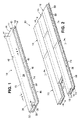
- FIG. 1 is a perspective view of a floor plank incorporating one embodiment of the present invention
- FIG. 2 is a perspective view of an assembly pattern thereof
- FIG. 3 is a sectional view taken on the line 3 - 3 of FIG. 2 ;
- FIG. 4 is a sectional view taken on the line 4 - 4 of FIG. 2 ;
- FIG. 5 is a sectional view thereof on a floor base
- FIG. 6 is a perspective view showing the flexibility characteristics of the floor plank
- FIG. 7 is a perspective view of a floor plank incorporating another embodiment of the invention.
- FIG. 8 is a perspective view of an assembly pattern thereof
- FIG. 9 is a sectional view taken on the line 9 - 9 of FIG. 8 ;
- FIG. 10 is a sectional view taken on the line 10 - 10 of FIG. 8 ;
- FIG. 11 is a sectional view thereof on a floor base
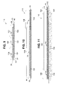
- FIGS. 12-14 are perspective views of a packaging system for the floor plank incorporating another embodiment of the invention, before, during and after installation in a floor plank;
- FIG. 15 is a plan view of the packaging system packaging device.
- FIG. 16 is a perspective view of a floor plank incorporating a further embodiment of the invention.
- a floor plank incorporating a preferred embodiment of the invention is generally indicated by the reference number 10 in FIG. 1 .
- the floor plank 10 is a laminate of a top layer 14 of flexible plastic sheet material, a middle layer 16 of flexible plastic sheet material and a bottom layer 18 of flexible foam material. All of the layers 14 , 16 and 18 are of identical polygonal size and shape, preferably rectangular.
- the top layer 14 and the middle layer 16 are preferably formed of a synthetic plastic material, preferably a vinyl plastic material such as polyvinyl chloride sheeting material.
- An upper surface 24 of the top layer 14 is provided with a design such as a synthetic wood grain design ( FIG. 6 ) that resembles natural wood.
- the bottom layer 18 is formed of a soft flexible foam material such as polyurethane foam.
- the middle plastic layer 16 and bottom foam layer 18 are laminated together such that they are coextensive and have a common periphery. However the top plastic layer 14 is laminated to the middle plastic layer 16 such that the top layer 14 is offset from the middle layer 16 .
- a long edge 26 ( FIG. 1 ) of the top layer 14 extends an offset amount “a” beyond a long edge 32 of the middle layer 16 and a short edge 34 of the top layer 14 extends an offset amount “a” beyond a short edge 40 of the middle layer 16 to define an offset L-shaped marginal section 42 of the top layer 14 .
- a long edge 46 ( FIG. 1 ) of the middle layer 16 extends an offset amount “a” beyond a long edge 48 of the top layer 14
- a short edge 50 of the middle layer 16 extends an offset amount “a” beyond a short edge 56 of the top layer 14 to define an offset L-shaped marginal section 58 of the middle layer 16 .
- the L-shaped marginal section 42 of the top layer 14 and the L-shaped marginal section 58 of the middle layer 16 are of identical size and shape.
- a suitable bonding or adhesive composition for laminating the top plastic layer 14 and middle plastic layer 16 together has the following components, the amounts of which are approximate:
- the bonding material for the layers 14 and 16 is provided on a lower surface 64 ( FIG. 3 ) of the top plastic layer 14 and on an upper surface 66 of the middle plastic layer 16 .
- the same bonding material applied to the lower surface 64 and the upper surface 66 for laminating top plastic layer 14 and the middle plastic layer 16 can also be used for laminating the bottom foam layer 18 to the middle plastic layer 16 .
- the L-shaped marginal section 42 has a downwardly directed adhesive surface 72 ( FIG. 1 ) that is part of the lower surface 64 ( FIG. 3 ) of the top layer 14 and the L-shaped marginal section 58 has an upwardly directed adhesive surface 74 ( FIG. 1 ) that is part of the upper surface 66 ( FIG. 3 ) of the middle layer 16 .
- the adhesive on the exposed adhesive surfaces 72 and 74 is the bonding material used for laminating the top plastic layer 14 and the middle plastic layer 16 together.
- a suitable size for the top layer 14 , the middle layer 16 and the bottom layer 18 can be for example, 6 inches by 48 inches.
- the thickness of the top layer 14 can be, for example, approximately 2.0 mm and the thickness of the middle layer 16 can be, for example, approximately 2.5 mm.
- the thickness of the bottom foam layer 18 can be, for example, approximately 3 mm.
- the marginal offset “a” can be, for example, approximately 3 ⁇ 4 of an inch. Larger offsets would be provided for larger panels.
- the floor plank 10 is sufficiently flexible as schematically indicated in FIG. 6 , to conform to typical variations in surface contour of a floor base 102 ( FIG. 5 ) upon which the floor plank 10 is laid.
- the flexible foam material of the bottom layer 18 is yieldable to small bumps and other imperfections in the floor base 102 generally referred to as surface irregularities.
- the bottom foam layer 18 thus enables the floor plank 10 to conform to such surface irregularities and lie flat on the floor base 102 .
- the downwardly directed adhesive surface 72 ( FIG. 1 ) of the L-shaped marginal section 42 of the top layer 14 is positioned to engage the upwardly directed adhesive surface 74 of the L-shaped marginal section 58 of the middle layer 16 to form the assembly 80 of the floor planks 10 as shown in FIG. 2 .
- one of the planks 10 can be angled at approximately 45 degrees (not shown) with respect to the floor base 102 and onto the corresponding upwardly facing adhesive surface 74 ( FIG. 1 ) of an adjacent floor plank 10 .
- the floor plank assembly pattern 80 ( FIG. 2 ) is but one example of numerous possible plank patterns known in the art.
- the floor planks 10 can be installed on the floor base 102 ( FIG. 5 ) without mastic or an adhesive coating on the floor base 102 , and without mastic or adhesive on an undersurface 88 ( FIG. 3 ) of the bottom foam layer 18 .
- the floor planks 10 can be placed on a dry floor base surface 102 for easy shifting to any selected position, thereby facilitating installation of the floor planks 10 in any desired pattern.
- floor planks 10 Preferably the installation of floor planks 10 should start in a corner of a room (not shown) and proceed outwardly therefrom.
- An expansion gap of 1 ⁇ 4 inch for example, from each wall is generally suitable for most installations.
- the expansion gap is usually covered by molding. It has also been found helpful to provide double faced tape on the first row of floor planks 10 to help maintain the first row in place during the positioning of adjacent floor planks 10 .
- the top layer 14 , the middle layer 16 and the bottom layer 18 of the floor plank 10 are provided with an overall thickness that enables the floor plank 10 to be easily cut with a utility knife, if trimming is needed. Ease of trimming the floor plank 10 and the mastic free placement of the planks 10 on a floor base 102 make it convenient for a do-it-yourselfer to install the floor planks 10 .
- FIG. 7 Another embodiment of the floor plank is generally indicated by the reference number 100 in FIG. 7 .
- the floor plank 100 is a laminate of the top layer 14 and the middle layer 16 of the floor plank 10 , with the bottom foam layer 18 being omitted.
- the layers 14 and 16 are laminated together with marginal offsets “a” as previously described with respect to the floor plank 10 .
- the floor plank 100 thus includes identical L-shaped marginal sections 42 and 58 with identical offsets “a”.
- a lower surface 104 of the layer 16 can be free of any mastic or adhesive covering and placed in direct contact with the floor base 102 .
- the floor base 102 can also remain free of any mastic or adhesive covering.
- the lower surface 104 ( FIGS. 7 and 8 ) of the layer 16 which contacts the floor base 102 ( FIG. 11 ) is yieldable to surface irregularities of the floor base 102 and thus enables the floor plank 100 to conform to such surface irregularities and lie flat on the floor base 102 , as shown in FIG. 11 .
- a packaging system for the floor plank is generally indicated by the reference number 120 in FIG. 12 .
- the packaging system 120 will be described in connection with the floor plank 10 but is equally applicable to the floor plank 100 .
- the packaging system 120 includes a one-piece packaging device 122 ( FIG. 15 ) preferably of generally rectangular shape and formed of any suitable known flexible release material such as release paper or releasable plastic that is of a paper thin gauge.
- a suitable release material is silicone coated paper or equivalent release material.
- the packaging device 122 ( FIG. 15 ) has a rectangular outer periphery defined by opposite long side portions 128 , 130 and opposite short side portions 136 and 138 .
- the packaging device 122 also has a rectangular inner periphery defined by opposite long side portions 144 , 146 and opposite short side portions 152 and 154 .
- the distance between the outer peripheral side portions 128 , 130 , 136 and 138 and the corresponding inner peripheral side portions 144 , 146 , 152 and 154 is approximately equivalent to the marginal offset “a” of the L-shaped marginal sections 42 and 58 .
- the length of the outer long sides 128 and 130 of the device 122 ( FIG. 15 ) is at least equal to the length of any of the long edges 26 , 32 , 46 and 48 ( FIG. 1 ) of the layers 14 and 16 plus the marginal offset “a” of the L-shaped marginal sections 42 and 58 .
- the length of the outer short sides 136 and 138 ( FIG. 15 ) of the device 122 is at least equal to the length of any of the short edges 34 , 40 , 50 and 56 ( FIG. 1 ) of the layers 14 and 16 plus the marginal offset “a” of the L-shaped marginal sections 42 and 58 .
- the length of the inner long sides 144 and 146 of the device 122 ( FIG. 15 ) is approximately equivalent to the length of any of the long edges 26 , 32 , 46 and 48 ( FIG. 1 ) of the layers 14 and 16 minus the marginal offset “a”.
- the length of the inner short sides 152 and 154 of the device 122 ( FIG. 15 ) is approximately equivalent to the length of any of the outer short edges 34 , 40 , 50 , and 56 ( FIG. 1 ) of the layers 14 , 16 and 18 minus the marginal offset “a”.
- plank 10 and the packaging device 122 The following reference identifications can be made for the plank 10 and the packaging device 122 ;
- the packaging device 122 is assembled to the floor plank 10 in the manner shown in FIGS. 12 , 13 and 14 .
- two intersecting sides 160 and 162 ( FIGS. 12 and 15 ) of the device 122 are placed against the downwardly exposed adhesive surface 72 ( FIGS. 1 and 12 ) of the L-shaped marginal section 42 as shown in FIG. 13
- the remaining two intersecting sides 168 , 170 ( FIGS. 12 and 15 ) of the packaging device 122 are placed against the upward exposed adhesive surface 74 ( FIG. 1 ) of the L-shaped marginal section 58 .
- the inner long side portion 144 of the device 122 is placed against the long edge 32 of the middle layer 16 and the inner short side portion 154 of the device 122 is placed against the short edge 40 of the middle layer 16 .
- the sides 160 and 162 of the device 122 can thus contact and cover the downwardly exposed adhesive surface 72 of the L-shaped marginal portion 42 , as shown in FIG. 13 .
- the intersecting sides 168 and 170 of the device 122 are moved forward and against the upwardly exposed adhesive surface 74 of the L-shaped marginal section 58 as shown in FIGS. 13 and 14 .
- the inner long side portion 146 of the device 122 ( FIG. 12 ) is thus placed against the long edge portion 48 of the top layer 14 and the inner short side portion 152 of the device 122 is placed against the short edge portion 56 of the top layer 14 .
- the device 122 can be stretched slightly, if needed, to accomplish the positioning of the sides 160 and 162 of the device 122 against the downwardly exposed adhesive surface 72 and the positioning of the sides 168 and 170 of the device 122 against the upwardly exposed adhesive surface 74 .
- the one piece packaging device 122 preferably of closed rectangular periphery, covers all the exposed adhesive surfaces of both L-shaped marginal sections 42 and 58 even though the panel 10 includes one L-shaped marginal section 42 with a downwardly exposed adhesive surface 72 ( FIG. 1 ) and the other L-shaped marginal section 58 has an upwardly exposed adhesive surface 74 .
- the packaging device 122 when installed on each of the planks 10 before such planks are ready for use permits the floor planks 10 to be stacked one on top of another (not shown) without one plank 10 adhering to another plank 10 .
- the planks 10 can be stacked for packaging or for display purposes.
- a further and preferred embodiment of the floor plank is generally indicated by the reference number 180 in FIG. 16 .
- the floor plank 180 includes all components of the floor plank 10 , with the same marginal offsets as previously described, plus an underlayer 182 of flexible fibrous sheet material sandwiched between the top layer 14 and the middle layer 16 .
- the underlayer 182 provides enhanced dimensional stability to the floor plank 180 .
- the top layer 14 and the underlayer 182 are coextensive and have a common periphery.
- the underlayer 182 is formed of a non-woven glass fiber material such as fiberglass, having a thickness of approximately 0.2 mm.
- floor plank 180 includes the identical L-shaped marginal sections 42 and 58 with identical offsets “a” as previously described for the floor plank 10 .
- the marginal section 42 has the downwardly exposed adhesive surface 72 on the underlayer 182 and the marginal section 58 has the upwardly exposed adhesive surface 74 on the middle layer 16 .
- the adhesive on the exposed surfaces 72 and 74 is the same adhesive used in the floor plank 10 to bond the top layer 14 to the middle layer 16 .
- the same adhesive is used to bond the underlayer 182 to the top layer 14 and to the middle layer 16 , and to bond the middle layer 16 to the bottom layer 18 .
- the floor plank 180 is installed on a floor in a manner similar to the previously described for the floor plank 10 .
Abstract
Description
-
- A=the length of any of the
long edges layers - B=the length of any of the
short edges layers - C=the length of any of the outer
long sides device 122 - D=the length of any of the outer
short sides device 122 - E=the length of any of the inner
long sides device 122 - F=the length of any of the inner
short sides device 122 - a=the marginal offset of the L-shaped
marginal portions
- A=the length of any of the
C=A+a
D=B+a
E=A−a
F=B−a
Claims (5)
Priority Applications (1)
| Application Number | Priority Date | Filing Date | Title |
|---|---|---|---|
| US11/545,834 US7322159B2 (en) | 2005-12-29 | 2006-10-11 | Floor plank |
Applications Claiming Priority (2)
| Application Number | Priority Date | Filing Date | Title |
|---|---|---|---|
| US11/321,015 US7155871B1 (en) | 2005-12-29 | 2005-12-29 | Floor plank |
| US11/545,834 US7322159B2 (en) | 2005-12-29 | 2006-10-11 | Floor plank |
Related Parent Applications (1)
| Application Number | Title | Priority Date | Filing Date |
|---|---|---|---|
| US11/321,015 Division US7155871B1 (en) | 2005-12-29 | 2005-12-29 | Floor plank |
Publications (2)
| Publication Number | Publication Date |
|---|---|
| US20070175137A1 US20070175137A1 (en) | 2007-08-02 |
| US7322159B2 true US7322159B2 (en) | 2008-01-29 |
Family
ID=37451471
Family Applications (2)
| Application Number | Title | Priority Date | Filing Date |
|---|---|---|---|
| US11/321,015 Active US7155871B1 (en) | 2005-12-29 | 2005-12-29 | Floor plank |
| US11/545,834 Active - Reinstated US7322159B2 (en) | 2005-12-29 | 2006-10-11 | Floor plank |
Family Applications Before (1)
| Application Number | Title | Priority Date | Filing Date |
|---|---|---|---|
| US11/321,015 Active US7155871B1 (en) | 2005-12-29 | 2005-12-29 | Floor plank |
Country Status (19)
| Country | Link |
|---|---|
| US (2) | US7155871B1 (en) |
| EP (1) | EP1803869B1 (en) |
| JP (1) | JP4680881B2 (en) |
| KR (1) | KR100865915B1 (en) |
| AR (1) | AR058353A1 (en) |
| AT (1) | ATE421012T1 (en) |
| AU (1) | AU2006201915B1 (en) |
| BR (1) | BRPI0605389A (en) |
| CA (1) | CA2545319C (en) |
| DE (2) | DE602006004835D1 (en) |
| DK (1) | DK1803869T3 (en) |
| ES (1) | ES2321547T3 (en) |
| FR (1) | FR2895759A1 (en) |
| MX (1) | MXPA06012067A (en) |
| NO (1) | NO20066035L (en) |
| PL (1) | PL1803869T3 (en) |
| PT (1) | PT1803869E (en) |
| TR (1) | TR200607462A1 (en) |
| TW (1) | TWI316982B (en) |
Cited By (17)
| Publication number | Priority date | Publication date | Assignee | Title |
|---|---|---|---|---|
| US20070163194A1 (en) * | 2005-12-29 | 2007-07-19 | Tru Woods Limited | Floor tile |
| US20080000172A1 (en) * | 2006-06-30 | 2008-01-03 | Gaztransport Et Technigaz | Prefabricated panel with protective film |
| US20080289277A1 (en) * | 2007-05-25 | 2008-11-27 | Tru Woods Limited | Floor member |
| US20100139095A1 (en) * | 2008-12-08 | 2010-06-10 | Barry Shannon Fuller | Method for producing engineered wood flooring and product |
| US20100319294A1 (en) * | 2009-06-22 | 2010-12-23 | Courey Stephen P | Tile Structure and Assembly for Covering Predetermined Surface |
| US20110042003A1 (en) * | 2009-08-21 | 2011-02-24 | Balmer Richard H | Method of making a floor panel |
| US20110042252A1 (en) * | 2009-08-21 | 2011-02-24 | Balmer Richard H | Packaging system for a floor panel |
| WO2011153940A1 (en) | 2010-06-09 | 2011-12-15 | Hong Kong Mei Li Sheng Flooring Co., Limited | Board and board assembly |
| US8171691B1 (en) * | 2011-03-03 | 2012-05-08 | Tower Ipco Company Limited | Floor member with cork substrate |
| US8268110B2 (en) | 2010-04-29 | 2012-09-18 | Advance Vinyl Floor Manufacturing Corp. | Method and apparatus for floor planks |
| USD668794S1 (en) * | 2009-04-16 | 2012-10-09 | Rene St-Cyr (1996) Inc. | Floor plank |
| US8745949B1 (en) | 2013-04-12 | 2014-06-10 | Chao Kang Pien | Method and apparatus for flooring |
| WO2014179437A1 (en) | 2013-05-02 | 2014-11-06 | Stone, Norman | Multi-purpose tile |
| US8950147B2 (en) * | 2011-08-22 | 2015-02-10 | Awi Licensing Company | Floor panel and floating floor system incorporating the same |
| US9181717B1 (en) * | 2010-10-07 | 2015-11-10 | Stagestep, Inc. | Transportable flooring kit and method for assembling the same |
| EP3141674A1 (en) | 2015-09-04 | 2017-03-15 | Tower Ipco Company Limited | Floor member with foam core |
| US10024065B2 (en) | 2009-03-27 | 2018-07-17 | Afi Licensing Llc | Floor panel and floating floor system incorporating the same |
Families Citing this family (52)
| Publication number | Priority date | Publication date | Assignee | Title |
|---|---|---|---|---|
| US7155871B1 (en) * | 2005-12-29 | 2007-01-02 | Tru Woods Limited | Floor plank |
| SE530653C2 (en) | 2006-01-12 | 2008-07-29 | Vaelinge Innovation Ab | Moisture-proof floor board and floor with an elastic surface layer including a decorative groove |
| US8728603B2 (en) | 2006-12-11 | 2014-05-20 | Ulrich Windmöller Consulting GmbH | Floor panel |
| DE102006058655B4 (en) * | 2006-12-11 | 2010-01-21 | Ulrich Windmöller Consulting GmbH | floor panel |
| CN101532331A (en) * | 2007-07-30 | 2009-09-16 | 诺瓦利斯股份有限公司 | Floor covering with interlocking design |
| CN201103225Y (en) * | 2007-08-02 | 2008-08-20 | 毛振基 | Plastic rubber floor board structure |
| KR200442721Y1 (en) * | 2007-09-07 | 2008-12-05 | 크레신산업 주식회사 | Floor Plank with Adhesive Portion Able to Adjust the Position |
| KR200442720Y1 (en) * | 2007-09-07 | 2008-12-05 | 크레신산업 주식회사 | Floor Plank with Adhesive Portion Able to Adjust the Position |
| CN101392590A (en) | 2007-09-18 | 2009-03-25 | 优尼卡澳大利亚有限公司 | Floor covering system |
| US9446564B2 (en) | 2009-03-03 | 2016-09-20 | Schneller Llc | Polyurethane based rigid flooring laminate |
| US20100269443A1 (en) * | 2009-04-23 | 2010-10-28 | Ziming Shen | Tongue-in-groove floor and wall panels using multiple bonded sheet construction |
| EP2233662A1 (en) | 2009-03-12 | 2010-09-29 | Jurgen Eberhard | Covering system for forming a floor covering |
| US8793959B2 (en) * | 2009-05-08 | 2014-08-05 | Novalis Holdings Limited | Overlap system for a flooring system |
| US20110030300A1 (en) * | 2009-08-10 | 2011-02-10 | Liu David C | Floor And Tile With Padding |
| US11725395B2 (en) | 2009-09-04 | 2023-08-15 | Välinge Innovation AB | Resilient floor |
| US8365499B2 (en) | 2009-09-04 | 2013-02-05 | Valinge Innovation Ab | Resilient floor |
| US8298650B2 (en) * | 2009-09-26 | 2012-10-30 | Gip International Limited | Hollow base decorative surface covering |
| US8833028B2 (en) | 2010-01-11 | 2014-09-16 | Valinge Innovation Ab | Floor covering with interlocking design |
| AT510089B1 (en) * | 2010-07-13 | 2012-09-15 | Tuechler Buehnen & Textiltechnik Gmbh | FLOORING |
| DE202010010621U1 (en) | 2010-07-24 | 2011-11-10 | Wolfgang Heinz | floor tile |
| KR101274852B1 (en) | 2010-08-23 | 2013-06-13 | (주)엘지하우시스 | Floor panel having adhesive applied sheet |
| US8512848B2 (en) | 2010-09-16 | 2013-08-20 | Gip International Limited | Adhesiveless decorative floor tile |
| US8703275B2 (en) | 2011-06-21 | 2014-04-22 | Gip International Limited | Adhesiveless decorative floor tile |
| US8191328B1 (en) * | 2011-02-04 | 2012-06-05 | Liu David C | Hardwood flooring with sliding locking mechanism |
| US20120240506A1 (en) | 2011-02-08 | 2012-09-27 | Sunstate Import/Export, Inc. | Self Locking Flooring Panels |
| EP2522793A1 (en) * | 2011-05-11 | 2012-11-14 | Vinyl Tech Enterprise Co., LTD. | Composite floor |
| DK3115161T3 (en) | 2011-08-29 | 2020-01-27 | Ceraloc Innovation Ab | FLOOR PANEL MECHANICAL LOCKING SYSTEM |
| CN102352684A (en) | 2011-09-05 | 2012-02-15 | 张家港市易华塑料有限公司 | Floor |
| KR101429336B1 (en) * | 2012-03-02 | 2014-08-11 | (주)엘지하우시스 | Floor panel having adhesive applied sheet |
| US9156233B2 (en) | 2012-10-22 | 2015-10-13 | Us Floors, Inc. | Engineered waterproof flooring and wall covering planks |
| EA201992325A1 (en) | 2013-03-25 | 2020-05-31 | Велинге Инновейшн Аб | FLOOR PANELS EQUIPPED WITH MECHANICAL FIXING SYSTEM AND METHOD FOR PRODUCING SUCH FIXING SYSTEM |
| US9643377B2 (en) | 2013-05-02 | 2017-05-09 | Tower Ipco Company Limited | Floor plank with foam core |
| CN103306459A (en) * | 2013-06-06 | 2013-09-18 | 惠东伟康橡塑制品有限公司 | PVC (Polyvinyl Chloride) floor with self-bonding structure |
| PL3039195T3 (en) | 2013-09-16 | 2019-07-31 | Best Woods Inc. | Surface covering connection joints |
| EP2894276A1 (en) | 2014-01-10 | 2015-07-15 | Sekisui Alveo AG | Interlocking polymer foam floor underlay element |
| CN115559492A (en) | 2014-07-16 | 2023-01-03 | 瓦林格创新股份有限公司 | Method for producing thermoplastic wear resistant foil |
| HUE061045T2 (en) | 2014-08-29 | 2023-05-28 | Vaelinge Innovation Ab | Vertical joint system for a surface covering panel |
| JP6322550B2 (en) * | 2014-10-31 | 2018-05-09 | 株式会社 五感 | Flooring structure |
| EP3390744A4 (en) | 2015-12-17 | 2019-07-31 | Välinge Innovation AB | A method for producing a mechanical locking system for panels |
| US10501943B1 (en) * | 2016-02-19 | 2019-12-10 | Custom Finish Wood Flooring Llc | Systems and methods for installing flooring |
| CN106065702A (en) * | 2016-06-29 | 2016-11-02 | 中建海峡建设发展有限公司 | A kind of splice floor tile and the preparation technology of this splicing floor tile and paving technique |
| MX2019003403A (en) | 2016-09-30 | 2019-05-30 | Vaelinge Innovation Ab | Set of panels assembled by vertical displacement and locked together in the vertical and horizontal direction. |
| WO2018089225A1 (en) * | 2016-11-08 | 2018-05-17 | Mannington Mills, Inc. | Adhesive-backed flooring panel, system, and method |
| TW201842264A (en) | 2017-04-18 | 2018-12-01 | 英商英威達紡織(英國)有限公司 | Easy to install ceramic or stone tile product |
| CA3076229A1 (en) * | 2017-09-20 | 2019-03-28 | Louisiana-Pacific Corporation | Integrated joint sealing system |
| EA039273B1 (en) | 2018-01-09 | 2021-12-27 | Велинге Инновейшн Аб | Set of panels |
| CN109252666A (en) * | 2018-08-27 | 2019-01-22 | 芜湖市黄山松工业地坪新材料有限公司 | A kind of terrace construction technique |
| CN110306797A (en) * | 2019-06-05 | 2019-10-08 | 成都建工工业化建筑有限公司 | A kind of " finishing process of the metope of assembled architecture band finishing |
| US11339576B2 (en) * | 2019-09-17 | 2022-05-24 | Daltile Corporation | Floor element for forming a floor covering and a floor covering |
| KR20220136366A (en) * | 2020-01-09 | 2022-10-07 | 아이4에프 라이센싱 엔뷔 | Adhesive decorative floor covering system |
| DE102020101062B4 (en) | 2020-01-17 | 2021-08-12 | Lang Technik Gmbh | Workpiece clamping device with coupling body between clamping body and threaded spindle |
| CN115038848A (en) * | 2020-02-07 | 2022-09-09 | 阿姆斯特郎世界工业公司 | Sound attenuating building panel |
Citations (40)
| Publication number | Priority date | Publication date | Assignee | Title |
|---|---|---|---|---|
| US1978075A (en) | 1931-07-13 | 1934-10-23 | Josephine M Butterworth | Wood block flooring |
| US2189218A (en) | 1937-12-06 | 1940-02-06 | Celotex Corp | Tiling |
| US2284705A (en) * | 1940-05-03 | 1942-06-02 | James N Wickersham | Shingle |
| US2390697A (en) * | 1942-07-04 | 1945-12-11 | Eason Sidney Lanier | Roofing or surfacing material |
| US2914815A (en) | 1955-08-17 | 1959-12-01 | Alexander Verna Cook | Interlocked flooring and method |
| US3247638A (en) | 1963-05-22 | 1966-04-26 | James W Fair | Interlocking tile carpet |
| US3434259A (en) * | 1966-06-03 | 1969-03-25 | Johns Manville | Roofing shingle |
| US3554850A (en) | 1966-10-20 | 1971-01-12 | Erich Kuhle | Laminated floor covering and method of making same |
| US3657852A (en) | 1969-09-15 | 1972-04-25 | Walter J Worthington | Floor tiles |
| US3859000A (en) | 1972-03-30 | 1975-01-07 | Reynolds Metals Co | Road construction and panel for making same |
| US3988187A (en) | 1973-02-06 | 1976-10-26 | Atlantic Richfield Company | Method of laying floor tile |
| US4090338A (en) | 1976-12-13 | 1978-05-23 | B 3 L | Parquet floor elements and parquet floor composed of such elements |
| US4426820A (en) | 1979-04-24 | 1984-01-24 | Heinz Terbrack | Panel for a composite surface and a method of assembling same |
| US4644720A (en) | 1984-11-01 | 1987-02-24 | Schneider Raymond H | Hardwood flooring system |
| US5111630A (en) | 1987-12-28 | 1992-05-12 | C-Tec, Inc. | Access floor panel with peripheral trim |
| US5179812A (en) | 1991-05-13 | 1993-01-19 | Flourlock (Uk) Limited | Flooring product |
| US5304272A (en) * | 1991-08-12 | 1994-04-19 | American Biltrite, Inc. | Method for manufacture of process printed surface covering |
| US5404686A (en) | 1992-05-11 | 1995-04-11 | Esposito; Chris | Construction arrangement including multiple panels provided with interlocking edges and related methods |
| US5417026A (en) | 1993-05-03 | 1995-05-23 | Brumfield; James W. | Corrugated building components |
| US5711128A (en) | 1994-06-06 | 1998-01-27 | Oy Shippax Ltd. | Method for joining wallboards together and a novel wall element |
| US5837375A (en) * | 1993-09-03 | 1998-11-17 | Rexham Graphics Incorporated | Ink jet imaging process and recording element for use therein |
| US5916654A (en) * | 1997-08-27 | 1999-06-29 | Phillips; Aaron R. | Method and apparatus for preventing adhesion of multi-part release liners |
| US6029416A (en) | 1995-01-30 | 2000-02-29 | Golvabia Ab | Jointing system |
| US6119423A (en) | 1998-09-14 | 2000-09-19 | Costantino; John | Apparatus and method for installing hardwood floors |
| US6156402A (en) | 1997-08-04 | 2000-12-05 | Triangle Pacific Corp. | Wooden flooring strip with enhanced flexibility and straightness |
| US6235365B1 (en) * | 1998-12-18 | 2001-05-22 | W. R. Grace & Co.-Conn. | Waterproofing membrane having release sheet cutting system |
| DE20214720U1 (en) | 2002-09-24 | 2002-11-28 | Winter Thomas | Loose, elastic floor panels |
| US6511257B1 (en) * | 2000-05-31 | 2003-01-28 | Ols Consulting Services, Inc. | Interlocking mat system for construction of load supporting surfaces |
| CA2468532A1 (en) | 2001-11-28 | 2003-06-05 | James Hardie Research Pty Limited | Trough-edge building panel and method of manufacture |
| US6591568B1 (en) | 2000-03-31 | 2003-07-15 | Pergo (Europe) Ab | Flooring material |
| US6601359B2 (en) | 2001-01-26 | 2003-08-05 | Pergo (Europe) Ab | Flooring panel or wall panel |
| US6647690B1 (en) | 1999-02-10 | 2003-11-18 | Pergo (Europe) Ab | Flooring material, comprising board shaped floor elements which are intended to be joined vertically |
| US6656557B2 (en) * | 1998-09-25 | 2003-12-02 | Tamko Roofing Products, Inc. | Waterproofing membrane and method of manufacture |
| US6659097B1 (en) * | 2000-09-22 | 2003-12-09 | Daniel J. Houston | Custom manufacture of tiles for use with preexisting mass-manufactured tiles |
| US6691480B2 (en) | 2002-05-03 | 2004-02-17 | Faus Group | Embossed-in-register panel system |
| US6751917B2 (en) | 2002-04-10 | 2004-06-22 | Chen-Chi Mao | Floor tile structure without adhesive coating at the bottom |
| US6769218B2 (en) | 2001-01-12 | 2004-08-03 | Valinge Aluminium Ab | Floorboard and locking system therefor |
| US6786019B2 (en) | 2000-06-13 | 2004-09-07 | Flooring Industries, Ltd. | Floor covering |
| US6794001B2 (en) | 2002-07-25 | 2004-09-21 | Mannington Mills, Inc. | Flooring with a 2-part adhesive |
| US6823638B2 (en) | 2001-06-27 | 2004-11-30 | Pergo (Europe) Ab | High friction joint, and interlocking joints for forming a generally planar surface, and method of assembling the same |
Family Cites Families (17)
| Publication number | Priority date | Publication date | Assignee | Title |
|---|---|---|---|---|
| US3247368A (en) * | 1963-07-16 | 1966-04-19 | Arnold Company Inc | Fluorescent lighting fixture |
| DE1914705A1 (en) | 1969-03-22 | 1970-10-01 | Walterscheid Karl Joseph | Lapped tiled flooring |
| FR2041603A5 (en) * | 1969-04-30 | 1971-01-29 | Couquet Pierre | |
| JPS5249519U (en) * | 1975-10-07 | 1977-04-08 | ||
| DE3031036A1 (en) | 1980-08-16 | 1982-03-04 | Roth Werke Gmbh, 3563 Dautphetal | Thermally insulating panel to underfloor heating - has edge laps coated with adhesive to bond to adjacent panel |
| JPS63247466A (en) * | 1987-04-30 | 1988-10-14 | 朝日ウッドテック株式会社 | Execution of wooden decorative floor |
| DK158336C (en) * | 1987-09-22 | 1990-10-01 | Coloplast As | CONNECTOR MATERIALS FOR THE TREATMENT OF WOUNDS AND TEMPLES FOR USE IN MANUFACTURING THEREOF |
| JPH07229280A (en) * | 1994-02-16 | 1995-08-29 | Hitachi Gomme Kako Kk | Double floor |
| JPH07300808A (en) * | 1994-05-09 | 1995-11-14 | Sekisui Jushi Co Ltd | Plastic-made floor board |
| KR200142011Y1 (en) * | 1996-11-18 | 1999-06-01 | 장용재 | Functional floor plate |
| AU3925899A (en) * | 1998-03-26 | 1999-10-18 | Casa Da Vinci Bodensysteme Gmbh & Co Kg | Floor tile |
| JP2001159229A (en) * | 1999-12-02 | 2001-06-12 | Sekisui Chem Co Ltd | Heating and sound insulation floor member and construction method therefor |
| KR200231812Y1 (en) * | 2001-02-01 | 2001-07-19 | 고덕기 | Cushion broad material |
| DE20108723U1 (en) | 2001-05-25 | 2002-03-14 | Winter Thomas | Loose, elastic floor panels for grouting |
| JP2004116038A (en) * | 2002-09-24 | 2004-04-15 | Toppan Printing Co Ltd | Flooring |
| KR200359803Y1 (en) | 2004-05-12 | 2004-08-21 | 조성태 | Assembling flooring member |
| US7155871B1 (en) * | 2005-12-29 | 2007-01-02 | Tru Woods Limited | Floor plank |
-
2005
- 2005-12-29 US US11/321,015 patent/US7155871B1/en active Active
-
2006
- 2006-04-28 CA CA002545319A patent/CA2545319C/en not_active Expired - Fee Related
- 2006-05-08 AU AU2006201915A patent/AU2006201915B1/en not_active Ceased
- 2006-05-19 TW TW095117899A patent/TWI316982B/en not_active IP Right Cessation
- 2006-10-11 US US11/545,834 patent/US7322159B2/en active Active - Reinstated
- 2006-10-19 MX MXPA06012067A patent/MXPA06012067A/en active IP Right Grant
- 2006-12-14 AT AT06126194T patent/ATE421012T1/en active
- 2006-12-14 AR ARP060105529A patent/AR058353A1/en active IP Right Grant
- 2006-12-14 PL PL06126194T patent/PL1803869T3/en unknown
- 2006-12-14 EP EP06126194A patent/EP1803869B1/en not_active Not-in-force
- 2006-12-14 DE DE602006004835T patent/DE602006004835D1/en active Active
- 2006-12-14 PT PT06126194T patent/PT1803869E/en unknown
- 2006-12-14 ES ES06126194T patent/ES2321547T3/en active Active
- 2006-12-14 DK DK06126194T patent/DK1803869T3/en active
- 2006-12-18 KR KR1020060129146A patent/KR100865915B1/en not_active IP Right Cessation
- 2006-12-22 JP JP2006346225A patent/JP4680881B2/en not_active Expired - Fee Related
- 2006-12-26 TR TR2006/07462A patent/TR200607462A1/en unknown
- 2006-12-27 NO NO20066035A patent/NO20066035L/en not_active Application Discontinuation
- 2006-12-27 DE DE102006062318A patent/DE102006062318A1/en not_active Withdrawn
- 2006-12-28 BR BRPI0605389-0A patent/BRPI0605389A/en not_active IP Right Cessation
- 2006-12-29 FR FR0611522A patent/FR2895759A1/en active Pending
Patent Citations (42)
| Publication number | Priority date | Publication date | Assignee | Title |
|---|---|---|---|---|
| US1978075A (en) | 1931-07-13 | 1934-10-23 | Josephine M Butterworth | Wood block flooring |
| US2189218A (en) | 1937-12-06 | 1940-02-06 | Celotex Corp | Tiling |
| US2284705A (en) * | 1940-05-03 | 1942-06-02 | James N Wickersham | Shingle |
| US2390697A (en) * | 1942-07-04 | 1945-12-11 | Eason Sidney Lanier | Roofing or surfacing material |
| US2914815A (en) | 1955-08-17 | 1959-12-01 | Alexander Verna Cook | Interlocked flooring and method |
| US3247638A (en) | 1963-05-22 | 1966-04-26 | James W Fair | Interlocking tile carpet |
| US3434259A (en) * | 1966-06-03 | 1969-03-25 | Johns Manville | Roofing shingle |
| US3554850A (en) | 1966-10-20 | 1971-01-12 | Erich Kuhle | Laminated floor covering and method of making same |
| US3657852A (en) | 1969-09-15 | 1972-04-25 | Walter J Worthington | Floor tiles |
| US3859000A (en) | 1972-03-30 | 1975-01-07 | Reynolds Metals Co | Road construction and panel for making same |
| US3988187A (en) | 1973-02-06 | 1976-10-26 | Atlantic Richfield Company | Method of laying floor tile |
| US4090338A (en) | 1976-12-13 | 1978-05-23 | B 3 L | Parquet floor elements and parquet floor composed of such elements |
| US4426820A (en) | 1979-04-24 | 1984-01-24 | Heinz Terbrack | Panel for a composite surface and a method of assembling same |
| US4644720A (en) | 1984-11-01 | 1987-02-24 | Schneider Raymond H | Hardwood flooring system |
| US5111630A (en) | 1987-12-28 | 1992-05-12 | C-Tec, Inc. | Access floor panel with peripheral trim |
| US5179812A (en) | 1991-05-13 | 1993-01-19 | Flourlock (Uk) Limited | Flooring product |
| US5304272A (en) * | 1991-08-12 | 1994-04-19 | American Biltrite, Inc. | Method for manufacture of process printed surface covering |
| US5404686A (en) | 1992-05-11 | 1995-04-11 | Esposito; Chris | Construction arrangement including multiple panels provided with interlocking edges and related methods |
| US5417026A (en) | 1993-05-03 | 1995-05-23 | Brumfield; James W. | Corrugated building components |
| US5837375A (en) * | 1993-09-03 | 1998-11-17 | Rexham Graphics Incorporated | Ink jet imaging process and recording element for use therein |
| US5711128A (en) | 1994-06-06 | 1998-01-27 | Oy Shippax Ltd. | Method for joining wallboards together and a novel wall element |
| US6029416A (en) | 1995-01-30 | 2000-02-29 | Golvabia Ab | Jointing system |
| US6156402A (en) | 1997-08-04 | 2000-12-05 | Triangle Pacific Corp. | Wooden flooring strip with enhanced flexibility and straightness |
| US5916654A (en) * | 1997-08-27 | 1999-06-29 | Phillips; Aaron R. | Method and apparatus for preventing adhesion of multi-part release liners |
| US6119423A (en) | 1998-09-14 | 2000-09-19 | Costantino; John | Apparatus and method for installing hardwood floors |
| US6656557B2 (en) * | 1998-09-25 | 2003-12-02 | Tamko Roofing Products, Inc. | Waterproofing membrane and method of manufacture |
| US6235365B1 (en) * | 1998-12-18 | 2001-05-22 | W. R. Grace & Co.-Conn. | Waterproofing membrane having release sheet cutting system |
| US6647690B1 (en) | 1999-02-10 | 2003-11-18 | Pergo (Europe) Ab | Flooring material, comprising board shaped floor elements which are intended to be joined vertically |
| US6591568B1 (en) | 2000-03-31 | 2003-07-15 | Pergo (Europe) Ab | Flooring material |
| US6695527B2 (en) * | 2000-05-31 | 2004-02-24 | Ols Consulting Services, Inc. | Interlocking mat system for construction of load supporting surfaces |
| US6511257B1 (en) * | 2000-05-31 | 2003-01-28 | Ols Consulting Services, Inc. | Interlocking mat system for construction of load supporting surfaces |
| US6786019B2 (en) | 2000-06-13 | 2004-09-07 | Flooring Industries, Ltd. | Floor covering |
| US6659097B1 (en) * | 2000-09-22 | 2003-12-09 | Daniel J. Houston | Custom manufacture of tiles for use with preexisting mass-manufactured tiles |
| US6769218B2 (en) | 2001-01-12 | 2004-08-03 | Valinge Aluminium Ab | Floorboard and locking system therefor |
| US6601359B2 (en) | 2001-01-26 | 2003-08-05 | Pergo (Europe) Ab | Flooring panel or wall panel |
| US6823638B2 (en) | 2001-06-27 | 2004-11-30 | Pergo (Europe) Ab | High friction joint, and interlocking joints for forming a generally planar surface, and method of assembling the same |
| CA2468532A1 (en) | 2001-11-28 | 2003-06-05 | James Hardie Research Pty Limited | Trough-edge building panel and method of manufacture |
| US6751917B2 (en) | 2002-04-10 | 2004-06-22 | Chen-Chi Mao | Floor tile structure without adhesive coating at the bottom |
| US6691480B2 (en) | 2002-05-03 | 2004-02-17 | Faus Group | Embossed-in-register panel system |
| US6794001B2 (en) | 2002-07-25 | 2004-09-21 | Mannington Mills, Inc. | Flooring with a 2-part adhesive |
| DE20214720U1 (en) | 2002-09-24 | 2002-11-28 | Winter Thomas | Loose, elastic floor panels |
| DE20307987U1 (en) | 2002-09-24 | 2004-09-23 | Winter, Thomas | Floor plate comprises a carrier plate and a decorative plate joined to one another by a permanently active glue covering the entire surface of the carrier plate |
Cited By (29)
| Publication number | Priority date | Publication date | Assignee | Title |
|---|---|---|---|---|
| US7458191B2 (en) * | 2005-12-29 | 2008-12-02 | Tru Woods Limited | Floor tile |
| US20070163194A1 (en) * | 2005-12-29 | 2007-07-19 | Tru Woods Limited | Floor tile |
| US7934353B2 (en) * | 2006-06-30 | 2011-05-03 | Gaztransport Et Technigaz | Prefabricated panel with protective film |
| US20080000172A1 (en) * | 2006-06-30 | 2008-01-03 | Gaztransport Et Technigaz | Prefabricated panel with protective film |
| US20080289277A1 (en) * | 2007-05-25 | 2008-11-27 | Tru Woods Limited | Floor member |
| US7685790B2 (en) * | 2007-05-25 | 2010-03-30 | Tru Woods Limited | Floor member |
| US20100170179A1 (en) * | 2007-05-25 | 2010-07-08 | Tru Woods Limited | Floor member |
| US8250824B2 (en) | 2007-05-25 | 2012-08-28 | Tower IPCO Company | Floor member |
| US20100139095A1 (en) * | 2008-12-08 | 2010-06-10 | Barry Shannon Fuller | Method for producing engineered wood flooring and product |
| US8347506B2 (en) * | 2008-12-08 | 2013-01-08 | Wolf, Incorporated | Method for producing engineered wood flooring and product |
| US10024065B2 (en) | 2009-03-27 | 2018-07-17 | Afi Licensing Llc | Floor panel and floating floor system incorporating the same |
| USD668794S1 (en) * | 2009-04-16 | 2012-10-09 | Rene St-Cyr (1996) Inc. | Floor plank |
| US20100319294A1 (en) * | 2009-06-22 | 2010-12-23 | Courey Stephen P | Tile Structure and Assembly for Covering Predetermined Surface |
| US20110042252A1 (en) * | 2009-08-21 | 2011-02-24 | Balmer Richard H | Packaging system for a floor panel |
| US20110042003A1 (en) * | 2009-08-21 | 2011-02-24 | Balmer Richard H | Method of making a floor panel |
| US8894794B2 (en) | 2009-08-21 | 2014-11-25 | Awi Licensing Company | Method of making a floor panel |
| US8720684B2 (en) | 2009-08-21 | 2014-05-13 | Awi Licensing Company | Packaging system for a floor panel |
| US8268110B2 (en) | 2010-04-29 | 2012-09-18 | Advance Vinyl Floor Manufacturing Corp. | Method and apparatus for floor planks |
| WO2011153940A1 (en) | 2010-06-09 | 2011-12-15 | Hong Kong Mei Li Sheng Flooring Co., Limited | Board and board assembly |
| US8726603B2 (en) | 2010-06-09 | 2014-05-20 | Hong Kong Mei Li Sheng Flooring Co., Limited | Board assembly |
| US9181717B1 (en) * | 2010-10-07 | 2015-11-10 | Stagestep, Inc. | Transportable flooring kit and method for assembling the same |
| WO2012117388A1 (en) | 2011-03-03 | 2012-09-07 | Tower Ipco Company Limited | Floor plank with cork substrate |
| CN103403280A (en) * | 2011-03-03 | 2013-11-20 | 托维尔伊普克有限公司 | Floor plank with cork substrate |
| US8171691B1 (en) * | 2011-03-03 | 2012-05-08 | Tower Ipco Company Limited | Floor member with cork substrate |
| US8950147B2 (en) * | 2011-08-22 | 2015-02-10 | Awi Licensing Company | Floor panel and floating floor system incorporating the same |
| US9611654B2 (en) | 2011-08-22 | 2017-04-04 | Afi Licensing Llc | Floor panel and floating floor system incorporating the same |
| US8745949B1 (en) | 2013-04-12 | 2014-06-10 | Chao Kang Pien | Method and apparatus for flooring |
| WO2014179437A1 (en) | 2013-05-02 | 2014-11-06 | Stone, Norman | Multi-purpose tile |
| EP3141674A1 (en) | 2015-09-04 | 2017-03-15 | Tower Ipco Company Limited | Floor member with foam core |
Also Published As
| Publication number | Publication date |
|---|---|
| PT1803869E (en) | 2009-04-14 |
| TR200607462A1 (en) | 2007-07-23 |
| ES2321547T3 (en) | 2009-06-08 |
| KR100865915B1 (en) | 2008-10-29 |
| MXPA06012067A (en) | 2007-07-04 |
| EP1803869B1 (en) | 2009-01-14 |
| US20070175137A1 (en) | 2007-08-02 |
| BRPI0605389A (en) | 2007-10-16 |
| CA2545319A1 (en) | 2006-11-20 |
| TWI316982B (en) | 2009-11-11 |
| FR2895759A1 (en) | 2007-07-06 |
| ATE421012T1 (en) | 2009-01-15 |
| DK1803869T3 (en) | 2009-03-09 |
| AR058353A1 (en) | 2008-01-30 |
| EP1803869A1 (en) | 2007-07-04 |
| NO20066035L (en) | 2007-07-02 |
| KR20070072369A (en) | 2007-07-04 |
| DE602006004835D1 (en) | 2009-03-05 |
| CA2545319C (en) | 2007-09-11 |
| JP4680881B2 (en) | 2011-05-11 |
| AU2006201915B1 (en) | 2007-05-17 |
| US7155871B1 (en) | 2007-01-02 |
| DE102006062318A1 (en) | 2007-07-12 |
| TW200724760A (en) | 2007-07-01 |
| PL1803869T3 (en) | 2009-06-30 |
| JP2007182750A (en) | 2007-07-19 |
Similar Documents
| Publication | Publication Date | Title |
|---|---|---|
| US7322159B2 (en) | Floor plank | |
| US7458191B2 (en) | Floor tile | |
| KR100387661B1 (en) | System for joining building boards | |
| US7930862B2 (en) | Floorboards having a resilent surface layer with a decorative groove | |
| US20110030300A1 (en) | Floor And Tile With Padding | |
| US20050229520A1 (en) | Studded plate with fold line | |
| US20100281810A1 (en) | Overlap System For A Flooring System | |
| CA2568978C (en) | Floor tile | |
| US20030205018A1 (en) | Metal faced tile | |
| JPH0133702Y2 (en) | ||
| CN100572721C (en) | Wood floor bolck and packing method thereof | |
| US20210230884A1 (en) | Flooring underlayment system | |
| EP0138846B1 (en) | Lining material for covering floors, walls, ceilings and columns | |
| JP3551287B2 (en) | Insulated flooring | |
| JP2003286769A (en) | Floor structure and execution method therefor | |
| JP2000356030A (en) | Wooden decorative flooring | |
| US20110209427A1 (en) | Floor Tile | |
| JPH02104860A (en) | Construction of floor board | |
| JPH066580U (en) | Veneer | |
| CA2220185A1 (en) | Tiled surface covering | |
| WO2012083362A1 (en) | Floor covering system | |
| GB2374093A (en) | Beading for edge of hardwood floor | |
| CA2695033A1 (en) | Floor tile |
Legal Events
| Date | Code | Title | Description |
|---|---|---|---|
| AS | Assignment |
Owner name: METROFLOR CORP, CONNECTICUT Free format text: NUNC PRO TUNC ASSIGNMENT;ASSIGNOR:TRU WOODS LIMITED;REEL/FRAME:021590/0675 Effective date: 20080901 |
|
| AS | Assignment |
Owner name: TRU WOODS LIMITED,HONG KONG Free format text: ASSIGNMENT OF ASSIGNORS INTEREST;ASSIGNOR:METROFLOR CORPORATION;REEL/FRAME:024380/0756 Effective date: 20100512 |
|
| AS | Assignment |
Owner name: TOWER IPCO COMPANY LIMITED, IRELAND Free format text: ASSIGNMENT OF ASSIGNORS INTEREST;ASSIGNOR:TRU WOODS LIMITED;REEL/FRAME:026235/0383 Effective date: 20110130 |
|
| FPAY | Fee payment |
Year of fee payment: 4 |
|
| REMI | Maintenance fee reminder mailed | ||
| LAPS | Lapse for failure to pay maintenance fees | ||
| FP | Lapsed due to failure to pay maintenance fee |
Effective date: 20160129 |
|
| AS | Assignment |
Owner name: TRU WOODS LIMITED, HONG KONG Free format text: ASSIGNMENT OF ASSIGNORS INTEREST;ASSIGNOR:TRU WOODS LIMITED;REEL/FRAME:043929/0250 Effective date: 20110120 |
|
| AS | Assignment |
Owner name: TRU WOODS LIMITED, HONG KONG Free format text: ASSIGNMENT OF ASSIGNORS INTEREST;ASSIGNOR:TOWER IPCO COMPANY LIMITED;REEL/FRAME:044348/0690 Effective date: 20171129 Owner name: ZHANGJIAGANG ELEGANT HOME-TECH CO., LTD, CHINA Free format text: ASSIGNMENT OF ASSIGNORS INTEREST;ASSIGNOR:TRU WOODS LIMITED;REEL/FRAME:044349/0090 Effective date: 20171201 |
|
| FEPP | Fee payment procedure |
Free format text: PETITION RELATED TO MAINTENANCE FEES FILED (ORIGINAL EVENT CODE: PMFP) |
|
| PRDP | Patent reinstated due to the acceptance of a late maintenance fee |
Effective date: 20181108 |
|
| FEPP | Fee payment procedure |
Free format text: SURCHARGE, PETITION TO ACCEPT PYMT AFTER EXP, UNINTENTIONAL (ORIGINAL EVENT CODE: M1558); ENTITY STATUS OF PATENT OWNER: LARGE ENTITY |
|
| MAFP | Maintenance fee payment |
Free format text: PAYMENT OF MAINTENANCE FEE, 8TH YEAR, LARGE ENTITY (ORIGINAL EVENT CODE: M1552); ENTITY STATUS OF PATENT OWNER: LARGE ENTITY Year of fee payment: 8 |
|
| FEPP | Fee payment procedure |
Free format text: PETITION RELATED TO MAINTENANCE FEES GRANTED (ORIGINAL EVENT CODE: PMFG); ENTITY STATUS OF PATENT OWNER: LARGE ENTITY |
|
| STCF | Information on status: patent grant |
Free format text: PATENTED CASE |
|
| MAFP | Maintenance fee payment |
Free format text: PAYMENT OF MAINTENANCE FEE, 12TH YEAR, LARGE ENTITY (ORIGINAL EVENT CODE: M1553); ENTITY STATUS OF PATENT OWNER: LARGE ENTITY Year of fee payment: 12 |