US8955268B2 - Modular tile with controlled deflection - Google Patents
Modular tile with controlled deflection Download PDFInfo
- Publication number
- US8955268B2 US8955268B2 US14/090,845 US201314090845A US8955268B2 US 8955268 B2 US8955268 B2 US 8955268B2 US 201314090845 A US201314090845 A US 201314090845A US 8955268 B2 US8955268 B2 US 8955268B2
- Authority
- US
- United States
- Prior art keywords
- tile
- post structures
- floor
- structures
- primary
- Prior art date
- Legal status (The legal status is an assumption and is not a legal conclusion. Google has not performed a legal analysis and makes no representation as to the accuracy of the status listed.)
- Active
Links
Images


Classifications
-
- E—FIXED CONSTRUCTIONS
- E04—BUILDING
- E04F—FINISHING WORK ON BUILDINGS, e.g. STAIRS, FLOORS
- E04F15/00—Flooring
- E04F15/22—Resiliently-mounted floors, e.g. sprung floors
- E04F15/225—Shock absorber members therefor
-
- E—FIXED CONSTRUCTIONS
- E01—CONSTRUCTION OF ROADS, RAILWAYS, OR BRIDGES
- E01C—CONSTRUCTION OF, OR SURFACES FOR, ROADS, SPORTS GROUNDS, OR THE LIKE; MACHINES OR AUXILIARY TOOLS FOR CONSTRUCTION OR REPAIR
- E01C13/00—Pavings or foundations specially adapted for playgrounds or sports grounds; Drainage, irrigation or heating of sports grounds
- E01C13/04—Pavings made of prefabricated single units
- E01C13/045—Pavings made of prefabricated single units the prefabricated single units consisting of or including bitumen, rubber or plastics
-
- E—FIXED CONSTRUCTIONS
- E01—CONSTRUCTION OF ROADS, RAILWAYS, OR BRIDGES
- E01C—CONSTRUCTION OF, OR SURFACES FOR, ROADS, SPORTS GROUNDS, OR THE LIKE; MACHINES OR AUXILIARY TOOLS FOR CONSTRUCTION OR REPAIR
- E01C5/00—Pavings made of prefabricated single units
- E01C5/20—Pavings made of prefabricated single units made of units of plastics, e.g. concrete with plastics, linoleum
-
- E—FIXED CONSTRUCTIONS
- E04—BUILDING
- E04B—GENERAL BUILDING CONSTRUCTIONS; WALLS, e.g. PARTITIONS; ROOFS; FLOORS; CEILINGS; INSULATION OR OTHER PROTECTION OF BUILDINGS
- E04B5/00—Floors; Floor construction with regard to insulation; Connections specially adapted therefor
- E04B5/43—Floor structures of extraordinary design; Features relating to the elastic stability; Floor structures specially designed for resting on columns only, e.g. mushroom floors
-
- E—FIXED CONSTRUCTIONS
- E04—BUILDING
- E04F—FINISHING WORK ON BUILDINGS, e.g. STAIRS, FLOORS
- E04F15/00—Flooring
- E04F15/02—Flooring or floor layers composed of a number of similar elements
- E04F15/10—Flooring or floor layers composed of a number of similar elements of other materials, e.g. fibrous or chipped materials, organic plastics, magnesite tiles, hardboard, or with a top layer of other materials
- E04F15/105—Flooring or floor layers composed of a number of similar elements of other materials, e.g. fibrous or chipped materials, organic plastics, magnesite tiles, hardboard, or with a top layer of other materials of organic plastics with or without reinforcements or filling materials
-
- E—FIXED CONSTRUCTIONS
- E04—BUILDING
- E04F—FINISHING WORK ON BUILDINGS, e.g. STAIRS, FLOORS
- E04F15/00—Flooring
- E04F15/22—Resiliently-mounted floors, e.g. sprung floors
-
- E—FIXED CONSTRUCTIONS
- E04—BUILDING
- E04F—FINISHING WORK ON BUILDINGS, e.g. STAIRS, FLOORS
- E04F2201/00—Joining sheets or plates or panels
- E04F2201/09—Puzzle-type connections for interlocking male and female panel edge-parts
- E04F2201/091—Puzzle-type connections for interlocking male and female panel edge-parts with the edge-parts forming part of the panel body
-
- E—FIXED CONSTRUCTIONS
- E04—BUILDING
- E04F—FINISHING WORK ON BUILDINGS, e.g. STAIRS, FLOORS
- E04F2201/00—Joining sheets or plates or panels
- E04F2201/09—Puzzle-type connections for interlocking male and female panel edge-parts
- E04F2201/096—Puzzle-type connections for interlocking male and female panel edge-parts with only one type of connection parts, i.e. with male or female on one edge
-
- Y—GENERAL TAGGING OF NEW TECHNOLOGICAL DEVELOPMENTS; GENERAL TAGGING OF CROSS-SECTIONAL TECHNOLOGIES SPANNING OVER SEVERAL SECTIONS OF THE IPC; TECHNICAL SUBJECTS COVERED BY FORMER USPC CROSS-REFERENCE ART COLLECTIONS [XRACs] AND DIGESTS
- Y10—TECHNICAL SUBJECTS COVERED BY FORMER USPC
- Y10T—TECHNICAL SUBJECTS COVERED BY FORMER US CLASSIFICATION
- Y10T428/00—Stock material or miscellaneous articles
- Y10T428/24—Structurally defined web or sheet [e.g., overall dimension, etc.]
- Y10T428/24802—Discontinuous or differential coating, impregnation or bond [e.g., artwork, printing, retouched photograph, etc.]
Definitions
- the present invention relates generally to modular synthetic tiles for use as a floor covering and, more particularly, the present invention relates to a support grid in the tiles.
- flooring assemblies include concrete, asphalt, wood and other materials which have varying characteristics.
- concrete flooring is easy to construct and provides long term wear.
- the concrete provides no “give” during use and many people are injured each year during sporting events due to falls and other mishaps.
- Wood floors, such as are used for many basketball courts, have an appropriate amount of give to avoid such injuries. The wood floors, however, are expensive to install and require continued maintenance to keep them in good condition.
- modular flooring assemblies made of synthetic materials has grown in popularity.
- the synthetic floors are advantageous for several reasons.
- a first reason for the flooring assemblies' popularity is that they are typically formed of materials which are generally inexpensive and lightweight. If a tile is damaged it may easily be replaced. If the flooring needs to be temporarily removed, the individual tiles making up the floor can easily be detached, relocated, and then reattached to form a new floor in another location.
- Examples of modular flooring assemblies include U.S. Pat. No. Des. 274,588; U.S. Pat. Nos. 3,438,312; 3,909,996; 4,436,799; 4,008,548; 4,167,599; 4,226,064 and U.S. Pat. No. Des. 255,744.
- a second reason for the popularity of the flooring assemblies is that the durable plastics from which they are formed are long lasting. Unlike other long lasting alternatives, such as asphalt and concrete, the material is generally better at absorbing impacts, and there is less risk of injury if a person falls on the plastic material, as opposed to concrete or asphalt.
- the connections for the modular flooring assembly can even be specially engineered to absorb lateral force to avoid injuries, as is described in U.S. Pat. No. 4,930,286.
- the flooring assemblies generally require little maintenance as compared to other flooring, such as wood.
- synthetic flooring to have better impact absorbing qualities than that found in current synthetic flooring materials.
- current synthetic flooring does not include characteristics of predictable and controlled deflection within the synthetic tiles under certain predicted load ranges and impacts on the synthetic flooring. Further, the current synthetic flooring materials do not exhibit the spring or bounce characteristics found in wood flooring.
- the present invention seeks to overcome these by providing a tile configured to interlock with multiple tiles to form a modular floor covering over a floor, wherein the tile is configured to provide controlled deflection of its support members.
- the present invention features a tile configured to form a floor covering over a floor.
- the tile comprises (a) a top surface having a periphery defining side walls extending downward from the top surface, the side walls having a coupling portion configured to couple with other tiles adjacent thereto to form the modular floor covering; and (b) a bottom side, opposite the top surface, having a support grid including an array of downward extending polymeric post structures, at least some of the post structures including at least one resilient end portion with a radial end surface configured to be positioned against the floor to facilitate controlled deflection of the post structures.
- the tile comprises (a) a top surface configured to receive and distribute a load; (b) side walls extending downward from the top surface and defining a periphery of the tile; (c) a bottom side, opposite the top surface, having a support grid configured to support the top surface above the floor; (d) a plurality of primary post structures extending downward from and arranged about the bottom side, the primary post structures including at least one end portion in contact with the floor and configured to facilitate controlled deflection of the primary post structures in response to a load; and (e) a plurality of secondary post structures also extending downward from the bottom side and interspaced with or about the primary post structures, the secondary post structures including at least one end portion configured to contact the ground and support the top surface upon deflection of the primary post structures.
- the present invention also features a method for manufacturing a tile configured to form a floor covering over a floor.
- the method comprises (a) providing a tile having a top surface, a bottom surface, and sides extending down from the top surface to form a periphery of the tile; (b) arranging a plurality of primary post structures about the bottom side, wherein the primary post structures include at least one end portion in contact with the floor and configured to facilitate controlled deflection of the primary post structures in response to a load; and (c) interspacing a plurality of secondary post structures with or about the primary post structures, wherein the secondary post structures include at least one end portion configured to contact the ground and support the top surface upon the deflection of the primary post structures.
- FIG. 1 illustrates a partial top view of a modular tile, depicting coupling portions extending from the tile, according to an embodiment of the present invention
- FIG. 2 illustrates a top view of multiple tiles modularly interconnected in an array, according to an embodiment of the present invention
- FIG. 3 illustrates a partial profile view of a modular tile, depicting a support grid with post structures for the tile that allows deflection of end portions of the post structures upon a load being placed on the tile, according to an embodiment of the present invention
- FIG. 3( a ) illustrates an enlarged view of the post structure, depicting end portions of the post structures in a deflected position, according to an embodiment of the present invention
- FIG. 4 illustrates a partial bottom view of the support grid of the tile in FIG. 3 , depicting end portions oriented to deflect in first and second bi-lateral directions, according to an embodiment of the present invention
- FIG. 5 illustrates a partial bottom view of another embodiment of the modular tile depicted in FIG. 3 , depicting the end portions having an elongated configuration and oriented to deflect in the first and second bi-lateral directions, according to the present invention
- FIG. 6 illustrates a partial profile view of another embodiment of a modular tile, depicting the post structures of the support grid having a single end portion extending therefrom, according to the present invention
- FIG. 7 illustrates a partial bottom view of the support grid of the modular tile in FIG. 6 , according to an embodiment of the present invention
- FIG. 8 illustrates a partial profile view of another embodiment of a support grid of a modular tile, according to the present invention.
- FIG. 9 illustrates a partial profile view of another embodiment of a support grid of a modular tile, according to the present invention.
- FIG. 10 illustrates a perspective view of a modular tile according to another exemplary embodiment of the present invention, wherein the modular floor tile comprises a plurality of primary post structures and a plurality of secondary post structures comprising a shorter length than the primary post structures, such that the secondary post structures are caused to contact the floor upon deflection of the primary post structures under a given load;
- FIG. 11 illustrates a top view of the surface of the exemplary modular floor tile of FIG. 10 ;
- FIG. 12 illustrates a detailed perspective view of the surface of the exemplary modular floor tile of FIG. 10 ;
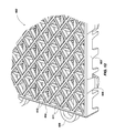
- FIG. 13 illustrates a rear view of the post structure configuration of the exemplary modular floor tile of FIG. 10 ;
- FIG. 14 illustrates a detailed rear view of the post structure configuration of the exemplary modular floor tile of FIG. 10 ;
- FIG. 15-A illustrates a side view of the exemplary modular floor tile of FIG. 10 ;
- FIG. 15-B illustrates a detailed side view of the exemplary modular floor tile of FIG. 10 ;
- FIG. 16 illustrates a detailed side view of the exemplary modular floor tile of FIG. 10 showing the deflection positions of the primary post structures and the downward displacement of the secondary post structures to engage or contact the floor.
- the present invention describes a method and system for controlling the deflection of a modular tile.
- FIGS. 1-3 illustrate a modular tile 100 configured to be interconnected into a tile array 105 to form a floor covering over a floor surface 101 , such as a tennis court, basketball court or any other suitable floor surface.
- the modular tiles 100 of the present invention are configured to provide enhanced “give” or, rather, means for absorbing impacts to facilitate improved safety for the various sporting activities typically conducted on the tile array 105 .
- the tiles 100 of the present invention can provide bounce or spring to those playing on the tile array 105 similar to wood flooring.
- Such tiles 100 can be formed from any suitable synthetic type material, such as a polymeric material, and formed using conventional molding techniques, such as injection molding, as well known by one of ordinary skill in the art.
- the modular tile 100 can include a top surface 110 with an opposite bottom side 112 or under-side.
- the top surface 110 can be smooth, perforated, grid-like, bumped or any other suitable surface desired for a synthetic tile floor covering.
- the bottom side 112 may also comprise a smooth, perforated, grid-like, bumped, or other suitable surface configuration.
- the top surface 110 can include a periphery with a square or rectangular shape, defining a front side 114 , a rear side 116 , a first side 118 and a second side 120 .
- Other suitable peripheral shapes for the tiles can also be employed, such as triangular, hexagonal, etc.
- Each of the front side, rear side, first side and second side can include side walls 122 with one or more coupling portions 124 integrated therewith.
- two adjacent sides such as the first side 118 and the front side 114 , can include one or more male coupling portions 126 while the opposite two sides, namely the second side 120 and the rear side 116 can include one or more female coupling portions 128 .
- the male and female coupling portions 126 and 128 of one tile can be configured to complimentarily mate with respective female and male coupling portions of other adjacently positioned tiles.
- the tiles 100 can be modularly interconnected, via the male and female coupling portions 126 and 128 , into columns and rows to form the tile array 105 for positioning over the floor surface 101 .
- the bottom side 112 of the tile 100 includes a support grid configured to support the top surface 110 of the tile 100 .
- the support grid can include multiple post structures 130 extending downward a length so as to suspend the side walls 122 of the tile 100 .
- the post structures 130 can include an upper portion 132 and one or more end portions 134 .
- the upper portion 132 can extend downward from the bottom side 112 of the tile 100 and the end portions can extend downward from the upper portion 132 .
- each post structure 130 can include two end portions 134 extending from the upper portion 132 .
- Each end portion 134 can include a radial surface end 136 , of which the radial surface end 136 can be configured to be positioned against and directly contact the floor surface 101 .
- the end portions 134 can be sized and configured to be flexible and resilient as well as durable.
- the end portions 134 of the post structures 130 are configured to absorb impacts applied at the top surface of the modular tile 100 .
- the radial surface end 136 of the end portions below the load L induces such end portions 134 to displace against the floor surface 101 and be forced in a lateral direction 148 to a lateral deflected position.
- the direction by which the end portions 134 slide and deflect can be dependent upon the placement and direction of the load L with respect to the radial surface end 136 of the end portions 134 .
- the end portions 134 can resiliently move back to their original position.
- the end portions 134 provide an upward spring force F due to the resilient characteristic of the end portions 134 .
- the end portions 134 facilitate impact absorbency or “give” in the tile to provide a greater degree of safety for those on the tiles 100 as well as provide additional spring in the tiles 100 .
- the end portions 134 in this embodiment, can resiliently deflect while the upper portion 132 of the post structures 130 can be configured to have a substantially maintained position.
- the upper portion 132 of each of the post structures 130 provides the necessary support for the tiles 100 while the end portions 134 provide the impact absorbency component for the tiles 100 .
- the end portions 134 of the post structures 130 can be modified in size and configuration according to the amount of controlled deflection or impact absorbency desired for an intended use or activity for playing on the tiles 100 .
- the type of synthetic material employed for the tiles 100 can also be a factor for the size and configuration of the post structures 130 to provide the amount of deflection or impact absorbency desired in the tiles 100 .
- each post structure 130 can include a circular periphery 142 .
- the upper portion can have a cylindrical shape or conical shape.
- each post structure 130 can include two end portions 132 , spaced apart, with opposing outer circular peripheries 144 .
- the end portions 134 for one post structure 130 can be oriented to allow the end portions 134 to controllably deflect in a first bi-lateral direction 150 and the end portions 134 for an adjacent post structure 130 can be oriented to allow the end portions 134 to controllably deflect laterally in a second bi-lateral direction 152 .
- the first bi-lateral direction 150 can be transverse to the second bi-lateral direction 152 .
- the orientation of the end portions 134 in the post structure array 135 can be a checkered orientation configuration.
- Other orientation configurations can also be implemented, such as staggered orientation configurations, row orientation configurations, column orientation configurations, etc.
- a column orientation configuration can include the orientation of the end portions 134 being similarly oriented within one column with the first bilateral direction 150 and an adjacent column can include orientations of the end portions 134 with the second bilinear direction 152 .
- orientation configurations can be implemented in the post structures to control the directional deflection or movement of the end portions 134 and, further, control the impact absorbency of the tiles 100 .
- the upper portion 232 of the post structures 230 can include a square periphery 242 .
- the two end portions 234 for one post structure 230 , can be elongated at least partially along a width 238 of the post structure 230 , spaced apart, and oriented substantially parallel to each other.
- the elongated structure of the end portions 234 can facilitate resilient deflection of the end portions 234 with controlled bi-lateral movement, as in the embodiment previously set forth.
- the orientation configuration of the respective end portions 234 in the post structure array 235 can be in a checkered orientation configuration, or any other suitable orientation configuration as set forth in the previous embodiment.
- FIGS. 6 and 7 illustrate another embodiment of the support grid of the modular tile 300 including the post structure array 335 .
- the post structures 330 can include a single end portion 334 configured to extend downward from the upper portion 332 of the post structure 330 .
- the end portion 334 can include a radial surface end 336 to facilitate resilient deflection in a lateral direction dependent upon the position of the load L applied at the top surface 310 .
- the end portions 334 can be an elongated projection extending downward from the upper portion 332 of the post structure 330 . Further, the end portions 334 can resiliently deflect in any suitable lateral direction 350 with respect to a longitudinal axis 352 of the post structure 330 .
- FIG. 8 illustrates another embodiment of the post structure array 435 at the bottom side 412 of the tile 400 .
- the post structures 430 can include an end portion 434 with a cross-sectional area similar to the upper portion 432 of the post structures 430 .
- the cross-section of each of the post structures 430 can be sized and configured such that the end portions 434 can provide the impact absorbency intended by being resiliently deflectable while also providing sufficient support at the upper portion 432 of the post structures 430 .
- the end portions 434 can include the radial surface end 436 to readily facilitate lateral sliding against the floor surface 101 upon a load L being applied to the top surface 410 of the tile 100 .
- the post structures 430 can be sized and configured so that the end portions 434 can resiliently deflect in any suitable lateral direction 450 with respect to a longitudinal axis 452 of the post structure 430 , as in the previous embodiment.
- the post structures 430 can be sized and configured to be elongated along their width to control the direction of lateral movement by which the end portions 434 can bend, similar to that described and depicted with respect to FIG. 5 .
- FIG. 9 illustrates another embodiment of the tile 500 with the post structure array 535 .
- the post structures 530 in this embodiment can taper downward to an end portion 534 , wherein the end portion 534 can include a radial surface end 536 .
- the end portion 534 of each of the post structures 530 can be resiliently deflectable upon a load L being applied to the top surface 510 of the tiles 500 , similar to the previous embodiments.
- the post structures 530 in this embodiment can be conical, pyramidal, or any other suitable tapering post structure, such as an elongated width structure to facilitate directional control in the deflection of the end portions 534 .
- the end portions 534 can resiliently bend in any suitable lateral direction 550 with respect to a longitudinal axis 552 of the post structure 530 .
- the direction by which the end portions resiliently deflect can be substantially controlled to bend with bi-lateral movement.
- the post structures of the present invention can include various configurations that can deflect under various ranges of loads and impacts.
- the configuration of the post structures can be formed with deflection control to deflect at particular load ranges by, for example, manipulating the radius of curvature of the end portions, sizing the cross-sectional area of the end portions and/or sizing the upper portions of the post structures to withstand over-deflection, manipulating the orientation configuration of the post structures to control the direction of deflection of the post structures, etc.
- the radius of curvature in the end portions' radial surface end can be smaller in the embodiment depicted in FIG. 9 compared to the radius of curvature in the end portions depicted in FIG.
- the end portions depicted in FIG. 8 may require a larger load or impact to effect deflection of the end portions than that required in the end portions depicted in FIG. 9 .
- Such various configurations of the post structures can be determined by one of ordinary skill in the art to facilitate the controlled deflection desired for a given type of activity predicted to be played on the array of tiles.
- FIGS. 10-16 illustrate various features of a modular tile configuration according to another exemplary embodiment of the present invention.
- the modular tile illustrated in FIGS. 10-16 is similar to the exemplary modular tiles discussed above and shown in the drawings. However, this particular modular tile embodies an alternative controlled deflection concept.
- FIG. 10 illustrated is a perspective view of an exemplary modular tile 600 having a bi-level or multi-level surface structure.
- other single level surface tile configurations may also be used with the controlled deflection concept discussed herein, thus the illustration of a bi-level surface is not meant to be limiting in any way.
- the controlled deflection concept discussed herein with reference to FIGS. 10-16 may be incorporated into any single surface tile configuration, such as those discussed above in reference to FIGS. 1-9 .
- the modular tile 600 is configured to be interconnected with a plurality of other tiles to form a tile array, such as the one described above, for the purpose of forming a floor covering over a floor surface, similar to those identified above.
- the modular tile 600 shown in FIG. 10 is configured to provide enhanced “give” or, rather, means for absorbing impacts to facilitate improved safety for the various sporting activities typically conducted on the tile array.
- the modular tile 600 of the present invention can provide bounce or spring to those playing on the tile array in a similar manner as wood flooring and the like.
- the modular tile 600 is also configured to perform other functions that will be addressed below or that will be obvious to those skilled in the art.
- the modular tile 600 may be formed from any suitable synthetic type of material, such as a polymeric material, and may be formed using conventional molding techniques, such as injection molding, and others that are commonly known.
- the modular tile 600 includes a surface configuration.
- the tile 600 can include a surface 610 with an opposite bottom side or under-side and sidewalls defining a periphery.
- the top surface 610 can be smooth, perforated, grid-like, bumped or any other suitable surface desired for a synthetic tile floor covering.
- the bottom side may also be smooth, perforated, grid-like, bumped or any other suitable surface.
- the surface 610 of the modular tile 600 comprises a bi-level surface, or a plurality of surfaces.
- An upper surface 611 is defined by a diamond-shaped grid-like pattern.
- a lower surface 613 is defined by a square-shaped grid-like pattern formed and operable with the upper surface 611 .
- the modular tile 600 can include a periphery with a square or rectangular shape, defining a front side 614 , a rear side 616 , a first side 618 and a second side 620 .
- Other suitable peripheral shapes for the modular tile 600 can also be employed, such as triangular, hexagonal, etc.
- Each of the front side 614 , rear side 616 , first side 618 and second side 620 can include side walls 622 with one or more coupling portions 624 integrated therewith.
- two adjacent sides such as the first side 618 and the front side 614 , can include one or more male coupling portions 626 while the opposite two sides, namely the second side 620 and the rear side 616 can include one or more female coupling portions 628 .
- the male and female coupling portions 626 and 628 of one tile can be configured to complimentarily mate with respective female and male coupling portions of other adjacently positioned tiles.
- the several tiles can be modularly interconnected, via the male and female coupling portions 626 and 628 , into columns and rows to form a tile array for positioning over the surface of a floor.
- FIGS. 13 and 14 illustrated are respective rear views of the modular tile 600 shown in FIGS. 10-12 , and described above, with FIG. 14 illustrating a detailed rear view of a portion of the modular tile 600 .
- the bottom side of the tile 600 includes a support grid configured to support the top surface 610 of the tile 600 .
- the support grid can include multiple post structures in the form of primary and secondary post structures 630 and 660 , each extending downward a length from the bottom side.
- the primary post structures 630 include an upper portion 632 and one or more end portions 634 .
- the upper portion 632 can extend downward from the bottom side of the tile 600 and the end portions 634 can extend downward from the upper portion 632 .
- the primary post structure 630 may comprise any shape, size, and configuration, such as those discussed above in relation to FIGS. 1-9 .
- the secondary post structures 660 include an upper portion 662 and one or more end portions 664 .
- the upper portion 662 can extend downward from the bottom side of the tile 600 and the end portions 664 can extend downward from the upper portion 662 .
- These also can be any shape, size, and configuration.
- the primary and secondary post structures 630 and 660 are arranged about the bottom side of the tile according to any conceivable arrangement, which may include a patterned arrangement, a random arrangement, and a layered arrangement.
- the modular tile 600 comprises a plurality of primary post structures 630 interspaced with a plurality of secondary post structures 660 to comprise the support for the modular tile 600 , and particularly the surface 610 of the modular tile 600 .
- each secondary post structure 660 is positioned to be immediately adjacent or surrounded by four primary post structures 630 located at quadrant positions.
- each primary post structure 630 is immediately adjacent or surrounded by at least four secondary post structures 660 .
- This alternating pattern of primary and secondary post structures is repeated several times to comprise the support structure of the modular tile 600 .
- the particular post structure pattern, as well as the spacing between the various primary and secondary posts, as shown in FIGS. 13 and 14 is not meant to be limiting in any way, but instead comprises merely one exemplary arrangement.
- the primary post structures 630 are formed from or are extensions of or are coupled to the underside of the lower surface 613 .
- the primary post structures 630 are intended to contact the floor or ground at all times, and are considered the primary support structures for the modular tile 600 .
- the primary post structures 630 are configured to deflect laterally instead of to deform (e.g., mashing).
- the secondary post structures are formed from or are extensions of or are coupled to the underside of the upper surface 611 .
- the secondary post structures 660 are designed to terminate a pre-determined distance so that their ends are not in contact with the floor when the modular tile 600 is subject to non-deflecting loads (loads below the primary load threshold described below) or no load at all.
- the secondary post structures 660 are configured to contact the floor or ground only in the event all or a portion of the upper surface 610 of the tile is subject to an applied load capable of deflecting the primary post structures 630 a sufficient distance to cause the secondary post structures 660 to displace toward and contact the floor or ground.
- Some of the purposes or functions of the secondary post structures 660 are to control the deflection of the primary post structures 630 , or rather to limit the degree of deflection of the primary post structures 630 ; to improve the durability of the modular tile 600 in response to applied loads; to increase the load bearing capabilities of the modular tile 600 , to help prevent premature or inadvertent damage to the modular tile 600 under applied loads; and to preserve and improve the integrity, functionality, and operability of the modular tile 600 .
- the secondary post structures of the modular tile 600 described herein may also be incorporated into any of the modular tile configurations described above and shown in FIGS. 1-9 .
- the post structures 130 identified above and illustrated in FIG. 3 may be termed as primary post structures, with the modular tile 100 comprising a plurality of secondary post structures positioned between or arranged about the primary post structures according to a pre-determined post structure pattern or arrangement, as taught herein.
- the concept of primary and secondary post structures as disclosed herein may also be incorporated into other floor tile designs not specifically described and shown herein, as will be appreciated and apparent to those skilled in the art.
- FIGS. 15-A and 15 -B illustrated are respective side views of the modular tile 600 shown in FIGS. 10-14 and described above, with FIG. 15-B illustrating a detailed side view of a portion of the modular tile 600 .
- the primary post structures 630 extend downward from the underside of the lower surface (not shown, but see surface 613 in FIG. 12 ) and comprise end portions 634 that are configured to be in contact with the floor or ground 601 at all times.
- the secondary post structures 660 extend downward from the underside of the upper surface (not shown, but see upper surface 611 in FIG. 12 ) and comprise end portions 664 configured to terminate at a position above the floor 601 a distance x. This distance x may vary as desired.
- the secondary post structures 660 may comprise the same or a different length than the primary post structures 630 , depending upon the surface configuration of the modular tile 600 .
- the secondary post structures 660 may comprise a different length than the primary post structures both are extending from a single surface configuration; and they may comprise the same or a different length if each is extending from different surfaces of a bi-level surface configuration.
- the size of the primary and secondary post structures 630 and 660 may be the same or different. In essence, the size, shape, configuration, pattern, location, and number of primary and secondary post structures, and may vary depending upon the functional performance desired to be achieved by a particular modular tile.
- the secondary post structures 660 are configured to activate and contact the floor 601 only upon sufficient deflection of the primary post structures 630 adjacent the secondary post structures 660 in response to a load or impact L. Depending upon the distribution area of the applied load to the surface 610 of the modular tile 600 , one or more primary post structures 630 may deflect a sufficient distance to cause one or more secondary post structures 660 to contact the floor 601 .
- the end portions 634 of the primary post structures 630 are configured to absorb impacts applied at the surface 610 of the modular tile 600 .
- the end portions 634 of the primary post structures 630 within the distribution area of the load L are caused to displace against the floor surface 601 and be forced in a lateral direction 648 to a lateral deflected position.
- FIG. 16 illustrates several primary post structures 630 deflecting in one direction in response to the load L, as well as the deflection of primary post structure 630 - b in another opposite direction.
- the magnitude of the load L will determine the magnitude of deflection of the primary post structures 630 .
- Some loads may cause nominal or marginal deflection of the primary post structures 630 such that the secondary post structures 660 are not caused to contact the floor 601 .
- the primary post structures 630 are caused to laterally deflect, which results in the displacement of the surface 610 of the modular tile 600 toward the floor 601 as a result of the shortening effect on the primary post structures 630 caused by their deflection.
- the secondary post structures 660 are caused to also displace in a downward direction towards the floor 601 .
- the end portions 664 of the secondary post structures 660 are caused to engage or come in contact with the floor 601 , thus activating the secondary post structures 660 as support members for the modular tile 600 .
- the secondary post structures 660 function as additional supports for the modular tile 601 in response to the load L.
- the secondary post structures 660 are also designed to support the primary post structures 630 , up to a pre-determined threshold. Of particular note is the ability of the secondary post structures 660 to control or limit the deflection of the primary post structures 630 and support the modular tile 600 and primary post structures 630 under a sufficient given load L by contacting the floor 601 .
- the secondary post structures 660 function as additional support members of the modular tile 600 under loads large enough to deflect the primary post structures 630 and cause the secondary post structures 660 to come in contact with the floor 601 .
- the breach of a primary load threshold at and above 160 psi will cause the primary post structures 630 to deflect enough to enable the secondary post structures 660 to displace and contact the floor.
- the primary load threshold for causing the primary post structures to deflect enough to cause the secondary post structures to activate and displace to contact the floor may be pre-determined and may be set at any desirable limit, depending upon, among other things, the construction, configuration, post structure pattern, and/or material make-up of the modular tile.
- this primary load threshold will range between 100 and 300 psi, as this is a reasonable range corresponding to the weight range of different individuals that might be using the tiles, and the forces that may be induced upon the tiles by them.
- the modular tile also has a secondary load threshold. Loads below this secondary load threshold and in excess of the primary load threshold define acceptable operating conditions that allow the modular tile to remain functional without deflection or deformation of the secondary post structure.
- This secondary load threshold is also pre-determined and may be set at any desirable limit.
- the secondary load threshold defines the load that the secondary post structures, along with the deflected post structures, may bear without deflecting or deforming (e.g., being mashed), thus possibly damaging the modular tile. Loads in excess of this secondary load threshold will cause a degree of deflection and/or deformation of the secondary post structures, some of which may be acceptable, and which may result without damage to the modular tile.
- the primary and secondary posts are elastically deformable up to a pre-determined load.
- the modular tile is also designed with a maximum load threshold.
- the maximum load threshold describes or defines the load that modular tile is able to bear without being damaged. Again, this maximum load threshold is pre-determined and may be set at any desirable limit. Loads in excess of this maximum load threshold will cause irreversible damage to the modular tile and cause the primary and secondary posts, the surface, and/or other vital components of the modular tile to inelastically deform.
- the end portions 634 of the primary post structures 630 resiliently move back to their original position, thus also causing the end portions 664 of the secondary post structures 660 to disengage the floor 601 and return to their normal, inactive position. Furthermore, in the event the end portions 634 are in a load bearing deflected position, they are capable of providing an upward spring force F, due to the resilient characteristics of the end portions 634 . With this arrangement, the end portions 634 facilitate impact absorbency or “give” in the tile to provide a greater degree of safety for those using the modular tiles 600 . They also provide additional spring in the tiles 600 .
- the end portions 634 in this embodiment, can resiliently deflect while the upper portion 632 of the post structures 630 can be configured to have a substantially maintained or stationary position.
- the upper portion 632 of each of the post structures 630 provides the necessary support for the tiles 600 while the end portions 634 provide the impact absorbency component for the modular tiles 600 .
- the end portions 634 of the primary post structures 630 can be modified in size and configuration according to the amount of controlled deflection or impact absorbency desired for an intended use or activity for playing on the modular tiles 600 .
- end portions 634 may further comprise radial end surfaces designed to facilitate the sliding and lateral deflection of the end portions 634 , which radial end surfaces are described above in relation to FIGS. 1-9 .
- the type of synthetic material employed for the modular tiles 600 can also be a factor for the size and configuration of the primary post structures 630 to provide the amount of deflection or impact absorbency desired in the modular tiles 600 .
- the secondary post structures and their ability to control the deflection of the primary post structures also functions to provide the modular tile with controlled shock absorption, meaning that the modular tile comprises an increased elastic capacity to “give” when subject to an applied load.
- Another advantage is to provide the modular tile with an increase in bounce or spring as compared to prior related modular tiles.
- the primary post structures are able to essentially spring back into their initial position once the load is removed. This also functions to provide greater ball rebound, as well as to assist, to a limited degree, jumping by an individual.
- Still another advantage to providing a modular tile with deflecting primary post structures and controlling or limiting their deflection with secondary post structures is that the modular tile comprises an improved surface feel. Due to the controlled deflection, the tile is and feels less rigid. Unlike prior related modular tiles existing in the art, the “give” in the tile results in lower and/or absorbed impact forces, thus reducing injury to individuals using the array of modular tiles.
- the term “preferably” is non-exclusive where it is intended to mean “preferably, but not limited to.” Any steps recited in any method or process claims may be executed in any order and are not limited to the order presented in the claims. Means-plus-function or step-plus-function limitations will only be employed where for a specific claim limitation all of the following conditions are present in that limitation: a) “means for” or “step for” is expressly recited; b) a corresponding function is expressly recited; and c) structure, material or acts that support that structure are expressly recited. Accordingly, the scope of the invention should be determined solely by the appended claims and their legal equivalents, rather than by the descriptions and examples given above.
Abstract
Description
Claims (20)
Priority Applications (1)
| Application Number | Priority Date | Filing Date | Title |
|---|---|---|---|
| US14/090,845 US8955268B2 (en) | 2004-02-25 | 2013-11-26 | Modular tile with controlled deflection |
Applications Claiming Priority (4)
| Application Number | Priority Date | Filing Date | Title |
|---|---|---|---|
| US54748904P | 2004-02-25 | 2004-02-25 | |
| US11/065,192 US7748177B2 (en) | 2004-02-25 | 2005-02-24 | Modular tile with controlled deflection |
| US12/789,161 US8596023B2 (en) | 2004-02-25 | 2010-05-27 | Modular tile with controlled deflection |
| US14/090,845 US8955268B2 (en) | 2004-02-25 | 2013-11-26 | Modular tile with controlled deflection |
Related Parent Applications (1)
| Application Number | Title | Priority Date | Filing Date |
|---|---|---|---|
| US12/789,161 Continuation US8596023B2 (en) | 2004-02-25 | 2010-05-27 | Modular tile with controlled deflection |
Publications (2)
| Publication Number | Publication Date |
|---|---|
| US20140215950A1 US20140215950A1 (en) | 2014-08-07 |
| US8955268B2 true US8955268B2 (en) | 2015-02-17 |
Family
ID=34914952
Family Applications (4)
| Application Number | Title | Priority Date | Filing Date |
|---|---|---|---|
| US11/065,192 Expired - Fee Related US7748177B2 (en) | 2004-02-25 | 2005-02-24 | Modular tile with controlled deflection |
| US12/789,161 Active US8596023B2 (en) | 2004-02-25 | 2010-05-27 | Modular tile with controlled deflection |
| US13/079,572 Active US8424257B2 (en) | 2004-02-25 | 2011-04-04 | Modular tile with controlled deflection |
| US14/090,845 Active US8955268B2 (en) | 2004-02-25 | 2013-11-26 | Modular tile with controlled deflection |
Family Applications Before (3)
| Application Number | Title | Priority Date | Filing Date |
|---|---|---|---|
| US11/065,192 Expired - Fee Related US7748177B2 (en) | 2004-02-25 | 2005-02-24 | Modular tile with controlled deflection |
| US12/789,161 Active US8596023B2 (en) | 2004-02-25 | 2010-05-27 | Modular tile with controlled deflection |
| US13/079,572 Active US8424257B2 (en) | 2004-02-25 | 2011-04-04 | Modular tile with controlled deflection |
Country Status (3)
| Country | Link |
|---|---|
| US (4) | US7748177B2 (en) |
| EP (1) | EP1727950B1 (en) |
| WO (1) | WO2005082081A2 (en) |
Families Citing this family (95)
| Publication number | Priority date | Publication date | Assignee | Title |
|---|---|---|---|---|
| US7748177B2 (en) * | 2004-02-25 | 2010-07-06 | Connor Sport Court International, Inc. | Modular tile with controlled deflection |
| US7690160B2 (en) | 2004-07-23 | 2010-04-06 | Moller Jr Jorgen J | Modular floor tile system with transition edge |
| US8407951B2 (en) | 2004-10-06 | 2013-04-02 | Connor Sport Court International, Llc | Modular synthetic floor tile configured for enhanced performance |
| US8397466B2 (en) | 2004-10-06 | 2013-03-19 | Connor Sport Court International, Llc | Tile with multiple-level surface |
| US20090235605A1 (en) * | 2004-10-06 | 2009-09-24 | Thayne Haney | Method of Making A Modular Synthetic Floor Tile Configured For Enhanced Performance |
| AT501449B1 (en) * | 2004-12-21 | 2011-02-15 | Hrovath Josef Dipl Ing | CONNECTING DEVICE FOR CONNECTING COMPONENTS |
| USD656250S1 (en) | 2005-03-11 | 2012-03-20 | Connor Sport Court International, Llc | Tile with wide mouth coupling |
| US20060265975A1 (en) * | 2005-05-04 | 2006-11-30 | Kurt Geffe | Floor tile |
| US7587865B2 (en) * | 2005-06-02 | 2009-09-15 | Moller Jr Jorgen J | Modular floor tile with multi level support system |
| US7571572B2 (en) * | 2005-06-02 | 2009-08-11 | Moller Jr Jorgen J | Modular floor tile system with sliding lock |
| US7958681B2 (en) * | 2005-06-02 | 2011-06-14 | Moller Jr Jorgen J | Modular floor tile with nonslip insert system |
| US8099915B2 (en) * | 2005-06-02 | 2012-01-24 | Snapsports Company | Modular floor tile with resilient support members |
| WO2007092958A2 (en) * | 2006-02-09 | 2007-08-16 | University Of Notre Dame Du Lac | Flooring apparatus for reducing impact energy during a fall |
| US8919066B2 (en) | 2006-02-09 | 2014-12-30 | University Of Notre Dame Du Lac | Flooring apparatus for reducing impact energy during a fall |
| US7900416B1 (en) | 2006-03-30 | 2011-03-08 | Connor Sport Court International, Inc. | Floor tile with load bearing lattice |
| US7571573B2 (en) * | 2006-04-11 | 2009-08-11 | Moller Jr Jorgen J | Modular floor tile with lower cross rib |
| US8020783B2 (en) * | 2006-07-19 | 2011-09-20 | Backman Jr James Joseph | Radiant mat grid |
| WO2008045447A2 (en) * | 2006-10-09 | 2008-04-17 | Fieldturf Tarkett Inc. | Tile for a synthetic grass system |
| US7634876B2 (en) * | 2006-12-08 | 2009-12-22 | Moller Jr Jorgen J | Modular floor locator apparatus |
| JP4570675B2 (en) * | 2008-09-04 | 2010-10-27 | 株式会社ファルテック | floor mat |
| US7827742B2 (en) * | 2009-01-08 | 2010-11-09 | Vicente Francisco Sansano Marti | Removable covering for surfaces |
| US8646242B2 (en) * | 2009-09-18 | 2014-02-11 | Snap Lock Industries, Inc. | Modular floor tile with connector system |
| US9339981B2 (en) | 2009-10-30 | 2016-05-17 | Macneil Ip Llc | Method of making a floor tile with elastomer jacketed support members |
| US20130095295A1 (en) * | 2009-10-30 | 2013-04-18 | Macneil Ip Llc | Floor tile with overmold crush pads |
| US8640403B2 (en) * | 2009-10-30 | 2014-02-04 | Macneil Ip Llc | Floor tile with elastomer jacketed bottom support members |
| US8535785B2 (en) * | 2009-10-30 | 2013-09-17 | Macneil Ip Llc | Floor tile |
| US9180640B2 (en) | 2009-10-30 | 2015-11-10 | Macneil Ip Llc | Method of making a floor tile with overmolded pads |
| US8993098B2 (en) | 2011-08-25 | 2015-03-31 | Macneil Ip Llc | Two-shot injection molded floor tile with vent hole |
| US9181697B2 (en) | 2009-10-30 | 2015-11-10 | Macneil Ip Llc | Floor tile having a latch and loop structure |
| GB2475914B (en) * | 2009-12-07 | 2014-03-26 | Kee Safety Ltd | Tread module for a walkway or stairway with severable sub-module portions |
| US8881482B2 (en) | 2010-01-22 | 2014-11-11 | Connor Sport Court International, Llc | Modular flooring system |
| US8683769B2 (en) | 2010-01-22 | 2014-04-01 | Connor Sport Court International, Llc | Modular sub-flooring system |
| US8505256B2 (en) | 2010-01-29 | 2013-08-13 | Connor Sport Court International, Llc | Synthetic floor tile having partially-compliant support structure |
| EP3153626A1 (en) * | 2010-02-11 | 2017-04-12 | Brock International | Load supporting panel having impact absorbing structure |
| WO2012017098A1 (en) * | 2010-08-05 | 2012-02-09 | Butech Building Technology, S.A. | Process for producing pieces of removable floor covering and removable floor covering |
| US20120094057A1 (en) * | 2010-10-14 | 2012-04-19 | Joel Patrick Bartlett | Porous anti-slip floor covering |
| IT1403088B1 (en) * | 2010-11-10 | 2013-10-04 | Tenax Spa | ELEMENT FOR FLOORING IN PLASTIC MATERIAL WITH RETICULAR STRUCTURE, PROCEDURE FOR THE PRODUCTION OF THE SAME AND USE OF THE FLOORING ELEMENT |
| CN103370485B (en) * | 2011-11-11 | 2017-02-22 | 胡钢 | Building-block floor tiles |
| EP2828447A4 (en) * | 2012-01-03 | 2016-07-13 | Univ Notre Dame Du Lac | Flooring apparatus for reducing impact energy during a fall |
| GB2495790B (en) * | 2012-02-07 | 2014-07-16 | Ryan Patrick Hurson | A floor tile |
| DE102013100051B4 (en) * | 2012-02-16 | 2018-02-08 | Hamberger Industriewerke Gmbh | Removable outdoor flooring |
| US9187910B2 (en) * | 2012-10-17 | 2015-11-17 | Frank Tortorella | Carpet tiling system and method of installation |
| AU2014253669B2 (en) * | 2013-04-14 | 2018-05-17 | Combitile Pty Ltd | Interlocking and shock attenuating tiling systems |
| US8919069B2 (en) * | 2013-04-24 | 2014-12-30 | Sof'solutions, Inc. | Systems and methods for selectively releasable modular tile |
| US9273471B2 (en) | 2013-06-14 | 2016-03-01 | George L. Fischer | Non-slip surfaces and methods for creating same |
| USD704961S1 (en) * | 2013-07-03 | 2014-05-20 | Wearwell | Studded molded mat |
| US8973328B2 (en) | 2013-07-12 | 2015-03-10 | Macneil Ip Llc | Floor tile expansion joint |
| US9121182B2 (en) | 2013-09-25 | 2015-09-01 | George Atkinson | Weight room flooring system |
| US9038341B2 (en) * | 2013-10-07 | 2015-05-26 | Newtechwood, Ltd. | Modular flooring system |
| US8756882B1 (en) | 2013-10-31 | 2014-06-24 | Le Groupe Dsd Inc. | Tile for use in a modular flooring system |
| US9416540B2 (en) * | 2013-11-27 | 2016-08-16 | Tapco International Corporation | Dual-arch roof tile |
| US9765531B2 (en) | 2014-01-08 | 2017-09-19 | George Atkinson | Weight room floor covering |
| US9863155B2 (en) * | 2014-03-04 | 2018-01-09 | Connor Sport Court International, Llc | Synthetic flooring apparatus |
| US20150252563A1 (en) * | 2014-03-04 | 2015-09-10 | Conner Sport Court International, LLC | Synthetic flooring apparatus |
| JP6161648B2 (en) * | 2014-05-26 | 2017-07-12 | 豊田鉄工株式会社 | Stacked composite interior parts |
| CN104088440A (en) * | 2014-07-23 | 2014-10-08 | 四川中塑高分子材料有限公司 | Exercise floor with damping device enabling people to be in contact with ground more stably |
| WO2016112402A2 (en) * | 2015-01-09 | 2016-07-14 | Malmquist M Casey | Pick mat locking system |
| US9609971B2 (en) | 2015-01-26 | 2017-04-04 | Mmi Andersen Company Llc | Movement-resistant floor mat |
| WO2016144318A1 (en) * | 2015-03-09 | 2016-09-15 | Connor Sport Court International, Llc | Synthetic flooring apparatus |
| FR3036718B1 (en) * | 2015-05-28 | 2018-08-31 | Tarkett Gdl S.A. | NON-SLIP FLOOR COATING SLAB |
| USD839634S1 (en) * | 2015-06-15 | 2019-02-05 | Superior Manufacturing Group Europe Bv | Doormat |
| USD768315S1 (en) * | 2015-06-25 | 2016-10-04 | Mpi S.R.L. | Floor panel |
| US9328520B1 (en) * | 2015-07-17 | 2016-05-03 | Matthew Kriser | High strength in-floor decoupling membrane |
| US10072383B1 (en) * | 2015-12-29 | 2018-09-11 | Stiles Manufacturing, LLC | Interlocking traffic tile for one piece water permeable paver |
| US9617698B1 (en) * | 2015-12-29 | 2017-04-11 | Stiles Manufacturing, LLC | Permeable paver and modular light system |
| USD972175S1 (en) | 2015-12-29 | 2022-12-06 | Airlite Plastics Co. | Permeable paver |
| US10563361B2 (en) | 2016-01-12 | 2020-02-18 | Ch3 Solutions, Llc | System and method for customizing a playing field |
| US10060083B2 (en) * | 2016-01-12 | 2018-08-28 | Versacourt, Llc | Spring tension system for tile |
| EP3199721A1 (en) | 2016-02-01 | 2017-08-02 | Connor Sport Court International, LLC | Modular floor tile and method of connecting adjacent flooring components |
| CA3022867C (en) * | 2016-05-02 | 2019-04-23 | Easybuild Bvba | Modular presentation system for the display and support of goods and build-up method therefor |
| US10137639B2 (en) * | 2016-05-12 | 2018-11-27 | R&L Marketing & Sales, Inc. | Method of fabricating an ultrasonically welded mat unit |
| US10907930B2 (en) * | 2016-07-08 | 2021-02-02 | Bryce L. Betteridge | Impact absorbing padding system with elastomeric sub-surface structure |
| US10738484B2 (en) | 2016-07-11 | 2020-08-11 | 308, Llc | Shock absorbing interlocking floor system |
| USD866006S1 (en) * | 2016-10-03 | 2019-11-05 | One Mission, LLC | Modular flooring tile |
| KR101769737B1 (en) * | 2017-04-20 | 2017-08-18 | 박서영 | Integrated assembly type grass protection mat and method for constituting grass protection mat |
| DE102017004000A1 (en) * | 2017-04-26 | 2018-10-31 | Ewald Dörken Ag | decoupling membrane |
| USD880011S1 (en) * | 2017-12-04 | 2020-03-31 | Signature Systems Group Llc | Modular flooring tile |
| USD934452S1 (en) | 2017-12-04 | 2021-10-26 | Signature Systems Group Llc | Modular flooring tile with cable channels |
| USD880012S1 (en) * | 2017-12-04 | 2020-03-31 | Signature Systems Group Llc | Modular flooring tile with cable channels |
| US10914081B2 (en) * | 2017-12-15 | 2021-02-09 | Wearwell, Llc | Interlocking modular mat with sponge insert |
| TWM579195U (en) * | 2019-02-22 | 2019-06-11 | 鴻耀新技股份有限公司 | Assembled type plastic floor |
| CN110199932B (en) * | 2019-05-09 | 2024-01-26 | 桂林理工大学 | Aquatic plant planting plate for aquarium |
| US10912443B1 (en) * | 2019-07-31 | 2021-02-09 | R&L Marketing & Sales, Inc. | Modular mat system |
| US11596253B2 (en) | 2019-07-31 | 2023-03-07 | R&L Marketing & Sales, Inc. | Modular mat system |
| US11060301B2 (en) | 2019-07-31 | 2021-07-13 | R&L Marketing & Sales, Inc. | Modular mat system |
| USD924444S1 (en) | 2019-11-26 | 2021-07-06 | Soccer Park, LLC | Floor tile |
| BR112022010155A2 (en) * | 2019-11-29 | 2022-08-09 | Magic Shields Inc | FLOOR MATERIAL SYSTEM |
| US20210210060A1 (en) * | 2020-01-06 | 2021-07-08 | Carey Widder | Acoustic attenuation mat |
| US11274454B2 (en) * | 2020-01-29 | 2022-03-15 | Snap Lock Industries, Inc. | Traction enhanced floor tile apparatus and system |
| SE2050195A1 (en) * | 2020-02-21 | 2021-08-22 | Cenesy Ab | Flooring system |
| TW202144657A (en) * | 2020-05-25 | 2021-12-01 | 佳瑤企業股份有限公司 | Floor mat with moisture-proof effect comprising a base and a mat body that are not easy to produce peculiar smell and breed bacteria |
| EP4158130A1 (en) * | 2020-05-31 | 2023-04-05 | Gordon Albin Osbak | Interlockable modular floor tile and method of assembling same |
| KR102317642B1 (en) * | 2020-12-22 | 2021-10-26 | 삼원액트 주식회사 | Unit bracket, bracket |
| NL2027779B1 (en) | 2021-03-19 | 2022-09-29 | Supersub Sportsystems B V | Temperature-controlled sports field |
| CN216822705U (en) * | 2022-03-01 | 2022-06-28 | 苏州恒瑞达家用地垫有限公司 | Hidden concatenation ground mat |
Citations (359)
| Publication number | Priority date | Publication date | Assignee | Title |
|---|---|---|---|---|
| US69297A (en) | 1867-09-24 | Improved pavement | ||
| US321403A (en) | 1885-06-30 | Pavement | ||
| US658868A (en) | 1899-02-06 | 1900-10-02 | Henry Rosenbaum | Wall, floor, or ceiling for buildings. |
| US1177231A (en) | 1915-07-19 | 1916-03-28 | Charles J Carter | Flooring. |
| US1195289A (en) | 1916-08-22 | Floob construction | ||
| US1425324A (en) | 1918-11-15 | 1922-08-08 | Hollar Company | Safe or vault wall |
| US1472956A (en) | 1923-11-06 | Building construction | ||
| US1824571A (en) | 1927-05-06 | 1931-09-22 | Henry F Richardson | Insert for underfloor wiring ducts or the like |
| US1896957A (en) | 1930-04-07 | 1933-02-07 | Hutcheson William James Fraser | Reenforcement connected with reenforced concrete buildings, slabs, playgrounds, and such like |
| US1971320A (en) | 1934-08-21 | Panel key construction | ||
| US2082563A (en) | 1935-05-21 | 1937-06-01 | Bauer William Stanley | Mat for the use of golfers |
| US2225828A (en) | 1940-05-03 | 1940-12-24 | Philco Corp | Nonskid tire track |
| US2653525A (en) | 1950-01-16 | 1953-09-29 | Mcguire John Sargeant | Landing mat |
| US2680698A (en) | 1949-12-03 | 1954-06-08 | Schnee Robert Francis | Plastic floor coverings |
| US2735166A (en) | 1956-02-21 | Hand hole forming method for cellular | ||
| US2810672A (en) | 1956-06-08 | 1957-10-22 | Don A Taylor | Floor mats for automobiles |
| US3015136A (en) | 1957-10-17 | 1962-01-02 | Pawling Rubber Corp | Resilient mat structure |
| US3122073A (en) | 1960-01-11 | 1964-02-25 | Robert E Masse | Insulated deck structure |
| US3222834A (en) | 1963-04-23 | 1965-12-14 | William G Taft | Carpet retaining means |
| US3251076A (en) | 1965-03-19 | 1966-05-17 | Daniel M Burke | Impact absorbing mat |
| US3310906A (en) | 1965-07-22 | 1967-03-28 | Fowler Knobbe & Gambrell | Toy construction blocks and assembly |
| US3318476A (en) | 1965-01-26 | 1967-05-09 | Jones & Laughlin Steel Corp | Junction unit for underfloor wire distribution system |
| US3332192A (en) | 1964-06-09 | 1967-07-25 | Kessler Gerald | Interlocking panel assembly |
| US3350013A (en) | 1965-11-22 | 1967-10-31 | Arthur E Bergquist | Emergency track |
| US3425624A (en) | 1967-05-08 | 1969-02-04 | Gus D Jacobs | Traction device |
| US3428920A (en) | 1966-11-29 | 1969-02-18 | Adams Russel Co Inc | N-way electrical power divider wherein n is an odd number |
| US3439312A (en) | 1966-11-21 | 1969-04-15 | Pressac Ltd | Wall-mounted socket for jack plug |
| US3438312A (en) | 1965-10-22 | 1969-04-15 | Jean P M Becker | Ground covering capable for use in playing tennis in the open air or under cover |
| US3500606A (en) | 1967-02-24 | 1970-03-17 | Thermo Plastics Ltd | Method of joining flat sections of moulded plastics |
| US3511001A (en) | 1968-03-14 | 1970-05-12 | William R Morgan Jr | Resilient leveling means for floors |
| US3531902A (en) | 1967-02-06 | 1970-10-06 | Lusalite Sociedade Portuguesa | Prefabricated construction elements |
| US3565276A (en) | 1968-09-27 | 1971-02-23 | Norris Industries | Adjusting ring for electrical floor boxes |
| US3611609A (en) | 1968-01-03 | 1971-10-12 | Philips Corp | Toy construction elements connectible by projections in recesses |
| US3614915A (en) | 1969-01-21 | 1971-10-26 | Kaiser Aluminium Chem Corp | Panel assembly and method |
| US3717247A (en) | 1970-06-08 | 1973-02-20 | Armstrong Cork Co | Prefabricated flooring |
| US3723233A (en) | 1971-07-15 | 1973-03-27 | P Bourke | Marble faced wall panels and method of making same |
| US3735988A (en) | 1971-06-17 | 1973-05-29 | D J Palmer | Practice putting surface |
| US3736713A (en) | 1972-01-07 | 1973-06-05 | Textron Inc | Carpet trim |
| US3775918A (en) | 1972-10-30 | 1973-12-04 | A Johnson | Outdoor ground tile |
| US3795180A (en) | 1969-02-26 | 1974-03-05 | Conwed Corp | Plastic net deck surface and drainage unit |
| US3802144A (en) | 1972-08-16 | 1974-04-09 | J Spica | Through- and under-draining flooring modules |
| US3820912A (en) | 1972-11-10 | 1974-06-28 | Raymond Lee Organization Inc | Mobile collapsible ramp |
| US3823521A (en) | 1971-05-08 | 1974-07-16 | Heinze R | Connecting part for shaped structural bodies made from synthetic material, especially for shaped structural bodies of frame-type make-up |
| US3836075A (en) | 1972-09-05 | 1974-09-17 | J Botbol | Cleated emergency track |
| US3844440A (en) | 1971-05-11 | 1974-10-29 | Textron Inc | Floor boxes |
| US3909996A (en) | 1974-12-12 | 1975-10-07 | Economics Lab | Modular floor mat |
| US3911635A (en) | 1972-11-15 | 1975-10-14 | Traupe Hans Martin | Hollow body outlet for under-floor and under-plaster installations |
| US3922409A (en) | 1973-01-26 | 1975-11-25 | Erwin Stark | Footmat |
| US3925946A (en) | 1973-11-16 | 1975-12-16 | United States Gypsum Co | Reticulated grating |
| US3937861A (en) | 1974-05-06 | 1976-02-10 | J. P. Stevens & Co., Inc. | Floor covering for athletic facility |
| US3946529A (en) | 1973-12-07 | 1976-03-30 | Jean Chevaux | Floor for sports and in particular for roller skating |
| US3955836A (en) | 1973-01-26 | 1976-05-11 | Traupe Hans Martin | Outlet for underfloor and concealed installations |
| US4008352A (en) | 1974-04-30 | 1977-02-15 | Du Pont Of Canada Limited | Heat lamination of thermoplastic films |
| US4008548A (en) | 1975-09-24 | 1977-02-22 | Leclerc Raymond W | Playing surface |
| US4018025A (en) | 1975-11-28 | 1977-04-19 | Pawling Rubber Corporation | Ventilated interlocking floor tile |
| US4054987A (en) | 1976-02-26 | 1977-10-25 | Mateflex/Mele Corporation | Construction method |
| FR2240320B1 (en) | 1973-08-07 | 1978-02-17 | Roybier Albert | |
| GB1504811A (en) | 1974-04-18 | 1978-03-22 | Bibi Roubi R | Element for use in making a playing surface |
| US4118892A (en) | 1976-02-06 | 1978-10-10 | Sekisui Kagaku Kogyo Kabushiki Kaisha | Connectable nursery box structures having compartmentalizing grids |
| US4133481A (en) | 1977-12-19 | 1979-01-09 | Bennett Leslie B | Anti-skid device for vehicles |
| US4167599A (en) | 1977-08-16 | 1979-09-11 | Esko Nissinen | Mat and units thereof |
| US4201965A (en) | 1978-06-29 | 1980-05-06 | Rca Corporation | Inductance fabricated on a metal base printed circuit board |
| USD255744S (en) | 1978-01-09 | 1980-07-08 | Dekko Chester E | Mat section |
| US4226064A (en) | 1977-02-02 | 1980-10-07 | Hans Kraayenhof | Flooring comprising adjoining plastics elements |
| US4226060A (en) | 1977-11-26 | 1980-10-07 | Shintaro Sato | Floor plate for forming a foot path and method of laying a walking surface on a roof |
| US4244484A (en) | 1979-09-28 | 1981-01-13 | Guritz Kenneth E | Service fitting assembly |
| US4274626A (en) | 1979-04-30 | 1981-06-23 | Amf Incorporated | Exercise floor |
| US4285518A (en) | 1980-01-14 | 1981-08-25 | Pearo John M | Basketball goal |
| US4287693A (en) | 1980-03-26 | 1981-09-08 | Pawling Rubber Corporation | Interlocking rubber mat |
| EP0044371A1 (en) | 1980-07-23 | 1982-01-27 | L'IMMOBILIERE THIONVILLOISE Société Anonyme Française | Composable panels for continuous impervious coverings |
| US4338758A (en) | 1978-04-18 | 1982-07-13 | Reduc Acoustics Ab | Vibration damped structures and objects |
| US4361614A (en) | 1981-05-20 | 1982-11-30 | Moffitt Jr Merritt L | Slip resistant mat with molding and method of assembly |
| US4386138A (en) | 1978-09-01 | 1983-05-31 | Mobil Oil Corporation | Heat sealable packaging film of polyacrylonitrile film laminated with olefin polymers and co-polymers |
| US4419382A (en) | 1981-12-14 | 1983-12-06 | Battelle Development Corporation | Plasma polymerized color coatings |
| US4424968A (en) | 1981-11-05 | 1984-01-10 | Indian Industries, Inc. | Basketball backboard apparatus |
| US4430837A (en) | 1981-11-16 | 1984-02-14 | Bell Telephone Laboratories, Incorporated | Fastening arrangement for abutting structural members |
| US4436779A (en) | 1982-07-02 | 1984-03-13 | Menconi K Anthony | Modular surface such as for use in sports |
| US4440818A (en) | 1983-03-30 | 1984-04-03 | Teknor Apex Company | Floor mat connector device |
| USD274588S (en) | 1980-10-09 | 1984-07-10 | Swanson Larry B | Surfacing unit |
| USD274948S (en) | 1982-04-21 | 1984-07-31 | Swanson Larry B | Modular grid surfacing unit |
| US4468910A (en) | 1983-02-23 | 1984-09-04 | Morrison Richard A | Mat module with ramp strip |
| US4478905A (en) | 1980-04-21 | 1984-10-23 | Ppg Industries, Inc. | Spandrel product with silicate coating |
| US4478901A (en) | 1982-11-29 | 1984-10-23 | Teknor Apex Company | Floor mat construction |
| US4497858A (en) | 1983-09-09 | 1985-02-05 | Andre Dupont | Tile for an entrance mat |
| US4509930A (en) | 1978-04-24 | 1985-04-09 | Schweigert Lothar L | Modular structures having hinge and mating pin fastening means |
| US4526347A (en) | 1981-06-09 | 1985-07-02 | Institute For Industrial Research And Standards | Fence assembly |
| US4541132A (en) | 1983-05-03 | 1985-09-17 | Long Jack C | Shower pan |
| US4559250A (en) | 1984-03-21 | 1985-12-17 | Paige Raymond J | Contamination-control mats |
| US4577448A (en) | 1981-06-17 | 1986-03-25 | The British Picker Company, Ltd. | Floors |
| US4584221A (en) | 1984-07-19 | 1986-04-22 | Sportforderung Peter Kung Ag | Floor covering assembly |
| US4590731A (en) | 1983-08-10 | 1986-05-27 | Degooyer Lonnie C | Tile reinforcing grid |
| US4596731A (en) | 1984-09-17 | 1986-06-24 | Cudmore Warner J G | Grass protecting walkway grid |
| US4596729A (en) | 1985-05-20 | 1986-06-24 | Morrison Richard A | Non-slip floor mat assembly |
| USD286575S (en) | 1983-07-21 | 1986-11-04 | Kent Heating Limited | Decorative panel |
| US4640075A (en) | 1986-01-13 | 1987-02-03 | Theodore Nuncio | Contaminant sealing system and method |
| US4648592A (en) | 1984-06-28 | 1987-03-10 | Atsushi Harinishi | Gymnastic floor structure having vertical elasticity |
| US4650180A (en) | 1983-11-14 | 1987-03-17 | Hubert Blondel | Sports ground, in particular tennis court or mini court formed by using removable panels |
| US4650188A (en) | 1986-02-13 | 1987-03-17 | Porter Equipment Company | Direct mount below the backboard goal system |
| US4681482A (en) | 1985-04-06 | 1987-07-21 | Fried. Krupp Gesellschaft Mit Beschrankter Haftung | Rollable temporary roadway and apparatus for rolling up an installed temporary roadway |
| US4681786A (en) | 1980-03-18 | 1987-07-21 | Brown John G | Coverings providing impact sound isolation |
| US4694627A (en) | 1985-05-28 | 1987-09-22 | Omholt Ray | Resiliently-cushioned adhesively-applied floor system and method of making the same |
| US4702048A (en) | 1984-04-06 | 1987-10-27 | Paul Millman | Bubble relief form for concrete |
| US4715743A (en) | 1986-06-13 | 1987-12-29 | Schmanski Donald W | Mobility guide tile for visually handicapped |
| US4728468A (en) | 1986-07-18 | 1988-03-01 | Duke Eddie D | Fluid contact plate |
| US4727697A (en) | 1982-04-02 | 1988-03-01 | Vaux Thomas M | Impact absorbing safety matting system |
| US4749302A (en) | 1983-05-16 | 1988-06-07 | Declute Robert G | Spacing pad |
| US4766020A (en) | 1987-08-24 | 1988-08-23 | Reese Enterprises, Inc. | Unitary connecting floor mat sections |
| US4807412A (en) | 1984-09-25 | 1989-02-28 | Jydsk Fjederfabrik A/S | Grating or mat element |
| US4819932A (en) | 1986-02-28 | 1989-04-11 | Trotter Jr Phil | Aerobic exercise floor system |
| US4826351A (en) | 1985-11-22 | 1989-05-02 | Spiess Kunstoff-Recycling Gmbh & Co. | Grid plate of plastic material |
| US4849267A (en) | 1988-04-29 | 1989-07-18 | Collins & Aikman Corporation | Foam backed carpet with adhesive release surface and method of installing same |
| US4860510A (en) | 1988-03-14 | 1989-08-29 | Duragrid, Inc. | Modular protective surfacing member |
| JPH01226978A (en) | 1988-03-05 | 1989-09-11 | Ryozo Ota | Connection of floor framework |
| US4875800A (en) | 1988-01-22 | 1989-10-24 | Way Construction, Inc. | Temporary support surfaces for use on muddy or marshy land areas |
| US4877672A (en) | 1988-10-11 | 1989-10-31 | Construction Specialties, Inc. | Floor mat with rigid rails joined by living hinges |
| US4917532A (en) | 1985-11-22 | 1990-04-17 | Dr. Spiess Kunstoff-Recycling Gmbh Co. | Grid plate |
| US4930286A (en) | 1988-03-14 | 1990-06-05 | Daniel Kotler | Modular sports tile with lateral absorption |
| US4948116A (en) | 1982-04-02 | 1990-08-14 | Vaux Thomas M | Impact-absorbing safety matting system for a children's play mat |
| US4963054A (en) | 1987-10-16 | 1990-10-16 | Isao Hayashi | Frames for constructing pavement boards |
| US4964751A (en) | 1987-04-09 | 1990-10-23 | Handbury Limited | Duckboard |
| US4973505A (en) | 1989-05-30 | 1990-11-27 | William Bielous | Reversible mat |
| US5022200A (en) | 1988-07-08 | 1991-06-11 | Sico Incorporated | Interlocking sections for portable floors and the like |
| US5039365A (en) | 1989-09-14 | 1991-08-13 | Wall & Floor Treatments, Inc. | Method for encapsulating and barrier containment of asbestos fibers in existing building structures |
| US5048448A (en) | 1989-12-15 | 1991-09-17 | Ctb, Inc. | Boat dock structure |
| US5052158A (en) | 1990-07-13 | 1991-10-01 | Foam Design Consumer Products, Inc. | Modular locking floor covering |
| WO1992001130A1 (en) | 1990-07-06 | 1992-01-23 | Infill Systems B.V. | Tile-shaped building element and building having floors formed with said tile-shaped element |
| US5111630A (en) | 1987-12-28 | 1992-05-12 | C-Tec, Inc. | Access floor panel with peripheral trim |
| USD327748S (en) | 1987-06-19 | 1992-07-07 | Dorfman Jr Samuel Y | Athletic court grid surface tile |
| US5143757A (en) | 1989-03-17 | 1992-09-01 | SKINNER George | Encapsulating a substrate |
| US5157804A (en) | 1991-07-23 | 1992-10-27 | Construction Specialties, Inc. | Roll-up entrance foot mat |
| US5160215A (en) | 1991-04-01 | 1992-11-03 | Jensen John S | Ground surfacing and erosion control device |
| US5185193A (en) | 1991-01-04 | 1993-02-09 | Case Designers Corporation | Interlockable structural members and foldable double wall containers assembled therefrom |
| US5190799A (en) | 1991-05-09 | 1993-03-02 | Reese Enterprises, Inc. | Floor covering with integral walking surface |
| US5195288A (en) | 1991-08-30 | 1993-03-23 | Butler Manufacturing Company | Floor fitting |
| US5205091A (en) | 1980-03-18 | 1993-04-27 | Brown John G | Modular-accessible-units and method of making same |
| US5205092A (en) | 1991-07-18 | 1993-04-27 | Psa Threshold Limited | Threshold mat |
| US5215802A (en) | 1991-04-05 | 1993-06-01 | Koninklijke Tufton B.V. | Mat |
| GB2262437A (en) | 1991-12-21 | 1993-06-23 | Ford Motor Co | An anti-slip mat |
| US5228253A (en) | 1990-01-11 | 1993-07-20 | Usines Gabriel Wattelez S.A. | Modular tile with shock absorbing properties |
| US5229437A (en) | 1991-12-31 | 1993-07-20 | The Gibson-Homans Company | Encapsulating material for asbestos tile |
| GB2263644A (en) | 1992-01-30 | 1993-08-04 | Ballast Nedam Eng | Event complex |
| US5234738A (en) | 1991-08-07 | 1993-08-10 | Carlisle Tire & Rubber Company | Resilient tile for recreation surfaces |
| US5250340A (en) | 1990-08-31 | 1993-10-05 | Bohnhoff William W | Mat for stabilizing particulate materials |
| US5253464A (en) | 1990-05-02 | 1993-10-19 | Boen Bruk A/S | Resilient sports floor |
| US5295341A (en) | 1992-07-10 | 1994-03-22 | Nikken Seattle, Inc. | Snap-together flooring system |
| US5303669A (en) | 1990-12-18 | 1994-04-19 | Szekely Kenneth E J | Tiles for pedestrian platforms and walkways |
| US5323575A (en) | 1993-06-01 | 1994-06-28 | Yeh Tzung Jzng | Tile and mounting mat assembly |
| US5333423A (en) | 1992-12-23 | 1994-08-02 | Propst Robert L | Floor system |
| US5342141A (en) | 1993-03-10 | 1994-08-30 | Close Darrell R | Movable surface paving apparatus and method for using the same |
| US5364204A (en) | 1990-03-02 | 1994-11-15 | Terraplas Limited | Cover for an area of ground |
| US5365710A (en) | 1993-02-12 | 1994-11-22 | Connor/Aga Sports Flooring Corporation | Resilient subfloor pad |
| US5377471A (en) | 1992-03-25 | 1995-01-03 | Robbins, Inc. | Prefabricated sleeper for anchored and resilient hardwood floor system |
| US5379557A (en) | 1988-03-28 | 1995-01-10 | Rodman W. Kotter | Architectual panel system for geodesic-like structures |
| US5414324A (en) | 1993-05-28 | 1995-05-09 | The University Of Tennessee Research Corporation | One atmosphere, uniform glow discharge plasma |
| US5412917A (en) | 1993-10-14 | 1995-05-09 | Shelton; Floyd | Fixed resilient sleeper athletic flooring system |
| US5418036A (en) | 1991-11-25 | 1995-05-23 | Fukuyi Chemical Industry Co., Ltd. | Tile application backing material and tile application execution method |
| US5449246A (en) | 1994-01-18 | 1995-09-12 | Housley; Grady E. | Method and apparatus for constructing patterned pavements |
| US5456972A (en) | 1993-05-28 | 1995-10-10 | The University Of Tennessee Research Corporation | Method and apparatus for glow discharge plasma treatment of polymer materials at atmospheric pressure |
| US5462771A (en) | 1992-11-09 | 1995-10-31 | Akira Motoki | Method of manufacturing electromagnetic wave shielding plastic molding |
| US5466424A (en) | 1992-12-28 | 1995-11-14 | Bridgestone Corporation | Corona discharge surface treating method |
| US5466489A (en) | 1993-05-19 | 1995-11-14 | Stahl; Joel S. | Environmental non-toxic encasement systems for covering in-place asbestos and lead paint |
| CN2221623Y (en) | 1995-01-20 | 1996-03-06 | 赵厚 | Built-in movable floor |
| US5502148A (en) | 1993-01-28 | 1996-03-26 | Bayer Aktiengesellschaft | Two-component polyurethane coating compositions and their use for coating or sealing floors |
| US5509244A (en) | 1991-05-13 | 1996-04-23 | Bentzon; Frank | Flooring system having joinable tile elements, particularly plastic tiles |
| US5511353A (en) | 1993-11-30 | 1996-04-30 | Jones; Stephen L. | Decking system and clips therefor |
| US5518799A (en) | 1992-01-09 | 1996-05-21 | Finestone; Arnold B. | Foraminated paper-plastic laminate sheeting |
| US5526619A (en) | 1994-12-01 | 1996-06-18 | Richwood Building Products, Inc. | Trim assembly for finishing a fixture on a building exterior |
| US5527128A (en) | 1995-05-26 | 1996-06-18 | Portapath International Limited | Ground covering |
| US5542221A (en) | 1994-05-04 | 1996-08-06 | The Penn State Research Foundation | Dual stiffness flooring |
| US5567490A (en) | 1993-04-16 | 1996-10-22 | Martin Marietta Corporation | White thermal control surfaces |
| US5573715A (en) | 1992-12-21 | 1996-11-12 | Johnson & Johnson Vision Products, Inc. | Method for treating an ophthalmic lens mold |
| USD377398S (en) | 1992-05-26 | 1997-01-14 | Adam John M | Non slip tile |
| US5609000A (en) | 1992-07-13 | 1997-03-11 | Robbins, Inc. | Anchored/resilient hardwood floor system |
| US5616389A (en) | 1995-10-30 | 1997-04-01 | Blatz; Warren J. | Surface covering tile |
| US5628160A (en) | 1994-12-19 | 1997-05-13 | Sportforderung Peter Kung Ag | Elastic flooring elements |
| US5634309A (en) | 1992-05-14 | 1997-06-03 | Polen; Rodney C. | Portable dance floor |
| US5640821A (en) | 1995-10-05 | 1997-06-24 | Koch; Charles P. | Plastic connector plug for modular floor |
| US5642592A (en) | 1995-03-01 | 1997-07-01 | Thermal Industries, Inc. | Plastic extrusions for use in floor assemblies |
| US5647184A (en) | 1996-01-22 | 1997-07-15 | L. B. Plastics Limited | Modular decking plank, and decking structure |
| US5682724A (en) | 1995-09-21 | 1997-11-04 | Connor/Aga Sports Flooring Corporation | Resilient subfloor pad and flooring system employing such a pad |
| US5693395A (en) | 1995-03-30 | 1997-12-02 | Imagine Tile, Inc. | Glazed ceramic floor tile having high-resolution image |
| US5693390A (en) | 1995-02-01 | 1997-12-02 | Mitsui Petrochemical Industries, Ltd. | Surface-coated vessel and process for producing same |
| US5695064A (en) | 1992-06-25 | 1997-12-09 | Durabag Co., Inc. | Self-opening plastic bag pack system |
| US5713806A (en) | 1997-01-10 | 1998-02-03 | Sport Court, Inc. | Backboard pad |
| US5713175A (en) | 1995-06-30 | 1998-02-03 | Mitchell; Steven Glenn | Protective flooring |
| US5735096A (en) | 1994-02-17 | 1998-04-07 | Akraplast S.R.L. | Infilling system for walls and facings in construction |
| US5749787A (en) | 1994-01-19 | 1998-05-12 | Werner A. Jank | Floor cover, especially sports field cover |
| US5758467A (en) | 1996-12-13 | 1998-06-02 | North American Pipe Corporation | Inter-connectable, modular, deck member |
| US5761867A (en) | 1996-10-11 | 1998-06-09 | Sport Court, Inc. | Tile support insert |
| US5787654A (en) | 1995-09-21 | 1998-08-04 | Sport Court, Inc. | Isogrid tile |
| US5803973A (en) | 1995-10-31 | 1998-09-08 | Balzers Und Leybold Deutschland Holding Ag | Apparatus for coating a substrate by chemical vapor deposition |
| US5815995A (en) | 1996-08-01 | 1998-10-06 | Diversified Industrial Technologies, Inc. | Slip-resistant floor covering system |
| US5816010A (en) | 1997-03-24 | 1998-10-06 | Conn; James H. | Interconnecting construction panels |
| US5816738A (en) | 1996-10-03 | 1998-10-06 | Abo System-Elemente Gmbh | Composite synthetic material tile and suitable laying system and laying plate therefor |
| US5820294A (en) | 1992-01-27 | 1998-10-13 | Baranowski; Edwin M. | Wheelchair access pathway for sand, beaches, lawns, grass and fields |
| US5819491A (en) | 1996-01-22 | 1998-10-13 | L.B. Plastics Limited | Modular construction elements |
| US5822828A (en) | 1996-09-13 | 1998-10-20 | Interface, Inc. | Fastener for layered floor coverings and method of fastening layers |
| US5833386A (en) | 1995-10-25 | 1998-11-10 | Teletek Industries, Inc. | Modular roll-out portable floor and walkway |
| US5848856A (en) | 1997-02-07 | 1998-12-15 | Invisible Structures, Inc. | Subsurface fluid drainage and storage systems |
| US5865007A (en) | 1997-10-27 | 1999-02-02 | Composite Structures International, Inc. | Integrally molded reinforced grating |
| US5899038A (en) | 1997-04-22 | 1999-05-04 | Mondo S.P.A. | Laminated flooring, for example for sports facilities, a support formation and anchoring systems therefor |
| US5904021A (en) | 1997-07-29 | 1999-05-18 | Fisher; Kirk R. | Modular flooring recreational use |
| US5906454A (en) | 1997-02-12 | 1999-05-25 | Medico, Jr.; John J. | Environmental porous overlayer and process of making the same |
| US5906082A (en) | 1997-09-04 | 1999-05-25 | Counihan; James | Resilient flooring system |
| US5907934A (en) | 1997-09-22 | 1999-06-01 | Austin; John | Interfacing floor tile |
| US5910401A (en) | 1998-06-04 | 1999-06-08 | Eastman Kodak Company | Gelatin-modified polyurethane and polyester film base |
| US5937602A (en) | 1997-03-19 | 1999-08-17 | Jalbert; Gaetan | Ground cover with improved resistance to degradation by freezing and thawing |
| US5950378A (en) | 1997-12-22 | 1999-09-14 | Council; Walter S. | Composite modular floor tile |
| USD415581S (en) | 1998-01-16 | 1999-10-19 | Ezydeck Pty Ltd | Decking tile |
| US5992106A (en) | 1995-09-21 | 1999-11-30 | Sport Court, Inc. | Hexagon tile with equilateral reinforcement |
| US6017577A (en) | 1995-02-01 | 2000-01-25 | Schneider (Usa) Inc. | Slippery, tenaciously adhering hydrophilic polyurethane hydrogel coatings, coated polymer substrate materials, and coated medical devices |
| US6032428A (en) | 1997-10-27 | 2000-03-07 | Ameritech Plastics Incorporated (A Delaware Corporation) | Modular roll-out portable floor for ice surfaces |
| US6044598A (en) | 1996-12-19 | 2000-04-04 | Western Profiles Limited | Elongated member of extruded plastic suitable for flooring, decking, seating, and like uses |
| US6047663A (en) | 1998-03-12 | 2000-04-11 | Moreau; Pierre A. | Modular flooring system for an animal housing |
| JP3045788B2 (en) | 1991-01-23 | 2000-05-29 | 沖電気工業株式会社 | Image information packetization method |
| US6068908A (en) | 1997-03-24 | 2000-05-30 | R & L Marketing & Sales, Inc. | Floor mat system |
| US6098354A (en) | 1998-04-07 | 2000-08-08 | Dante Design Associates, Inc. | Modular floor tile having reinforced interlocking portions |
| US6101778A (en) | 1995-03-07 | 2000-08-15 | Perstorp Flooring Ab | Flooring panel or wall panel and use thereof |
| US6112479A (en) | 1998-06-01 | 2000-09-05 | Thermal Industries, Inc. | Floor assembly having an extrusion and snap connector |
| JP2000248729A (en) | 1998-12-28 | 2000-09-12 | Toshiba Corp | System floor and its constituting method |
| US6128881A (en) | 1998-10-22 | 2000-10-10 | Sico Incorporated | Portable floor |
| US6134854A (en) | 1998-12-18 | 2000-10-24 | Perstorp Ab | Glider bar for flooring system |
| USD435122S (en) | 1999-11-30 | 2000-12-12 | Ross Derek K | Architectural panel |
| US6171015B1 (en) | 1996-07-05 | 2001-01-09 | F. Von Langsdorff Licensing Limited | Anchoring of outdoor traffic areas provided with cobblestones or paving stones |
| USD437427S1 (en) | 1999-10-14 | 2001-02-06 | Leslie's Poolmart, Inc. | Pool grate |
| US6189289B1 (en) | 1996-11-07 | 2001-02-20 | Pmf Lavorazioni Metalliche S.R.L. | Tile flooring |
| US6228433B1 (en) | 1997-05-02 | 2001-05-08 | Permagrain Products, Inc. | Abrasion resistant urethane coatings |
| US6231939B1 (en) | 1993-10-04 | 2001-05-15 | Presstek, Inc. | Acrylate composite barrier coating |
| US6230460B1 (en) | 2000-03-21 | 2001-05-15 | Wesley Howard Huyett | Resilient flooring system |
| US20010002523A1 (en) | 1999-11-30 | 2001-06-07 | Yao-Chung Chen | Incombustible fireproof network elevated floorboard |
| GB2353543B (en) | 2000-10-25 | 2001-07-04 | Ground Floor Systems | Floor tile |
| US6286272B1 (en) | 1997-07-29 | 2001-09-11 | Jean-Luc Sandoz | Process for installing a covering consisting of planks, laths or the like |
| KR200239521Y1 (en) | 2001-04-09 | 2001-10-11 | 안창만 | A prefabricated floor member |
| US6302803B1 (en) | 2000-01-28 | 2001-10-16 | David R. Barlow | Portable golf putting green |
| US6301842B1 (en) | 1999-12-22 | 2001-10-16 | Dayton Technologies, L.L.C. | Deck assembly |
| US6321499B1 (en) | 1999-04-02 | 2001-11-27 | Fu-Min Chuang | Wood floor assembly |
| US6324796B1 (en) | 2000-04-10 | 2001-12-04 | Homeland Vinyl Products, Inc. | Modular decking planks |
| US6345483B1 (en) | 1999-09-17 | 2002-02-12 | Delta-Tie, Inc. | Webbed reinforcing strip for concrete structures and method for using the same |
| US6355323B1 (en) | 1999-01-27 | 2002-03-12 | Matthew L. Iwen | Masking barriers |
| USD456533S1 (en) | 2001-02-14 | 2002-04-30 | Snap Lock Industries, Inc. | Modular floor tile with diamond plate surface |
| US6418691B1 (en) | 1999-10-26 | 2002-07-16 | Mondo S.P.A. | Flooring |
| US6428870B1 (en) | 2000-12-26 | 2002-08-06 | William W. Bohnhoff | Subsurface fluid drainage and storage system and mat especially utilized for such system |
| US20020108340A1 (en) | 2000-11-29 | 2002-08-15 | Elliott Paul W. | Hardwood floor pad with improved restoration capability |
| US6436159B1 (en) | 1999-12-09 | 2002-08-20 | Lilly Industries, Inc. | Abrasion resistant coatings |
| US6444284B1 (en) | 1997-03-24 | 2002-09-03 | R & L Marketing And Sales Inc. | Floor mat system for supporting heavy loads |
| US6451400B1 (en) | 1997-09-10 | 2002-09-17 | Milliken Denmark A/S | Floor mat |
| US6453632B1 (en) | 1999-08-09 | 2002-09-24 | Chin-Chih Huang | Wooden floor board |
| US6467224B1 (en) | 1998-01-16 | 2002-10-22 | Ezydeck Pty Ltd | Decking tile |
| US20020152702A1 (en) | 2001-04-19 | 2002-10-24 | Zhi-Wen Tseng | Wood floor structure |
| US20030009971A1 (en) | 2001-07-16 | 2003-01-16 | Ulf Palmberg | Joining system and method for floor boards and boards therefor |
| US6526705B1 (en) | 1997-12-24 | 2003-03-04 | Macdonald Kenneth M. | Interlocking tiles |
| US6543196B1 (en) | 2001-08-17 | 2003-04-08 | Manual A. Gonzales | Flooring device |
| US6562414B2 (en) | 2001-10-10 | 2003-05-13 | Sport Court, Inc. | Method of coating polyolefin floor tile |
| US20030093964A1 (en) | 2001-10-16 | 2003-05-22 | Bushey Richard D. | Floor grid system |
| US6578324B2 (en) | 1998-06-04 | 2003-06-17 | R & J Marketing And Sales, Inc. | Spillage control safety floor matting |
| US6585449B2 (en) | 2001-10-12 | 2003-07-01 | Jui-Wen Chen | Environment protecting gutter duct structure for a concrete roadway |
| US6588166B2 (en) | 1995-03-07 | 2003-07-08 | Pergo (Europe) Ab | Flooring panel or wall panel and use thereof |
| US6605333B2 (en) | 1998-11-17 | 2003-08-12 | Lund International, Inc. | Floor mat having bottom surface of concave sections and nubs |
| US6606834B2 (en) | 1995-03-07 | 2003-08-19 | Pergo (Europe) Ab | Flooring panel or wall panel and use thereof |
| US6617009B1 (en) | 1999-12-14 | 2003-09-09 | Mannington Mills, Inc. | Thermoplastic planks and methods for making the same |
| USD481138S1 (en) | 2002-07-16 | 2003-10-21 | Sport Court, Inc. | Interlocking tile for ice surfaces |
| US6637163B2 (en) | 2001-07-25 | 2003-10-28 | Gt Plastics Inc. | Decking |
| USD481470S1 (en) | 2003-01-27 | 2003-10-28 | Jorgen J. Moller, Jr. | Ribbed tile apparatus |
| US6640513B2 (en) | 2002-01-22 | 2003-11-04 | Chen Chung Ku | Combination floor structure |
| US6669572B1 (en) | 2002-04-03 | 2003-12-30 | David R. Barlow | Golf putting and chipping practice green |
| US6672971B2 (en) | 2002-01-14 | 2004-01-06 | David R. Barlow | Portable golf putting training aid |
| US6672970B2 (en) | 2002-02-07 | 2004-01-06 | David R. Barlow | Portable golf putting practice green |
| US6682254B1 (en) | 1998-02-04 | 2004-01-27 | Pergo (Europe) Ab | Guiding means at a joint |
| US6684582B2 (en) | 1998-06-01 | 2004-02-03 | Herman Miller, Inc. | Modular floor tiles and floor system |
| US6684592B2 (en) | 2001-08-13 | 2004-02-03 | Ron Martin | Interlocking floor panels |
| US20040023006A1 (en) | 2002-08-05 | 2004-02-05 | Bruce Mead | Printed border |
| USD486592S1 (en) | 2003-06-10 | 2004-02-10 | Jacky Hong | Block for built-up floor |
| US6695527B2 (en) | 2000-05-31 | 2004-02-24 | Ols Consulting Services, Inc. | Interlocking mat system for construction of load supporting surfaces |
| US20040035079A1 (en) | 2002-08-26 | 2004-02-26 | Evjen John M. | Method and apparatus for interconnecting paneling |
| US6718714B1 (en) | 2002-03-26 | 2004-04-13 | Phil Montgomery, Sr. | Safety flooring assembly |
| US6736569B2 (en) | 2000-01-17 | 2004-05-18 | Alan Sian Ghee Lee | Structural modular interconnectable subsoil drainage cell |
| US6739797B1 (en) | 1999-12-22 | 2004-05-25 | Thomas W. Schneider | Interlocking erosion control block with integral mold |
| US6751912B2 (en) | 2001-01-29 | 2004-06-22 | Spider Court, Inc. | Modular tile and tile flooring system |
| USD492426S1 (en) | 2002-12-13 | 2004-06-29 | Fletcher C. Strickler | Modular floor tile set |
| US6769219B2 (en) | 2000-01-13 | 2004-08-03 | Hulsta-Werke Huls Gmbh & Co. | Panel elements |
| US6793586B2 (en) | 2002-04-03 | 2004-09-21 | David R. Barlow | Golf putting and chipping practice green |
| US20040182030A1 (en) | 2003-03-20 | 2004-09-23 | Gerflor | Sports floor particularly for gymnasiums |
| US6802159B1 (en) | 2002-05-31 | 2004-10-12 | Snap Lock Industries, Inc. | Roll-up floor tile system and the method |
| US6820386B2 (en) | 2001-12-24 | 2004-11-23 | Forbo-Giubiasco Sa | Hard tile with locking projections and cutouts |
| US20040258869A1 (en) | 2002-01-17 | 2004-12-23 | Walker Alexander William | Modular plastic flooring |
| US20050016098A1 (en) | 2003-07-22 | 2005-01-27 | Hahn Lindsey R. | Attic deck system |
| US6851236B1 (en) | 2001-01-24 | 2005-02-08 | Syrstone, Inc. | Raised terrace floor using small paving blocks |
| US6878430B2 (en) | 1999-12-23 | 2005-04-12 | Wolfgang Milewski | Floor covering of an elastically deformable material |
| US20050102936A1 (en) | 2003-11-03 | 2005-05-19 | Yao-Chung Chen | Raised access floor structure for networks |
| US6895881B1 (en) | 1999-06-24 | 2005-05-24 | Derek Gordon Whitaker | Shape conforming surface covering |
| US6902491B2 (en) | 2003-05-23 | 2005-06-07 | David R. Barlow | Floating golf ball cup insert |
| US20050144867A1 (en) | 2003-12-12 | 2005-07-07 | Clarke Heather B. | Portable shock-absorbing dance floor panel system |
| US6931808B2 (en) | 1996-08-15 | 2005-08-23 | Douglas J Hamar | Floor system |
| US20050202208A1 (en) | 2004-03-12 | 2005-09-15 | Kelly William G. | Three dimensional apertured film |
| US6962463B2 (en) | 2003-09-02 | 2005-11-08 | Jui Wen Chen | Construction of environmental and water-permeable paving |
| US7021012B2 (en) | 2004-02-04 | 2006-04-04 | Karl Zeng | Watertight decking |
| US20060070314A1 (en) | 2004-10-06 | 2006-04-06 | Connor Sport Court Int'l., Inc. | Tile with multiple-level surface |
| US7029744B2 (en) | 2003-04-24 | 2006-04-18 | Ultimate Systems, Ltd. | High traction flooring laminate |
| US7047697B1 (en) | 2003-11-25 | 2006-05-23 | Homeland Vinyl Products, Inc. | Modular decking planks |
| USD522149S1 (en) | 2003-06-23 | 2006-05-30 | Jeong Gil Shin | Tile base |
| US7065935B2 (en) | 1999-07-02 | 2006-06-27 | Akzenta Paneele & Profile Gmbh | Method for laying and interlocking panels |
| US7090430B1 (en) | 2003-06-23 | 2006-08-15 | Ground Floor Systems, Llc | Roll-up surface, system and method |
| US7096632B2 (en) | 1999-06-07 | 2006-08-29 | Joseph Rocco Pacione | Anchor sheet and attachment devices |
| US7121052B2 (en) | 2003-05-29 | 2006-10-17 | Robbins, Inc. | Panel-type subfloor assembly for anchored/resilient floor |
| US7127857B2 (en) | 2002-09-04 | 2006-10-31 | Connor Sports Flooring Corporation | Subfloor assembly for athletic playing surface having improved deflection characteristics |
| US7131788B2 (en) | 2000-02-10 | 2006-11-07 | Advanced Geotech Systems | High-flow void-maintaining membrane laminates, grids and methods |
| USD532530S1 (en) | 2005-06-16 | 2006-11-21 | Marc Shuman | Floor tile |
| US20060265975A1 (en) | 2005-05-04 | 2006-11-30 | Kurt Geffe | Floor tile |
| US7144609B2 (en) | 2003-04-24 | 2006-12-05 | U.S. Greentech, Inc. | Artificial turf system |
| KR20060127635A (en) | 2005-06-08 | 2006-12-13 | 김형민 | Floor board for indoor and outdoor sports |
| US20060285920A1 (en) | 2005-04-22 | 2006-12-21 | Andrew Gettig | Synthetic support base for modular flooring |
| US7155796B2 (en) | 2004-01-20 | 2007-01-02 | Generalsports Turf, Llc | Method for assembling a modular sports field |
| EP1167652B1 (en) | 2000-06-19 | 2007-01-24 | Dario Milana | Support for demountable paving and pavements using said support |
| US7211314B2 (en) | 2004-03-29 | 2007-05-01 | Nevison Dale C H | Mat |
| KR100743984B1 (en) | 2006-04-28 | 2007-08-01 | 이주완 | Assembling-type mat block |
| US20070214741A1 (en) | 2006-02-06 | 2007-09-20 | Salvador Llorens Miravet | Device for joining parquet-type plaques or pieces |
| US7299592B2 (en) | 2003-05-14 | 2007-11-27 | Snap Lock Industries, Inc. | Structural support system for floor tiles |
| US7303800B2 (en) | 2002-03-22 | 2007-12-04 | Rogers D Scott | Interlocking mat |
| US20070289244A1 (en) | 2004-10-06 | 2007-12-20 | Thayne Haney | Modular synthetic floor tile configured for enhanced performance |
| US7340865B2 (en) | 2004-01-30 | 2008-03-11 | Selectech Inc. | Interlocking tile |
| US20080092473A1 (en) | 2004-10-05 | 2008-04-24 | Heyns Albertus N | Substrate Element, Modular Tiling Element, System Of Interlocking Mechanisms And Method Of Tiling |
| US20080127593A1 (en) | 2006-07-14 | 2008-06-05 | Janesky Lawrence M | Moisture-resistant cover floor system for concrete floors |
| US7386963B2 (en) | 1998-06-03 | 2008-06-17 | Valinge Innovation Ab | Locking system and flooring board |
| US7412806B2 (en) | 2001-12-13 | 2008-08-19 | Tac-Fast Georgia Llc | Structures for creating spaces while installing anchor sheet and attachment piece subfloors |
| US20080271410A1 (en) | 2005-10-31 | 2008-11-06 | Handy Tiling Holding B.V. | System for Setting Tiles, Tile Assembly and Joining Element for Use in the System, Method for Setting Tiles, and Tile Floor Repair Method |
| US20080295437A1 (en) | 2007-05-30 | 2008-12-04 | Dagger Robert K | Attachment system for a modular flooring assembly |
| US7464510B2 (en) | 2000-09-19 | 2008-12-16 | Interface, Inc. | System and method for floor covering installation |
| US20090049768A1 (en) | 2004-10-25 | 2009-02-26 | Sang-Don Kim | Grating |
| US7516587B2 (en) | 2006-09-27 | 2009-04-14 | Barlow David R | Interlocking floor system |
| US7520948B2 (en) | 2005-03-22 | 2009-04-21 | Tavy Enterprises, Inc. | Method of preparing a substrate to receive a covering |
| US7527451B2 (en) | 2005-10-05 | 2009-05-05 | Slater William B | Support grid platform for supporting vehicles over ecologically sensitive terrain |
| USD593220S1 (en) | 2006-06-13 | 2009-05-26 | Debbie Reed | Interlocking grip for producing a soil stabilizing groundwork |
| US7543418B2 (en) | 2002-07-02 | 2009-06-09 | Weitzer Parkett Gmbh & Co. K.G. | Panel element and connecting system for panel elements |
| US7563052B2 (en) | 2003-04-29 | 2009-07-21 | Tapijtfabriek H. Desseaux N.V. | Sports floor and method for constructing such a sports floor |
| US7571573B2 (en) | 2006-04-11 | 2009-08-11 | Moller Jr Jorgen J | Modular floor tile with lower cross rib |
| US7571572B2 (en) | 2005-06-02 | 2009-08-11 | Moller Jr Jorgen J | Modular floor tile system with sliding lock |
| US7587865B2 (en) | 2005-06-02 | 2009-09-15 | Moller Jr Jorgen J | Modular floor tile with multi level support system |
| US20090235605A1 (en) | 2004-10-06 | 2009-09-24 | Thayne Haney | Method of Making A Modular Synthetic Floor Tile Configured For Enhanced Performance |
| US7676291B2 (en) | 1998-08-03 | 2010-03-09 | Dictaphone Corporation | Hand microphone interfaced to game controller port of personal computer |
| USD611626S1 (en) | 2009-05-12 | 2010-03-09 | Fergus Johnathan Ardern | Surface for a ground decking panel |
| US7704011B2 (en) | 2000-08-17 | 2010-04-27 | Permavoid Ltd | Structural module |
| USD618368S1 (en) | 2006-07-26 | 2010-06-22 | Connor Sport Court International, Inc. | Modular synthetic floor tile |
| US7748176B2 (en) | 2003-02-12 | 2010-07-06 | Floor 2 Wall Limited | Flooring systems |
| US7748177B2 (en) * | 2004-02-25 | 2010-07-06 | Connor Sport Court International, Inc. | Modular tile with controlled deflection |
| US7793471B2 (en) | 2007-11-30 | 2010-09-14 | David Tilghman Hill | Floating floor assembled from an array of interconnected subunits, each of which includes a stone, ceramic, or porcelain tile bonded to an injection molded polyolefin substrate |
| US7849658B2 (en) | 2005-04-28 | 2010-12-14 | Building Performance Americas Ltd. | Retrofitting apparatus and method for securing roof frames against winds |
| US7849642B2 (en) | 2004-03-12 | 2010-12-14 | Connor Sport Court International, Inc. | Tile with wide coupling configuration and method for the same |
| US20110045916A1 (en) | 2001-04-24 | 2011-02-24 | Gabriel Casimaty | Liftable turfing systems |
| US7900416B1 (en) | 2006-03-30 | 2011-03-08 | Connor Sport Court International, Inc. | Floor tile with load bearing lattice |
| US20110056158A1 (en) | 2005-06-02 | 2011-03-10 | Snapsports Company | Modular floor tile with resilient support members |
| US7950191B2 (en) | 2008-11-04 | 2011-05-31 | Conwed Plastics Llc | Continuous flexible support structure assembly |
| US7955025B2 (en) | 2007-10-02 | 2011-06-07 | Fieldturf Tarkett Inc. | Tile for synthetic grass system |
| US7958681B2 (en) | 2005-06-02 | 2011-06-14 | Moller Jr Jorgen J | Modular floor tile with nonslip insert system |
| US20110179728A1 (en) | 2010-01-22 | 2011-07-28 | Connor Sport Court International, Inc. | Modular sub-flooring system |
| US20110185658A1 (en) | 2010-01-29 | 2011-08-04 | Cerny Ronald N | Synthetic floor tile having partially-compliant support structure |
| US8006443B2 (en) | 2004-02-20 | 2011-08-30 | Tennessee Mat Company, Inc. | Interlocking modular floor tile |
| US8104244B2 (en) | 2002-04-22 | 2012-01-31 | Valinge Innovation Ab | Floorboards, flooring systems and method for manufacturing and installation thereof |
| USD656250S1 (en) | 2005-03-11 | 2012-03-20 | Connor Sport Court International, Llc | Tile with wide mouth coupling |
| US8225566B2 (en) | 2006-10-09 | 2012-07-24 | Fieldturf Tarkett Inc. | Tile for a synthetic grass system |
Family Cites Families (8)
| Publication number | Priority date | Publication date | Assignee | Title |
|---|---|---|---|---|
| US486592A (en) * | 1892-11-22 | Rolling screen | ||
| US456533A (en) * | 1891-07-21 | Ments | ||
| US4436799A (en) | 1982-05-21 | 1984-03-13 | Eastman Kodak Company | Photographic products and processes employing novel nondiffusible magenta dye-releasing compounds and precursors thereof |
| US5450707A (en) | 1993-07-08 | 1995-09-19 | Highland Supply Corporation | Conveyable cover former and fastening system |
| US5403453A (en) * | 1993-05-28 | 1995-04-04 | The University Of Tennessee Research Corporation | Method and apparatus for glow discharge plasma treatment of polymer materials at atmospheric pressure |
| US5387842A (en) * | 1993-05-28 | 1995-02-07 | The University Of Tennessee Research Corp. | Steady-state, glow discharge plasma |
| US5403637A (en) * | 1993-09-28 | 1995-04-04 | National Rubber Technology Inc. | Resilient surfacing system |
| US5519931A (en) * | 1994-03-16 | 1996-05-28 | Syncor International Corporation | Container and method for transporting a syringe containing radioactive material |
-
2005
- 2005-02-24 US US11/065,192 patent/US7748177B2/en not_active Expired - Fee Related
- 2005-02-25 WO PCT/US2005/006251 patent/WO2005082081A2/en active Application Filing
- 2005-02-25 EP EP05723916.2A patent/EP1727950B1/en not_active Not-in-force
-
2010
- 2010-05-27 US US12/789,161 patent/US8596023B2/en active Active
-
2011
- 2011-04-04 US US13/079,572 patent/US8424257B2/en active Active
-
2013
- 2013-11-26 US US14/090,845 patent/US8955268B2/en active Active
Patent Citations (382)
| Publication number | Priority date | Publication date | Assignee | Title |
|---|---|---|---|---|
| US1971320A (en) | 1934-08-21 | Panel key construction | ||
| US1472956A (en) | 1923-11-06 | Building construction | ||
| US69297A (en) | 1867-09-24 | Improved pavement | ||
| US2735166A (en) | 1956-02-21 | Hand hole forming method for cellular | ||
| US1195289A (en) | 1916-08-22 | Floob construction | ||
| US321403A (en) | 1885-06-30 | Pavement | ||
| US658868A (en) | 1899-02-06 | 1900-10-02 | Henry Rosenbaum | Wall, floor, or ceiling for buildings. |
| US1177231A (en) | 1915-07-19 | 1916-03-28 | Charles J Carter | Flooring. |
| US1425324A (en) | 1918-11-15 | 1922-08-08 | Hollar Company | Safe or vault wall |
| US1824571A (en) | 1927-05-06 | 1931-09-22 | Henry F Richardson | Insert for underfloor wiring ducts or the like |
| US1896957A (en) | 1930-04-07 | 1933-02-07 | Hutcheson William James Fraser | Reenforcement connected with reenforced concrete buildings, slabs, playgrounds, and such like |
| US2082563A (en) | 1935-05-21 | 1937-06-01 | Bauer William Stanley | Mat for the use of golfers |
| US2225828A (en) | 1940-05-03 | 1940-12-24 | Philco Corp | Nonskid tire track |
| US2680698A (en) | 1949-12-03 | 1954-06-08 | Schnee Robert Francis | Plastic floor coverings |
| US2653525A (en) | 1950-01-16 | 1953-09-29 | Mcguire John Sargeant | Landing mat |
| US2810672A (en) | 1956-06-08 | 1957-10-22 | Don A Taylor | Floor mats for automobiles |
| US3015136A (en) | 1957-10-17 | 1962-01-02 | Pawling Rubber Corp | Resilient mat structure |
| US3122073A (en) | 1960-01-11 | 1964-02-25 | Robert E Masse | Insulated deck structure |
| US3222834A (en) | 1963-04-23 | 1965-12-14 | William G Taft | Carpet retaining means |
| US3332192A (en) | 1964-06-09 | 1967-07-25 | Kessler Gerald | Interlocking panel assembly |
| US3318476A (en) | 1965-01-26 | 1967-05-09 | Jones & Laughlin Steel Corp | Junction unit for underfloor wire distribution system |
| US3251076A (en) | 1965-03-19 | 1966-05-17 | Daniel M Burke | Impact absorbing mat |
| US3310906A (en) | 1965-07-22 | 1967-03-28 | Fowler Knobbe & Gambrell | Toy construction blocks and assembly |
| US3438312A (en) | 1965-10-22 | 1969-04-15 | Jean P M Becker | Ground covering capable for use in playing tennis in the open air or under cover |
| US3350013A (en) | 1965-11-22 | 1967-10-31 | Arthur E Bergquist | Emergency track |
| US3439312A (en) | 1966-11-21 | 1969-04-15 | Pressac Ltd | Wall-mounted socket for jack plug |
| US3428920A (en) | 1966-11-29 | 1969-02-18 | Adams Russel Co Inc | N-way electrical power divider wherein n is an odd number |
| US3531902A (en) | 1967-02-06 | 1970-10-06 | Lusalite Sociedade Portuguesa | Prefabricated construction elements |
| US3500606A (en) | 1967-02-24 | 1970-03-17 | Thermo Plastics Ltd | Method of joining flat sections of moulded plastics |
| US3425624A (en) | 1967-05-08 | 1969-02-04 | Gus D Jacobs | Traction device |
| US3611609A (en) | 1968-01-03 | 1971-10-12 | Philips Corp | Toy construction elements connectible by projections in recesses |
| US3511001A (en) | 1968-03-14 | 1970-05-12 | William R Morgan Jr | Resilient leveling means for floors |
| US3565276A (en) | 1968-09-27 | 1971-02-23 | Norris Industries | Adjusting ring for electrical floor boxes |
| US3614915A (en) | 1969-01-21 | 1971-10-26 | Kaiser Aluminium Chem Corp | Panel assembly and method |
| US3795180A (en) | 1969-02-26 | 1974-03-05 | Conwed Corp | Plastic net deck surface and drainage unit |
| US3717247A (en) | 1970-06-08 | 1973-02-20 | Armstrong Cork Co | Prefabricated flooring |
| US3823521A (en) | 1971-05-08 | 1974-07-16 | Heinze R | Connecting part for shaped structural bodies made from synthetic material, especially for shaped structural bodies of frame-type make-up |
| US3844440A (en) | 1971-05-11 | 1974-10-29 | Textron Inc | Floor boxes |
| US3735988A (en) | 1971-06-17 | 1973-05-29 | D J Palmer | Practice putting surface |
| US3723233A (en) | 1971-07-15 | 1973-03-27 | P Bourke | Marble faced wall panels and method of making same |
| US3736713A (en) | 1972-01-07 | 1973-06-05 | Textron Inc | Carpet trim |
| US3802144A (en) | 1972-08-16 | 1974-04-09 | J Spica | Through- and under-draining flooring modules |
| US3836075A (en) | 1972-09-05 | 1974-09-17 | J Botbol | Cleated emergency track |
| US3775918A (en) | 1972-10-30 | 1973-12-04 | A Johnson | Outdoor ground tile |
| US3820912A (en) | 1972-11-10 | 1974-06-28 | Raymond Lee Organization Inc | Mobile collapsible ramp |
| US3911635A (en) | 1972-11-15 | 1975-10-14 | Traupe Hans Martin | Hollow body outlet for under-floor and under-plaster installations |
| US3955836A (en) | 1973-01-26 | 1976-05-11 | Traupe Hans Martin | Outlet for underfloor and concealed installations |
| US3922409A (en) | 1973-01-26 | 1975-11-25 | Erwin Stark | Footmat |
| FR2240320B1 (en) | 1973-08-07 | 1978-02-17 | Roybier Albert | |
| US3925946A (en) | 1973-11-16 | 1975-12-16 | United States Gypsum Co | Reticulated grating |
| US3946529A (en) | 1973-12-07 | 1976-03-30 | Jean Chevaux | Floor for sports and in particular for roller skating |
| GB1504811A (en) | 1974-04-18 | 1978-03-22 | Bibi Roubi R | Element for use in making a playing surface |
| US4008352A (en) | 1974-04-30 | 1977-02-15 | Du Pont Of Canada Limited | Heat lamination of thermoplastic films |
| US3937861A (en) | 1974-05-06 | 1976-02-10 | J. P. Stevens & Co., Inc. | Floor covering for athletic facility |
| US3909996A (en) | 1974-12-12 | 1975-10-07 | Economics Lab | Modular floor mat |
| US4008548A (en) | 1975-09-24 | 1977-02-22 | Leclerc Raymond W | Playing surface |
| US4018025A (en) | 1975-11-28 | 1977-04-19 | Pawling Rubber Corporation | Ventilated interlocking floor tile |
| US4118892A (en) | 1976-02-06 | 1978-10-10 | Sekisui Kagaku Kogyo Kabushiki Kaisha | Connectable nursery box structures having compartmentalizing grids |
| US4054987A (en) | 1976-02-26 | 1977-10-25 | Mateflex/Mele Corporation | Construction method |
| US4226064A (en) | 1977-02-02 | 1980-10-07 | Hans Kraayenhof | Flooring comprising adjoining plastics elements |
| US4167599A (en) | 1977-08-16 | 1979-09-11 | Esko Nissinen | Mat and units thereof |
| US4226060A (en) | 1977-11-26 | 1980-10-07 | Shintaro Sato | Floor plate for forming a foot path and method of laying a walking surface on a roof |
| US4133481A (en) | 1977-12-19 | 1979-01-09 | Bennett Leslie B | Anti-skid device for vehicles |
| USD255744S (en) | 1978-01-09 | 1980-07-08 | Dekko Chester E | Mat section |
| US4338758A (en) | 1978-04-18 | 1982-07-13 | Reduc Acoustics Ab | Vibration damped structures and objects |
| US4509930A (en) | 1978-04-24 | 1985-04-09 | Schweigert Lothar L | Modular structures having hinge and mating pin fastening means |
| US4201965A (en) | 1978-06-29 | 1980-05-06 | Rca Corporation | Inductance fabricated on a metal base printed circuit board |
| US4386138A (en) | 1978-09-01 | 1983-05-31 | Mobil Oil Corporation | Heat sealable packaging film of polyacrylonitrile film laminated with olefin polymers and co-polymers |
| US4274626A (en) | 1979-04-30 | 1981-06-23 | Amf Incorporated | Exercise floor |
| US4244484A (en) | 1979-09-28 | 1981-01-13 | Guritz Kenneth E | Service fitting assembly |
| US4285518A (en) | 1980-01-14 | 1981-08-25 | Pearo John M | Basketball goal |
| US4681786A (en) | 1980-03-18 | 1987-07-21 | Brown John G | Coverings providing impact sound isolation |
| US5205091A (en) | 1980-03-18 | 1993-04-27 | Brown John G | Modular-accessible-units and method of making same |
| US4287693A (en) | 1980-03-26 | 1981-09-08 | Pawling Rubber Corporation | Interlocking rubber mat |
| US4478905A (en) | 1980-04-21 | 1984-10-23 | Ppg Industries, Inc. | Spandrel product with silicate coating |
| EP0044371A1 (en) | 1980-07-23 | 1982-01-27 | L'IMMOBILIERE THIONVILLOISE Société Anonyme Française | Composable panels for continuous impervious coverings |
| USD274588S (en) | 1980-10-09 | 1984-07-10 | Swanson Larry B | Surfacing unit |
| US4361614A (en) | 1981-05-20 | 1982-11-30 | Moffitt Jr Merritt L | Slip resistant mat with molding and method of assembly |
| US4526347A (en) | 1981-06-09 | 1985-07-02 | Institute For Industrial Research And Standards | Fence assembly |
| US4577448A (en) | 1981-06-17 | 1986-03-25 | The British Picker Company, Ltd. | Floors |
| US4424968A (en) | 1981-11-05 | 1984-01-10 | Indian Industries, Inc. | Basketball backboard apparatus |
| US4430837A (en) | 1981-11-16 | 1984-02-14 | Bell Telephone Laboratories, Incorporated | Fastening arrangement for abutting structural members |
| US4419382A (en) | 1981-12-14 | 1983-12-06 | Battelle Development Corporation | Plasma polymerized color coatings |
| US4727697A (en) | 1982-04-02 | 1988-03-01 | Vaux Thomas M | Impact absorbing safety matting system |
| US4948116A (en) | 1982-04-02 | 1990-08-14 | Vaux Thomas M | Impact-absorbing safety matting system for a children's play mat |
| USD274948S (en) | 1982-04-21 | 1984-07-31 | Swanson Larry B | Modular grid surfacing unit |
| US4436779A (en) | 1982-07-02 | 1984-03-13 | Menconi K Anthony | Modular surface such as for use in sports |
| US4478901A (en) | 1982-11-29 | 1984-10-23 | Teknor Apex Company | Floor mat construction |
| US4468910A (en) | 1983-02-23 | 1984-09-04 | Morrison Richard A | Mat module with ramp strip |
| US4440818A (en) | 1983-03-30 | 1984-04-03 | Teknor Apex Company | Floor mat connector device |
| US4541132A (en) | 1983-05-03 | 1985-09-17 | Long Jack C | Shower pan |
| US4749302A (en) | 1983-05-16 | 1988-06-07 | Declute Robert G | Spacing pad |
| USD286575S (en) | 1983-07-21 | 1986-11-04 | Kent Heating Limited | Decorative panel |
| US4590731A (en) | 1983-08-10 | 1986-05-27 | Degooyer Lonnie C | Tile reinforcing grid |
| US4497858A (en) | 1983-09-09 | 1985-02-05 | Andre Dupont | Tile for an entrance mat |
| US4650180A (en) | 1983-11-14 | 1987-03-17 | Hubert Blondel | Sports ground, in particular tennis court or mini court formed by using removable panels |
| US4559250A (en) | 1984-03-21 | 1985-12-17 | Paige Raymond J | Contamination-control mats |
| US4702048A (en) | 1984-04-06 | 1987-10-27 | Paul Millman | Bubble relief form for concrete |
| US4648592A (en) | 1984-06-28 | 1987-03-10 | Atsushi Harinishi | Gymnastic floor structure having vertical elasticity |
| US4584221A (en) | 1984-07-19 | 1986-04-22 | Sportforderung Peter Kung Ag | Floor covering assembly |
| US4596731A (en) | 1984-09-17 | 1986-06-24 | Cudmore Warner J G | Grass protecting walkway grid |
| US4807412A (en) | 1984-09-25 | 1989-02-28 | Jydsk Fjederfabrik A/S | Grating or mat element |
| US4681482A (en) | 1985-04-06 | 1987-07-21 | Fried. Krupp Gesellschaft Mit Beschrankter Haftung | Rollable temporary roadway and apparatus for rolling up an installed temporary roadway |
| US4596729A (en) | 1985-05-20 | 1986-06-24 | Morrison Richard A | Non-slip floor mat assembly |
| US4694627A (en) | 1985-05-28 | 1987-09-22 | Omholt Ray | Resiliently-cushioned adhesively-applied floor system and method of making the same |
| US4917532A (en) | 1985-11-22 | 1990-04-17 | Dr. Spiess Kunstoff-Recycling Gmbh Co. | Grid plate |
| US4826351A (en) | 1985-11-22 | 1989-05-02 | Spiess Kunstoff-Recycling Gmbh & Co. | Grid plate of plastic material |
| US4640075A (en) | 1986-01-13 | 1987-02-03 | Theodore Nuncio | Contaminant sealing system and method |
| US4650188A (en) | 1986-02-13 | 1987-03-17 | Porter Equipment Company | Direct mount below the backboard goal system |
| US4819932A (en) | 1986-02-28 | 1989-04-11 | Trotter Jr Phil | Aerobic exercise floor system |
| US4715743A (en) | 1986-06-13 | 1987-12-29 | Schmanski Donald W | Mobility guide tile for visually handicapped |
| US4728468A (en) | 1986-07-18 | 1988-03-01 | Duke Eddie D | Fluid contact plate |
| US4964751A (en) | 1987-04-09 | 1990-10-23 | Handbury Limited | Duckboard |
| USD327748S (en) | 1987-06-19 | 1992-07-07 | Dorfman Jr Samuel Y | Athletic court grid surface tile |
| US4766020A (en) | 1987-08-24 | 1988-08-23 | Reese Enterprises, Inc. | Unitary connecting floor mat sections |
| US4963054A (en) | 1987-10-16 | 1990-10-16 | Isao Hayashi | Frames for constructing pavement boards |
| US5111630A (en) | 1987-12-28 | 1992-05-12 | C-Tec, Inc. | Access floor panel with peripheral trim |
| US4875800A (en) | 1988-01-22 | 1989-10-24 | Way Construction, Inc. | Temporary support surfaces for use on muddy or marshy land areas |
| JPH01226978A (en) | 1988-03-05 | 1989-09-11 | Ryozo Ota | Connection of floor framework |
| US4860510A (en) | 1988-03-14 | 1989-08-29 | Duragrid, Inc. | Modular protective surfacing member |
| US4930286A (en) | 1988-03-14 | 1990-06-05 | Daniel Kotler | Modular sports tile with lateral absorption |
| US5379557A (en) | 1988-03-28 | 1995-01-10 | Rodman W. Kotter | Architectual panel system for geodesic-like structures |
| US4849267A (en) | 1988-04-29 | 1989-07-18 | Collins & Aikman Corporation | Foam backed carpet with adhesive release surface and method of installing same |
| US5022200A (en) | 1988-07-08 | 1991-06-11 | Sico Incorporated | Interlocking sections for portable floors and the like |
| US4877672A (en) | 1988-10-11 | 1989-10-31 | Construction Specialties, Inc. | Floor mat with rigid rails joined by living hinges |
| US5143757A (en) | 1989-03-17 | 1992-09-01 | SKINNER George | Encapsulating a substrate |
| US4973505A (en) | 1989-05-30 | 1990-11-27 | William Bielous | Reversible mat |
| US5039365A (en) | 1989-09-14 | 1991-08-13 | Wall & Floor Treatments, Inc. | Method for encapsulating and barrier containment of asbestos fibers in existing building structures |
| US5048448A (en) | 1989-12-15 | 1991-09-17 | Ctb, Inc. | Boat dock structure |
| US5228253A (en) | 1990-01-11 | 1993-07-20 | Usines Gabriel Wattelez S.A. | Modular tile with shock absorbing properties |
| US5364204A (en) | 1990-03-02 | 1994-11-15 | Terraplas Limited | Cover for an area of ground |
| US5253464A (en) | 1990-05-02 | 1993-10-19 | Boen Bruk A/S | Resilient sports floor |
| WO1992001130A1 (en) | 1990-07-06 | 1992-01-23 | Infill Systems B.V. | Tile-shaped building element and building having floors formed with said tile-shaped element |
| US5052158A (en) | 1990-07-13 | 1991-10-01 | Foam Design Consumer Products, Inc. | Modular locking floor covering |
| US5250340A (en) | 1990-08-31 | 1993-10-05 | Bohnhoff William W | Mat for stabilizing particulate materials |
| US5303669A (en) | 1990-12-18 | 1994-04-19 | Szekely Kenneth E J | Tiles for pedestrian platforms and walkways |
| US5185193A (en) | 1991-01-04 | 1993-02-09 | Case Designers Corporation | Interlockable structural members and foldable double wall containers assembled therefrom |
| JP3045788B2 (en) | 1991-01-23 | 2000-05-29 | 沖電気工業株式会社 | Image information packetization method |
| US5160215A (en) | 1991-04-01 | 1992-11-03 | Jensen John S | Ground surfacing and erosion control device |
| US5215802A (en) | 1991-04-05 | 1993-06-01 | Koninklijke Tufton B.V. | Mat |
| US5190799A (en) | 1991-05-09 | 1993-03-02 | Reese Enterprises, Inc. | Floor covering with integral walking surface |
| US5509244A (en) | 1991-05-13 | 1996-04-23 | Bentzon; Frank | Flooring system having joinable tile elements, particularly plastic tiles |
| US5205092A (en) | 1991-07-18 | 1993-04-27 | Psa Threshold Limited | Threshold mat |
| US5157804A (en) | 1991-07-23 | 1992-10-27 | Construction Specialties, Inc. | Roll-up entrance foot mat |
| US5234738A (en) | 1991-08-07 | 1993-08-10 | Carlisle Tire & Rubber Company | Resilient tile for recreation surfaces |
| US5195288A (en) | 1991-08-30 | 1993-03-23 | Butler Manufacturing Company | Floor fitting |
| US5418036A (en) | 1991-11-25 | 1995-05-23 | Fukuyi Chemical Industry Co., Ltd. | Tile application backing material and tile application execution method |
| GB2262437A (en) | 1991-12-21 | 1993-06-23 | Ford Motor Co | An anti-slip mat |
| US5229437A (en) | 1991-12-31 | 1993-07-20 | The Gibson-Homans Company | Encapsulating material for asbestos tile |
| US5518799A (en) | 1992-01-09 | 1996-05-21 | Finestone; Arnold B. | Foraminated paper-plastic laminate sheeting |
| US5820294A (en) | 1992-01-27 | 1998-10-13 | Baranowski; Edwin M. | Wheelchair access pathway for sand, beaches, lawns, grass and fields |
| GB2263644A (en) | 1992-01-30 | 1993-08-04 | Ballast Nedam Eng | Event complex |
| US5377471A (en) | 1992-03-25 | 1995-01-03 | Robbins, Inc. | Prefabricated sleeper for anchored and resilient hardwood floor system |
| US5634309A (en) | 1992-05-14 | 1997-06-03 | Polen; Rodney C. | Portable dance floor |
| USD377398S (en) | 1992-05-26 | 1997-01-14 | Adam John M | Non slip tile |
| US5695064A (en) | 1992-06-25 | 1997-12-09 | Durabag Co., Inc. | Self-opening plastic bag pack system |
| US5295341A (en) | 1992-07-10 | 1994-03-22 | Nikken Seattle, Inc. | Snap-together flooring system |
| US5609000A (en) | 1992-07-13 | 1997-03-11 | Robbins, Inc. | Anchored/resilient hardwood floor system |
| US5462771A (en) | 1992-11-09 | 1995-10-31 | Akira Motoki | Method of manufacturing electromagnetic wave shielding plastic molding |
| US5679385A (en) | 1992-12-21 | 1997-10-21 | Johnson & Johnson Vision Products, Inc. | Apparatus for treating an ophthalmic lens mold |
| US5573715A (en) | 1992-12-21 | 1996-11-12 | Johnson & Johnson Vision Products, Inc. | Method for treating an ophthalmic lens mold |
| US5333423A (en) | 1992-12-23 | 1994-08-02 | Propst Robert L | Floor system |
| US5466424A (en) | 1992-12-28 | 1995-11-14 | Bridgestone Corporation | Corona discharge surface treating method |
| US5502148A (en) | 1993-01-28 | 1996-03-26 | Bayer Aktiengesellschaft | Two-component polyurethane coating compositions and their use for coating or sealing floors |
| US5365710A (en) | 1993-02-12 | 1994-11-22 | Connor/Aga Sports Flooring Corporation | Resilient subfloor pad |
| US5342141A (en) | 1993-03-10 | 1994-08-30 | Close Darrell R | Movable surface paving apparatus and method for using the same |
| US5567490A (en) | 1993-04-16 | 1996-10-22 | Martin Marietta Corporation | White thermal control surfaces |
| US5466489A (en) | 1993-05-19 | 1995-11-14 | Stahl; Joel S. | Environmental non-toxic encasement systems for covering in-place asbestos and lead paint |
| US5456972A (en) | 1993-05-28 | 1995-10-10 | The University Of Tennessee Research Corporation | Method and apparatus for glow discharge plasma treatment of polymer materials at atmospheric pressure |
| US5414324A (en) | 1993-05-28 | 1995-05-09 | The University Of Tennessee Research Corporation | One atmosphere, uniform glow discharge plasma |
| US5323575A (en) | 1993-06-01 | 1994-06-28 | Yeh Tzung Jzng | Tile and mounting mat assembly |
| US6231939B1 (en) | 1993-10-04 | 2001-05-15 | Presstek, Inc. | Acrylate composite barrier coating |
| US5412917A (en) | 1993-10-14 | 1995-05-09 | Shelton; Floyd | Fixed resilient sleeper athletic flooring system |
| US5511353A (en) | 1993-11-30 | 1996-04-30 | Jones; Stephen L. | Decking system and clips therefor |
| US5449246A (en) | 1994-01-18 | 1995-09-12 | Housley; Grady E. | Method and apparatus for constructing patterned pavements |
| US5749787A (en) | 1994-01-19 | 1998-05-12 | Werner A. Jank | Floor cover, especially sports field cover |
| US5735096A (en) | 1994-02-17 | 1998-04-07 | Akraplast S.R.L. | Infilling system for walls and facings in construction |
| US5542221A (en) | 1994-05-04 | 1996-08-06 | The Penn State Research Foundation | Dual stiffness flooring |
| US5526619A (en) | 1994-12-01 | 1996-06-18 | Richwood Building Products, Inc. | Trim assembly for finishing a fixture on a building exterior |
| US5628160A (en) | 1994-12-19 | 1997-05-13 | Sportforderung Peter Kung Ag | Elastic flooring elements |
| CN2221623Y (en) | 1995-01-20 | 1996-03-06 | 赵厚 | Built-in movable floor |
| US5693390A (en) | 1995-02-01 | 1997-12-02 | Mitsui Petrochemical Industries, Ltd. | Surface-coated vessel and process for producing same |
| US6017577A (en) | 1995-02-01 | 2000-01-25 | Schneider (Usa) Inc. | Slippery, tenaciously adhering hydrophilic polyurethane hydrogel coatings, coated polymer substrate materials, and coated medical devices |
| US5642592A (en) | 1995-03-01 | 1997-07-01 | Thermal Industries, Inc. | Plastic extrusions for use in floor assemblies |
| US6101778A (en) | 1995-03-07 | 2000-08-15 | Perstorp Flooring Ab | Flooring panel or wall panel and use thereof |
| US6606834B2 (en) | 1995-03-07 | 2003-08-19 | Pergo (Europe) Ab | Flooring panel or wall panel and use thereof |
| US6588166B2 (en) | 1995-03-07 | 2003-07-08 | Pergo (Europe) Ab | Flooring panel or wall panel and use thereof |
| US6418683B1 (en) | 1995-03-07 | 2002-07-16 | Perstorp Flooring Ab | Flooring panel or wall panel and use thereof |
| US5693395A (en) | 1995-03-30 | 1997-12-02 | Imagine Tile, Inc. | Glazed ceramic floor tile having high-resolution image |
| US5527128A (en) | 1995-05-26 | 1996-06-18 | Portapath International Limited | Ground covering |
| US5713175A (en) | 1995-06-30 | 1998-02-03 | Mitchell; Steven Glenn | Protective flooring |
| US5787654A (en) | 1995-09-21 | 1998-08-04 | Sport Court, Inc. | Isogrid tile |
| US5682724A (en) | 1995-09-21 | 1997-11-04 | Connor/Aga Sports Flooring Corporation | Resilient subfloor pad and flooring system employing such a pad |
| US5992106A (en) | 1995-09-21 | 1999-11-30 | Sport Court, Inc. | Hexagon tile with equilateral reinforcement |
| US5640821A (en) | 1995-10-05 | 1997-06-24 | Koch; Charles P. | Plastic connector plug for modular floor |
| US5833386A (en) | 1995-10-25 | 1998-11-10 | Teletek Industries, Inc. | Modular roll-out portable floor and walkway |
| US5616389A (en) | 1995-10-30 | 1997-04-01 | Blatz; Warren J. | Surface covering tile |
| US5803973A (en) | 1995-10-31 | 1998-09-08 | Balzers Und Leybold Deutschland Holding Ag | Apparatus for coating a substrate by chemical vapor deposition |
| US5819491A (en) | 1996-01-22 | 1998-10-13 | L.B. Plastics Limited | Modular construction elements |
| US5647184A (en) | 1996-01-22 | 1997-07-15 | L. B. Plastics Limited | Modular decking plank, and decking structure |
| US6171015B1 (en) | 1996-07-05 | 2001-01-09 | F. Von Langsdorff Licensing Limited | Anchoring of outdoor traffic areas provided with cobblestones or paving stones |
| US5815995A (en) | 1996-08-01 | 1998-10-06 | Diversified Industrial Technologies, Inc. | Slip-resistant floor covering system |
| US6931808B2 (en) | 1996-08-15 | 2005-08-23 | Douglas J Hamar | Floor system |
| US5822828A (en) | 1996-09-13 | 1998-10-20 | Interface, Inc. | Fastener for layered floor coverings and method of fastening layers |
| US5816738A (en) | 1996-10-03 | 1998-10-06 | Abo System-Elemente Gmbh | Composite synthetic material tile and suitable laying system and laying plate therefor |
| US5761867A (en) | 1996-10-11 | 1998-06-09 | Sport Court, Inc. | Tile support insert |
| US6189289B1 (en) | 1996-11-07 | 2001-02-20 | Pmf Lavorazioni Metalliche S.R.L. | Tile flooring |
| US5758467A (en) | 1996-12-13 | 1998-06-02 | North American Pipe Corporation | Inter-connectable, modular, deck member |
| US6044598A (en) | 1996-12-19 | 2000-04-04 | Western Profiles Limited | Elongated member of extruded plastic suitable for flooring, decking, seating, and like uses |
| US5713806A (en) | 1997-01-10 | 1998-02-03 | Sport Court, Inc. | Backboard pad |
| US6095718A (en) | 1997-02-07 | 2000-08-01 | Invisible Structures, Inc. | Subsurface fluid drainage and storage systems |
| US5848856A (en) | 1997-02-07 | 1998-12-15 | Invisible Structures, Inc. | Subsurface fluid drainage and storage systems |
| US5906454A (en) | 1997-02-12 | 1999-05-25 | Medico, Jr.; John J. | Environmental porous overlayer and process of making the same |
| US5937602A (en) | 1997-03-19 | 1999-08-17 | Jalbert; Gaetan | Ground cover with improved resistance to degradation by freezing and thawing |
| US5816010A (en) | 1997-03-24 | 1998-10-06 | Conn; James H. | Interconnecting construction panels |
| US6444284B1 (en) | 1997-03-24 | 2002-09-03 | R & L Marketing And Sales Inc. | Floor mat system for supporting heavy loads |
| US6068908A (en) | 1997-03-24 | 2000-05-30 | R & L Marketing & Sales, Inc. | Floor mat system |
| US6531203B2 (en) | 1997-03-24 | 2003-03-11 | R&L Marketing And Sales, Inc. | Floor mat system for supporting heavy loads |
| US5899038A (en) | 1997-04-22 | 1999-05-04 | Mondo S.P.A. | Laminated flooring, for example for sports facilities, a support formation and anchoring systems therefor |
| US6228433B1 (en) | 1997-05-02 | 2001-05-08 | Permagrain Products, Inc. | Abrasion resistant urethane coatings |
| US6286272B1 (en) | 1997-07-29 | 2001-09-11 | Jean-Luc Sandoz | Process for installing a covering consisting of planks, laths or the like |
| US5904021A (en) | 1997-07-29 | 1999-05-18 | Fisher; Kirk R. | Modular flooring recreational use |
| US5906082A (en) | 1997-09-04 | 1999-05-25 | Counihan; James | Resilient flooring system |
| US6451400B1 (en) | 1997-09-10 | 2002-09-17 | Milliken Denmark A/S | Floor mat |
| US5907934A (en) | 1997-09-22 | 1999-06-01 | Austin; John | Interfacing floor tile |
| US6032428A (en) | 1997-10-27 | 2000-03-07 | Ameritech Plastics Incorporated (A Delaware Corporation) | Modular roll-out portable floor for ice surfaces |
| US5865007A (en) | 1997-10-27 | 1999-02-02 | Composite Structures International, Inc. | Integrally molded reinforced grating |
| US5950378A (en) | 1997-12-22 | 1999-09-14 | Council; Walter S. | Composite modular floor tile |
| US6526705B1 (en) | 1997-12-24 | 2003-03-04 | Macdonald Kenneth M. | Interlocking tiles |
| US6467224B1 (en) | 1998-01-16 | 2002-10-22 | Ezydeck Pty Ltd | Decking tile |
| USD415581S (en) | 1998-01-16 | 1999-10-19 | Ezydeck Pty Ltd | Decking tile |
| US6682254B1 (en) | 1998-02-04 | 2004-01-27 | Pergo (Europe) Ab | Guiding means at a joint |
| US6047663A (en) | 1998-03-12 | 2000-04-11 | Moreau; Pierre A. | Modular flooring system for an animal housing |
| US6098354A (en) | 1998-04-07 | 2000-08-08 | Dante Design Associates, Inc. | Modular floor tile having reinforced interlocking portions |
| US6684582B2 (en) | 1998-06-01 | 2004-02-03 | Herman Miller, Inc. | Modular floor tiles and floor system |
| US6112479A (en) | 1998-06-01 | 2000-09-05 | Thermal Industries, Inc. | Floor assembly having an extrusion and snap connector |
| US7386963B2 (en) | 1998-06-03 | 2008-06-17 | Valinge Innovation Ab | Locking system and flooring board |
| US6578324B2 (en) | 1998-06-04 | 2003-06-17 | R & J Marketing And Sales, Inc. | Spillage control safety floor matting |
| US5910401A (en) | 1998-06-04 | 1999-06-08 | Eastman Kodak Company | Gelatin-modified polyurethane and polyester film base |
| US7676291B2 (en) | 1998-08-03 | 2010-03-09 | Dictaphone Corporation | Hand microphone interfaced to game controller port of personal computer |
| US6128881A (en) | 1998-10-22 | 2000-10-10 | Sico Incorporated | Portable floor |
| US6605333B2 (en) | 1998-11-17 | 2003-08-12 | Lund International, Inc. | Floor mat having bottom surface of concave sections and nubs |
| US6134854A (en) | 1998-12-18 | 2000-10-24 | Perstorp Ab | Glider bar for flooring system |
| JP2000248729A (en) | 1998-12-28 | 2000-09-12 | Toshiba Corp | System floor and its constituting method |
| US6355323B1 (en) | 1999-01-27 | 2002-03-12 | Matthew L. Iwen | Masking barriers |
| US6833038B2 (en) | 1999-01-27 | 2004-12-21 | Tyco International (Us), Inc. | Apparatus and method for installing masking barriers |
| US6321499B1 (en) | 1999-04-02 | 2001-11-27 | Fu-Min Chuang | Wood floor assembly |
| US7383663B2 (en) | 1999-06-07 | 2008-06-10 | Tac-Fast Georgia Llc | Anchor sheet and attachment devices |
| US7096632B2 (en) | 1999-06-07 | 2006-08-29 | Joseph Rocco Pacione | Anchor sheet and attachment devices |
| US6895881B1 (en) | 1999-06-24 | 2005-05-24 | Derek Gordon Whitaker | Shape conforming surface covering |
| US7065935B2 (en) | 1999-07-02 | 2006-06-27 | Akzenta Paneele & Profile Gmbh | Method for laying and interlocking panels |
| US6453632B1 (en) | 1999-08-09 | 2002-09-24 | Chin-Chih Huang | Wooden floor board |
| US6345483B1 (en) | 1999-09-17 | 2002-02-12 | Delta-Tie, Inc. | Webbed reinforcing strip for concrete structures and method for using the same |
| USD437427S1 (en) | 1999-10-14 | 2001-02-06 | Leslie's Poolmart, Inc. | Pool grate |
| US6418691B1 (en) | 1999-10-26 | 2002-07-16 | Mondo S.P.A. | Flooring |
| USD435122S (en) | 1999-11-30 | 2000-12-12 | Ross Derek K | Architectural panel |
| US20010002523A1 (en) | 1999-11-30 | 2001-06-07 | Yao-Chung Chen | Incombustible fireproof network elevated floorboard |
| US6436159B1 (en) | 1999-12-09 | 2002-08-20 | Lilly Industries, Inc. | Abrasion resistant coatings |
| US6617009B1 (en) | 1999-12-14 | 2003-09-09 | Mannington Mills, Inc. | Thermoplastic planks and methods for making the same |
| US6301842B1 (en) | 1999-12-22 | 2001-10-16 | Dayton Technologies, L.L.C. | Deck assembly |
| US6739797B1 (en) | 1999-12-22 | 2004-05-25 | Thomas W. Schneider | Interlocking erosion control block with integral mold |
| US6878430B2 (en) | 1999-12-23 | 2005-04-12 | Wolfgang Milewski | Floor covering of an elastically deformable material |
| US6880307B2 (en) | 2000-01-13 | 2005-04-19 | Hulsta-Werke Huls Gmbh & Co., Kg | Panel element |
| US6769219B2 (en) | 2000-01-13 | 2004-08-03 | Hulsta-Werke Huls Gmbh & Co. | Panel elements |
| US6736569B2 (en) | 2000-01-17 | 2004-05-18 | Alan Sian Ghee Lee | Structural modular interconnectable subsoil drainage cell |
| US6302803B1 (en) | 2000-01-28 | 2001-10-16 | David R. Barlow | Portable golf putting green |
| US7131788B2 (en) | 2000-02-10 | 2006-11-07 | Advanced Geotech Systems | High-flow void-maintaining membrane laminates, grids and methods |
| US6230460B1 (en) | 2000-03-21 | 2001-05-15 | Wesley Howard Huyett | Resilient flooring system |
| US6324796B1 (en) | 2000-04-10 | 2001-12-04 | Homeland Vinyl Products, Inc. | Modular decking planks |
| USRE41140E1 (en) | 2000-04-10 | 2010-02-23 | Homeland Vinyl Products, Inc. | Modular decking planks |
| US6695527B2 (en) | 2000-05-31 | 2004-02-24 | Ols Consulting Services, Inc. | Interlocking mat system for construction of load supporting surfaces |
| EP1167652B1 (en) | 2000-06-19 | 2007-01-24 | Dario Milana | Support for demountable paving and pavements using said support |
| US7704011B2 (en) | 2000-08-17 | 2010-04-27 | Permavoid Ltd | Structural module |
| US7464510B2 (en) | 2000-09-19 | 2008-12-16 | Interface, Inc. | System and method for floor covering installation |
| GB2353543B (en) | 2000-10-25 | 2001-07-04 | Ground Floor Systems | Floor tile |
| US6718715B2 (en) | 2000-11-29 | 2004-04-13 | Paul W. Elliott | Hardwood floor pad with improved restoration capability |
| US20020108340A1 (en) | 2000-11-29 | 2002-08-15 | Elliott Paul W. | Hardwood floor pad with improved restoration capability |
| US6428870B1 (en) | 2000-12-26 | 2002-08-06 | William W. Bohnhoff | Subsurface fluid drainage and storage system and mat especially utilized for such system |
| US6851236B1 (en) | 2001-01-24 | 2005-02-08 | Syrstone, Inc. | Raised terrace floor using small paving blocks |
| US6751912B2 (en) | 2001-01-29 | 2004-06-22 | Spider Court, Inc. | Modular tile and tile flooring system |
| USD456533S1 (en) | 2001-02-14 | 2002-04-30 | Snap Lock Industries, Inc. | Modular floor tile with diamond plate surface |
| KR200239521Y1 (en) | 2001-04-09 | 2001-10-11 | 안창만 | A prefabricated floor member |
| US20020152702A1 (en) | 2001-04-19 | 2002-10-24 | Zhi-Wen Tseng | Wood floor structure |
| US20110045916A1 (en) | 2001-04-24 | 2011-02-24 | Gabriel Casimaty | Liftable turfing systems |
| US20030009971A1 (en) | 2001-07-16 | 2003-01-16 | Ulf Palmberg | Joining system and method for floor boards and boards therefor |
| US6637163B2 (en) | 2001-07-25 | 2003-10-28 | Gt Plastics Inc. | Decking |
| US6684592B2 (en) | 2001-08-13 | 2004-02-03 | Ron Martin | Interlocking floor panels |
| US6543196B1 (en) | 2001-08-17 | 2003-04-08 | Manual A. Gonzales | Flooring device |
| US6562414B2 (en) | 2001-10-10 | 2003-05-13 | Sport Court, Inc. | Method of coating polyolefin floor tile |
| US6585449B2 (en) | 2001-10-12 | 2003-07-01 | Jui-Wen Chen | Environment protecting gutter duct structure for a concrete roadway |
| US20030093964A1 (en) | 2001-10-16 | 2003-05-22 | Bushey Richard D. | Floor grid system |
| US7412806B2 (en) | 2001-12-13 | 2008-08-19 | Tac-Fast Georgia Llc | Structures for creating spaces while installing anchor sheet and attachment piece subfloors |
| US6820386B2 (en) | 2001-12-24 | 2004-11-23 | Forbo-Giubiasco Sa | Hard tile with locking projections and cutouts |
| US6672971B2 (en) | 2002-01-14 | 2004-01-06 | David R. Barlow | Portable golf putting training aid |
| US20040258869A1 (en) | 2002-01-17 | 2004-12-23 | Walker Alexander William | Modular plastic flooring |
| US6640513B2 (en) | 2002-01-22 | 2003-11-04 | Chen Chung Ku | Combination floor structure |
| US6672970B2 (en) | 2002-02-07 | 2004-01-06 | David R. Barlow | Portable golf putting practice green |
| US7303800B2 (en) | 2002-03-22 | 2007-12-04 | Rogers D Scott | Interlocking mat |
| US6718714B1 (en) | 2002-03-26 | 2004-04-13 | Phil Montgomery, Sr. | Safety flooring assembly |
| US6669572B1 (en) | 2002-04-03 | 2003-12-30 | David R. Barlow | Golf putting and chipping practice green |
| US6793586B2 (en) | 2002-04-03 | 2004-09-21 | David R. Barlow | Golf putting and chipping practice green |
| US8104244B2 (en) | 2002-04-22 | 2012-01-31 | Valinge Innovation Ab | Floorboards, flooring systems and method for manufacturing and installation thereof |
| US6802159B1 (en) | 2002-05-31 | 2004-10-12 | Snap Lock Industries, Inc. | Roll-up floor tile system and the method |
| US7114298B2 (en) | 2002-05-31 | 2006-10-03 | Snap Lock Industries, Inc. | Roll-up floor tile system and method |
| US7543418B2 (en) | 2002-07-02 | 2009-06-09 | Weitzer Parkett Gmbh & Co. K.G. | Panel element and connecting system for panel elements |
| USD481138S1 (en) | 2002-07-16 | 2003-10-21 | Sport Court, Inc. | Interlocking tile for ice surfaces |
| US20040023006A1 (en) | 2002-08-05 | 2004-02-05 | Bruce Mead | Printed border |
| US7531055B2 (en) | 2002-08-05 | 2009-05-12 | Kingspan Holdings (Irl) Ltd. | Printed border |
| US20040035079A1 (en) | 2002-08-26 | 2004-02-26 | Evjen John M. | Method and apparatus for interconnecting paneling |
| US7127857B2 (en) | 2002-09-04 | 2006-10-31 | Connor Sports Flooring Corporation | Subfloor assembly for athletic playing surface having improved deflection characteristics |
| USD492426S1 (en) | 2002-12-13 | 2004-06-29 | Fletcher C. Strickler | Modular floor tile set |
| US20050028475A1 (en) | 2003-01-22 | 2005-02-10 | David R. Barlow | Interlocked base and an overlaying surface covering |
| USD481470S1 (en) | 2003-01-27 | 2003-10-28 | Jorgen J. Moller, Jr. | Ribbed tile apparatus |
| US7748176B2 (en) | 2003-02-12 | 2010-07-06 | Floor 2 Wall Limited | Flooring systems |
| US7093395B2 (en) | 2003-03-20 | 2006-08-22 | Gerflor | Sports floor particularly for gymnasiums |
| US20040182030A1 (en) | 2003-03-20 | 2004-09-23 | Gerflor | Sports floor particularly for gymnasiums |
| US7029744B2 (en) | 2003-04-24 | 2006-04-18 | Ultimate Systems, Ltd. | High traction flooring laminate |
| US7144609B2 (en) | 2003-04-24 | 2006-12-05 | U.S. Greentech, Inc. | Artificial turf system |
| US7563052B2 (en) | 2003-04-29 | 2009-07-21 | Tapijtfabriek H. Desseaux N.V. | Sports floor and method for constructing such a sports floor |
| US7299592B2 (en) | 2003-05-14 | 2007-11-27 | Snap Lock Industries, Inc. | Structural support system for floor tiles |
| US6902491B2 (en) | 2003-05-23 | 2005-06-07 | David R. Barlow | Floating golf ball cup insert |
| US7121052B2 (en) | 2003-05-29 | 2006-10-17 | Robbins, Inc. | Panel-type subfloor assembly for anchored/resilient floor |
| USD486592S1 (en) | 2003-06-10 | 2004-02-10 | Jacky Hong | Block for built-up floor |
| USD522149S1 (en) | 2003-06-23 | 2006-05-30 | Jeong Gil Shin | Tile base |
| US7090430B1 (en) | 2003-06-23 | 2006-08-15 | Ground Floor Systems, Llc | Roll-up surface, system and method |
| US20050016098A1 (en) | 2003-07-22 | 2005-01-27 | Hahn Lindsey R. | Attic deck system |
| US6962463B2 (en) | 2003-09-02 | 2005-11-08 | Jui Wen Chen | Construction of environmental and water-permeable paving |
| US20050102936A1 (en) | 2003-11-03 | 2005-05-19 | Yao-Chung Chen | Raised access floor structure for networks |
| US7047697B1 (en) | 2003-11-25 | 2006-05-23 | Homeland Vinyl Products, Inc. | Modular decking planks |
| US20050144867A1 (en) | 2003-12-12 | 2005-07-07 | Clarke Heather B. | Portable shock-absorbing dance floor panel system |
| US7155796B2 (en) | 2004-01-20 | 2007-01-02 | Generalsports Turf, Llc | Method for assembling a modular sports field |
| US7340865B2 (en) | 2004-01-30 | 2008-03-11 | Selectech Inc. | Interlocking tile |
| US7021012B2 (en) | 2004-02-04 | 2006-04-04 | Karl Zeng | Watertight decking |
| US8006443B2 (en) | 2004-02-20 | 2011-08-30 | Tennessee Mat Company, Inc. | Interlocking modular floor tile |
| US20100236176A1 (en) | 2004-02-25 | 2010-09-23 | Connor Sport Court International, Inc. | Modular Tile With Controlled Deflection |
| US8424257B2 (en) * | 2004-02-25 | 2013-04-23 | Mark L. Jenkins | Modular tile with controlled deflection |
| US8596023B2 (en) * | 2004-02-25 | 2013-12-03 | Connor Sport Court International, Llc | Modular tile with controlled deflection |
| US20120085043A1 (en) | 2004-02-25 | 2012-04-12 | Jenkins Mark L | Modular tile with controlled deflection |
| US7748177B2 (en) * | 2004-02-25 | 2010-07-06 | Connor Sport Court International, Inc. | Modular tile with controlled deflection |
| US7849642B2 (en) | 2004-03-12 | 2010-12-14 | Connor Sport Court International, Inc. | Tile with wide coupling configuration and method for the same |
| US20050202208A1 (en) | 2004-03-12 | 2005-09-15 | Kelly William G. | Three dimensional apertured film |
| US7211314B2 (en) | 2004-03-29 | 2007-05-01 | Nevison Dale C H | Mat |
| US20080092473A1 (en) | 2004-10-05 | 2008-04-24 | Heyns Albertus N | Substrate Element, Modular Tiling Element, System Of Interlocking Mechanisms And Method Of Tiling |
| US20090235605A1 (en) | 2004-10-06 | 2009-09-24 | Thayne Haney | Method of Making A Modular Synthetic Floor Tile Configured For Enhanced Performance |
| US20060070314A1 (en) | 2004-10-06 | 2006-04-06 | Connor Sport Court Int'l., Inc. | Tile with multiple-level surface |
| US8407951B2 (en) | 2004-10-06 | 2013-04-02 | Connor Sport Court International, Llc | Modular synthetic floor tile configured for enhanced performance |
| US20070289244A1 (en) | 2004-10-06 | 2007-12-20 | Thayne Haney | Modular synthetic floor tile configured for enhanced performance |
| US8397466B2 (en) | 2004-10-06 | 2013-03-19 | Connor Sport Court International, Llc | Tile with multiple-level surface |
| US20090049768A1 (en) | 2004-10-25 | 2009-02-26 | Sang-Don Kim | Grating |
| USD656250S1 (en) | 2005-03-11 | 2012-03-20 | Connor Sport Court International, Llc | Tile with wide mouth coupling |
| US7520948B2 (en) | 2005-03-22 | 2009-04-21 | Tavy Enterprises, Inc. | Method of preparing a substrate to receive a covering |
| US20060285920A1 (en) | 2005-04-22 | 2006-12-21 | Andrew Gettig | Synthetic support base for modular flooring |
| US20100107522A1 (en) | 2005-04-22 | 2010-05-06 | Andrew Gettig | Synthetic support base for modular flooring |
| US7849658B2 (en) | 2005-04-28 | 2010-12-14 | Building Performance Americas Ltd. | Retrofitting apparatus and method for securing roof frames against winds |
| US20060265975A1 (en) | 2005-05-04 | 2006-11-30 | Kurt Geffe | Floor tile |
| US20110056158A1 (en) | 2005-06-02 | 2011-03-10 | Snapsports Company | Modular floor tile with resilient support members |
| US7571572B2 (en) | 2005-06-02 | 2009-08-11 | Moller Jr Jorgen J | Modular floor tile system with sliding lock |
| US7587865B2 (en) | 2005-06-02 | 2009-09-15 | Moller Jr Jorgen J | Modular floor tile with multi level support system |
| US8099915B2 (en) | 2005-06-02 | 2012-01-24 | Snapsports Company | Modular floor tile with resilient support members |
| US7958681B2 (en) | 2005-06-02 | 2011-06-14 | Moller Jr Jorgen J | Modular floor tile with nonslip insert system |
| KR20060127635A (en) | 2005-06-08 | 2006-12-13 | 김형민 | Floor board for indoor and outdoor sports |
| USD532530S1 (en) | 2005-06-16 | 2006-11-21 | Marc Shuman | Floor tile |
| US7527451B2 (en) | 2005-10-05 | 2009-05-05 | Slater William B | Support grid platform for supporting vehicles over ecologically sensitive terrain |
| US8122670B2 (en) | 2005-10-31 | 2012-02-28 | Handy Tiling Holding B.V. | System for setting tiles, tile assembly and joining element for use in the system, method for setting tiles, and tile floor repair method |
| US20080271410A1 (en) | 2005-10-31 | 2008-11-06 | Handy Tiling Holding B.V. | System for Setting Tiles, Tile Assembly and Joining Element for Use in the System, Method for Setting Tiles, and Tile Floor Repair Method |
| US20070214741A1 (en) | 2006-02-06 | 2007-09-20 | Salvador Llorens Miravet | Device for joining parquet-type plaques or pieces |
| US7900416B1 (en) | 2006-03-30 | 2011-03-08 | Connor Sport Court International, Inc. | Floor tile with load bearing lattice |
| US7571573B2 (en) | 2006-04-11 | 2009-08-11 | Moller Jr Jorgen J | Modular floor tile with lower cross rib |
| KR100743984B1 (en) | 2006-04-28 | 2007-08-01 | 이주완 | Assembling-type mat block |
| USD593220S1 (en) | 2006-06-13 | 2009-05-26 | Debbie Reed | Interlocking grip for producing a soil stabilizing groundwork |
| US20080127593A1 (en) | 2006-07-14 | 2008-06-05 | Janesky Lawrence M | Moisture-resistant cover floor system for concrete floors |
| USD618368S1 (en) | 2006-07-26 | 2010-06-22 | Connor Sport Court International, Inc. | Modular synthetic floor tile |
| US7516587B2 (en) | 2006-09-27 | 2009-04-14 | Barlow David R | Interlocking floor system |
| US8225566B2 (en) | 2006-10-09 | 2012-07-24 | Fieldturf Tarkett Inc. | Tile for a synthetic grass system |
| US20080295437A1 (en) | 2007-05-30 | 2008-12-04 | Dagger Robert K | Attachment system for a modular flooring assembly |
| US7955025B2 (en) | 2007-10-02 | 2011-06-07 | Fieldturf Tarkett Inc. | Tile for synthetic grass system |
| US7793471B2 (en) | 2007-11-30 | 2010-09-14 | David Tilghman Hill | Floating floor assembled from an array of interconnected subunits, each of which includes a stone, ceramic, or porcelain tile bonded to an injection molded polyolefin substrate |
| US7950191B2 (en) | 2008-11-04 | 2011-05-31 | Conwed Plastics Llc | Continuous flexible support structure assembly |
| USD611626S1 (en) | 2009-05-12 | 2010-03-09 | Fergus Johnathan Ardern | Surface for a ground decking panel |
| US20110179728A1 (en) | 2010-01-22 | 2011-07-28 | Connor Sport Court International, Inc. | Modular sub-flooring system |
| US20110185658A1 (en) | 2010-01-29 | 2011-08-04 | Cerny Ronald N | Synthetic floor tile having partially-compliant support structure |
| US8505256B2 (en) | 2010-01-29 | 2013-08-13 | Connor Sport Court International, Llc | Synthetic floor tile having partially-compliant support structure |
Non-Patent Citations (28)
| Title |
|---|
| "Standard Test Method for Abrasion Resistance of Textile Fabrics (Rotary Platform, Double-Head Method)"; Copy right by ASTM; Jan. 15, 2009. |
| "Standard Test Method for Relative Abrasiveness of Synthetic Turf Playing Surfaces"; Copyright ASTM International; Jul. 10, 2003. |
| Affidavit of Christopher Butler; signed Jan. 24, 2011; received by Thorpe North and Western on Jul. 8, 2011; 13 pages. |
| Ex Parte Reexamination 90/020,003; filed May 29, 2012; Request for Ex Parte Reexamination. |
| Inter Partes Reexamination 95/000,651; filed Dec. 29, 2011; Office Action mailed Feb. 3, 2012. |
| Inter Partes Reexamination 95/000,651; filed Dec. 29, 2011; Petition Under 37 C.F.R. �� 1.181-.182 for 30 Days From Service to File Third-Party Comments in Inter Partes Reexamination in View of Non-Service of Office Action; Petition filed Apr. 3, 2012. |
| Inter Partes Reexamination 95/000,651; filed Dec. 29, 2011; Petition Under 37 C.F.R. §§ 1.181-.182 for 30 Days From Service to File Third-Party Comments in Inter Partes Reexamination in View of Non-Service of Office Action; Petition filed Apr. 3, 2012. |
| Inter Partes Reexamination 95/000,651; filed Dec. 29, 2011; Reexam Petition Decision filed Jun. 5, 2012. |
| Inter Partes Reexamination 95/000,651; filed Dec. 29, 2011; Request for Inter Partes Reexamination filed Dec. 29, 2011. |
| Inter Partes Reexamination 95/000,651; filed Dec. 29, 2011; Response to Office Action filed May 2, 2012. |
| Inter Partes Reexamination 95/000,651; filed Dec. 29, 2011; Third Party Requester Comments After Non-Final Action filed May 29, 2012. |
| Inter Partes Reexamination 95/000,651; filed Dec. 29, 2012; Declaration of Jeremiah Shapiro; filed Nov. 18, 2011. |
| Inter Partes Reexamination for Patent No. 7,748,177; Request filed Dec. 29, 2011; 192 pages. |
| PCT Application PCT/US2011/022802; filed Jan. 28, 2011; Ronald N. Cerny; International Search Report mailed Sep. 28, 2011. |
| U.S. Appl. No. 11/729,549, filed Mar. 28, 2007; Ronald A. Yokubison. |
| U.S. Appl. No. 11/731,017, filed Mar. 28, 2007; Ronald A. Yokubison. |
| U.S. Appl. No. 12/340,555, filed Dec. 19, 2008; Thayne Haney. |
| U.S. Appl. No. 12/789,161, filed May 27, 2010; Mark L. Jenkins; office action issued Sep. 1, 2010. |
| U.S. Appl. No. 29/361,669, filed May 13, 2010; Mark Jenkins. |
| U.S. Appl. No. 60/547,489, filed Feb. 25, 2004; Vaughn W. North. |
| U.S. Appl. No. 90/020,003, filed May 29, 2012; US 7,748,177 B2; office action (Right of Appeal Notice) mailed Sep. 12, 2014. |
| U.S. Appl. No. 95/000,651, filed Dec. 29, 2011; office action issued Feb. 3, 2012. |
| www.invisiblestructures.com website Jul. 26, 2006, 109 pages. |
| www.mateflex.stores.yahoo.net website Jul. 26, 2006, 68 pages. |
| www.namintec.com, website, Jul. 26, 2006, 28 pages. |
| www.polypavement.com/costs.htm, website Mar. 24, 2006, pp. 1-2. |
| www.polypavement.com/index.htm, website Mar. 24, 2006, pp. 1-6. |
| www.polypavement.com/more-info.htm, website Mar. 24, 2006 pp. 1-12. |
Also Published As
| Publication number | Publication date |
|---|---|
| US8424257B2 (en) | 2013-04-23 |
| WO2005082081A2 (en) | 2005-09-09 |
| US20100236176A1 (en) | 2010-09-23 |
| US8596023B2 (en) | 2013-12-03 |
| US7748177B2 (en) | 2010-07-06 |
| US20120085043A1 (en) | 2012-04-12 |
| EP1727950A4 (en) | 2013-06-26 |
| WO2005082081A3 (en) | 2007-01-18 |
| EP1727950B1 (en) | 2016-12-07 |
| US20050193669A1 (en) | 2005-09-08 |
| EP1727950A2 (en) | 2006-12-06 |
| US20140215950A1 (en) | 2014-08-07 |
Similar Documents
| Publication | Publication Date | Title |
|---|---|---|
| US8955268B2 (en) | Modular tile with controlled deflection | |
| US11761154B2 (en) | Underpayment panel having drainage channels | |
| CN103097624B (en) | There is the synthetic floor tile configured of part biddability braced structures | |
| US9863155B2 (en) | Synthetic flooring apparatus | |
| US6397543B1 (en) | Floor system | |
| US20060070314A1 (en) | Tile with multiple-level surface | |
| US20150252563A1 (en) | Synthetic flooring apparatus | |
| US20050108968A1 (en) | Arch-ribbed tile system | |
| CN1973099A (en) | Modular tile with controlled deflection | |
| US20070163195A1 (en) | Integrated edge and corner ramp for a floor tile | |
| KR20240041891A (en) | Modular tile | |
| KR20220103676A (en) | Modular tile | |
| DE102010016570A1 (en) | Subfloor board e.g. artificial turf subfloor board, for use as coating or covering of base and ground elements, has slab secured on top surface of plastic plate and including same peripheral dimensions as that of grid-carrier plate | |
| EP3983624B1 (en) | Floor tile for the assembly of coverings on the floor of sports facilities | |
| CN107023142B (en) | Improved synthetic floor device | |
| KR102152380B1 (en) | Lawn grass protection mat with artificial turf planting and improved assembly structure | |
| WO2016144318A1 (en) | Synthetic flooring apparatus |
Legal Events
| Date | Code | Title | Description |
|---|---|---|---|
| AS | Assignment |
Owner name: CONNOR SPORT COURT INTERNATIONAL, LLC, UTAH Free format text: CHANGE OF NAME;ASSIGNOR:CONNOR SPORT COURT INTERNATIONAL, INC.;REEL/FRAME:031730/0993 Effective date: 20101029 Owner name: CONNOR SPORT COURT INTERNATIONAL, INC., UTAH Free format text: ASSIGNMENT OF ASSIGNORS INTEREST;ASSIGNORS:JENKINS, MARK L;SHAPIRO, JEREMIAH;FORSTER, CHERYL;AND OTHERS;SIGNING DATES FROM 20050224 TO 20050328;REEL/FRAME:031681/0806 |
|
| STCF | Information on status: patent grant |
Free format text: PATENTED CASE |
|
| MAFP | Maintenance fee payment |
Free format text: PAYMENT OF MAINTENANCE FEE, 4TH YEAR, LARGE ENTITY (ORIGINAL EVENT CODE: M1551) Year of fee payment: 4 |
|
| MAFP | Maintenance fee payment |
Free format text: PAYMENT OF MAINTENANCE FEE, 8TH YEAR, LARGE ENTITY (ORIGINAL EVENT CODE: M1552); ENTITY STATUS OF PATENT OWNER: LARGE ENTITY Year of fee payment: 8 |