US8991127B2 - Cladding system for building laminates - Google Patents
Cladding system for building laminates Download PDFInfo
- Publication number
- US8991127B2 US8991127B2 US14/288,430 US201414288430A US8991127B2 US 8991127 B2 US8991127 B2 US 8991127B2 US 201414288430 A US201414288430 A US 201414288430A US 8991127 B2 US8991127 B2 US 8991127B2
- Authority
- US
- United States
- Prior art keywords
- laminate panel
- support beam
- laminate
- panel support
- track
- Prior art date
- Legal status (The legal status is an assumption and is not a legal conclusion. Google has not performed a legal analysis and makes no representation as to the accuracy of the status listed.)
- Active
Links
Images


Classifications
-
- E—FIXED CONSTRUCTIONS
- E04—BUILDING
- E04B—GENERAL BUILDING CONSTRUCTIONS; WALLS, e.g. PARTITIONS; ROOFS; FLOORS; CEILINGS; INSULATION OR OTHER PROTECTION OF BUILDINGS
- E04B2/00—Walls, e.g. partitions, for buildings; Wall construction with regard to insulation; Connections specially adapted to walls
- E04B2/88—Curtain walls
-
- E—FIXED CONSTRUCTIONS
- E04—BUILDING
- E04B—GENERAL BUILDING CONSTRUCTIONS; WALLS, e.g. PARTITIONS; ROOFS; FLOORS; CEILINGS; INSULATION OR OTHER PROTECTION OF BUILDINGS
- E04B1/00—Constructions in general; Structures which are not restricted either to walls, e.g. partitions, or floors or ceilings or roofs
- E04B1/62—Insulation or other protection; Elements or use of specified material therefor
- E04B1/70—Drying or keeping dry, e.g. by air vents
- E04B1/7038—Evacuating water from cavity walls, e.g. by using weep holes
-
- E—FIXED CONSTRUCTIONS
- E04—BUILDING
- E04F—FINISHING WORK ON BUILDINGS, e.g. STAIRS, FLOORS
- E04F13/00—Coverings or linings, e.g. for walls or ceilings
- E04F13/07—Coverings or linings, e.g. for walls or ceilings composed of covering or lining elements; Sub-structures therefor; Fastening means therefor
- E04F13/072—Coverings or linings, e.g. for walls or ceilings composed of covering or lining elements; Sub-structures therefor; Fastening means therefor composed of specially adapted, structured or shaped covering or lining elements
-
- E—FIXED CONSTRUCTIONS
- E04—BUILDING
- E04F—FINISHING WORK ON BUILDINGS, e.g. STAIRS, FLOORS
- E04F13/00—Coverings or linings, e.g. for walls or ceilings
- E04F13/07—Coverings or linings, e.g. for walls or ceilings composed of covering or lining elements; Sub-structures therefor; Fastening means therefor
- E04F13/08—Coverings or linings, e.g. for walls or ceilings composed of covering or lining elements; Sub-structures therefor; Fastening means therefor composed of a plurality of similar covering or lining elements
- E04F13/0801—Separate fastening elements
- E04F13/0803—Separate fastening elements with load-supporting elongated furring elements between wall and covering elements
- E04F13/0805—Separate fastening elements with load-supporting elongated furring elements between wall and covering elements with additional fastening elements between furring elements and the wall
-
- E—FIXED CONSTRUCTIONS
- E04—BUILDING
- E04F—FINISHING WORK ON BUILDINGS, e.g. STAIRS, FLOORS
- E04F13/00—Coverings or linings, e.g. for walls or ceilings
- E04F13/07—Coverings or linings, e.g. for walls or ceilings composed of covering or lining elements; Sub-structures therefor; Fastening means therefor
- E04F13/08—Coverings or linings, e.g. for walls or ceilings composed of covering or lining elements; Sub-structures therefor; Fastening means therefor composed of a plurality of similar covering or lining elements
- E04F13/0801—Separate fastening elements
- E04F13/0803—Separate fastening elements with load-supporting elongated furring elements between wall and covering elements
- E04F13/081—Separate fastening elements with load-supporting elongated furring elements between wall and covering elements with additional fastening elements between furring elements and covering elements
- E04F13/0816—Separate fastening elements with load-supporting elongated furring elements between wall and covering elements with additional fastening elements between furring elements and covering elements the additional fastening elements extending into the back side of the covering elements
- E04F13/0817—Separate fastening elements with load-supporting elongated furring elements between wall and covering elements with additional fastening elements between furring elements and covering elements the additional fastening elements extending into the back side of the covering elements extending completely through the covering elements
-
- E—FIXED CONSTRUCTIONS
- E04—BUILDING
- E04F—FINISHING WORK ON BUILDINGS, e.g. STAIRS, FLOORS
- E04F13/00—Coverings or linings, e.g. for walls or ceilings
- E04F13/07—Coverings or linings, e.g. for walls or ceilings composed of covering or lining elements; Sub-structures therefor; Fastening means therefor
- E04F13/08—Coverings or linings, e.g. for walls or ceilings composed of covering or lining elements; Sub-structures therefor; Fastening means therefor composed of a plurality of similar covering or lining elements
- E04F13/0801—Separate fastening elements
- E04F13/0803—Separate fastening elements with load-supporting elongated furring elements between wall and covering elements
- E04F13/081—Separate fastening elements with load-supporting elongated furring elements between wall and covering elements with additional fastening elements between furring elements and covering elements
- E04F13/083—Hooking means on the back side of the covering elements
Definitions
- the present invention relates generally to laminate panels (also called facade cladding panels) to be applied to the facade of buildings, and specifically relates to cladding systems and methods for affixing the laminate panels to building facades more efficiently and with less cost.
- a visible cladding system for attaching laminate panels onto a building wall.
- the visible cladding system comprises at least one laminate panel support beam to be mounted onto a building wall, wherein the laminate panel support beam comprises at least one track.
- the visible cladding system also comprises at least one secondary support beam mounted to the at least one laminate panel support beam, at least one sliding clip slidingly coupled to at least one track, and at least one laminate panel coupled to at least one sliding clip and thereby slidable along the track, wherein the laminate panel is configured to be fastened to the secondary support beam.
- a concealed cladding system configured for attaching laminate panels onto a building wall.
- the system comprises at least two wall brackets horizontally spaced apart, wherein each wall bracket comprises an upper attachment component and a lower attachment component.
- the system also comprises at least one intermediate connector coupled to the wall brackets, wherein the intermediate connector comprises an upper coupling mechanism, a lower coupling mechanism, and a hanger member.
- the upper coupling mechanism of the intermediate connector is coupled with the upper attachment component of the wall brackets
- the lower attachment component of the intermediate connector is coupled with the upper attachment component of the wall bracket.
- the concealed cladding system also comprises at least one hanger clip having a laminate panel hanger member coupled with the hanger member of the intermediate connector; and a laminate panel fastened to at least one of the hanger clips.
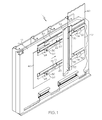
- FIG. 1 is a perspective view of a visible cladding attachment system according to one or more embodiments of the present invention.
- FIG. 2A is a horizontal cross-sectional view of a visible cladding attachment system according to one or more embodiments of the present invention.
- FIG. 2B is an exploded cross-sectional view of a visible cladding attachment system according to one or more embodiments of the present invention.
- FIG. 3 is a perspective view of a concealed cladding attachment system according to one or more embodiments of the present invention.
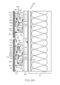
- FIG. 4A is a horizontal cross-sectional view of a concealed cladding attachment system according to one or more embodiments of the present invention.
- FIG. 4B is an exploded cross-sectional view of a concealed cladding attachment system according to one or more embodiments of the present invention.
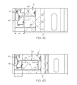
- FIG. 4C is a horizontal cross-sectional view of another concealed cladding attachment system according to one or more embodiments of the present invention.
- FIG. 4D is a horizontal cross-sectional view of yet another concealed cladding attachment system according to one or more embodiments of the present invention.
- a visible system 1 for fastening laminate panels 40 onto a building wall 10 is provided.
- this system 1 is considered a visible cladding attachment system, because the cladding fastener component(s) 32 are not hidden behind the laminate panels 40 .
- the building wall 10 may comprise many suitable structures familiar to one of ordinary skill in the art, such as a stud wall, exterior sheathing, a jam flashing membrane, a water resistive barrier, insulation, or any other building or foundation structure.
- the system 1 comprises at least one laminate panel support beam 20 , 25 mounted onto the building wall 10 , wherein the laminate panel support beam 20 , 25 comprises at least one track 24 .
- the laminate panel support beam 20 may be mounted directly onto the building wall 10 or may be coupled to an additional mounting structure (not shown) mounted on the building wall 10 .
- the laminate panel support beam 20 , 25 could be positioned vertically or diagonally if required by the structure and/or contours of the building wall 10 .
- the laminate panel support beam 20 may comprise two spaced parallel tracks 24 .
- the laminate panel support beam 20 may define a W-shape configuration wherein the tracks 24 constitute raised portions of the laminate panel support beam 20 , and the portion between the tracks 24 is a non-raised beam 23 that abuts a building wall 10 .
- the laminate panel support beam 20 of FIGS. 1 , 2 A-B may be mounted onto the building wall 10 via one or more fasteners 22 .
- Many fasteners are contemplated herein, for example, screws, bolts, nails, or combinations thereof.
- the fasteners 22 may comprise any suitable rigid material, for example, metals or metal alloys such as stainless steel, aluminum, or combinations thereof.
- the laminate panel support beam 25 may comprise one track 24 .
- the laminate panel support beam 25 may define a J-shape configuration wherein the track 24 is a raised portion of the laminate panel support beam 25 .
- the nonraised portion adjacent the track 24 contacts the building wall 10 , and is fastened to the building wall 10 with a fastener 22 .
- the laminate panel support beam 25 of FIG. 1 may be mounted onto the building wall 10 via one or more fasteners 22 .
- the one track laminate panel support beam 25 may be mounted on the building wall 10 proximate a two track laminate panel support beam 20 . While the depicted laminate panel support beams 20 and 25 are depicted as having one or two tracks and a J-shaped or W-shaped geometry, other structures and configurations are contemplated herein.
- the system 1 may also comprise at least one secondary support beam 50 oriented generally perpendicular to the laminate panel support beam 20 , 25 and mounted to at least one laminate panel support beam 20 , 25 . While the present discussion centers on secondary support beams 50 having a vertical configuration, is it contemplated that the secondary support beam 50 could be positioned horizontally or diagonally if required by the structure and/or contours of the building wall 10 . As shown in the embodiment of FIG. 1 , the secondary support beam 50 may be mounted to two laminate panel support beams 20 , 25 . It is also alternatively contemplated that the secondary support beam 50 may be coupled to less than two or more than two laminate panel support beams 20 , 25 .
- the secondary support beam 50 may also define various structural shapes and structural profiles. As shown in the embodiment of FIG. 1 , the secondary support beam 50 may comprise a pair of parallel raised beams 52 connected by a nonraised beam 53 disposed therebetween. As an alternative to this raised/nonraised profile, other embodiments may include a flat profile.
- the system 1 may also comprise at least one sliding clip 30 that is configured for attaching laminate panels 40 to the laminate panel support beams 20 , 25 .
- the sliding clips 30 may be slidingly coupled to track 24 , and are also attached to one or more laminate panels 40 , which are moveable with the sliding clips 30 .
- the system 1 may comprise two sliding clips 30 slidingly coupled to the two spaced tracks 24 of the two track laminate panel support beam 20 , as well as a sliding clip 30 slidingly coupled to the one track laminate panel support beam 25 . While the FIGS depict only one sliding clip 30 per track, it is contemplated to have multiple sliding clips 30 on each track 24 .
- the two track laminate panel support beam 20 may comprise two laminate panels 40 coupled thereto.
- the laminate panel 40 may be coupled at one end to a sliding clip 30 attached to a track on the two track lateral support beam 20 , and coupled at an opposite end to a sliding clip 30 on the one track laminate panel support beam 25 .
- the laminate panel 40 may be coupled to the sliding clip 30 via a fastening component 32 .
- the fastening component 32 is a bolt, a screw, or any other suitable fastener.
- the fastening component 32 may comprise a rigid material, for example, aluminum, stainless steel, or combinations thereof.
- the sliding clip(s) 30 may first be moved along the track(s) 24 to the desired position on the laminate panel support beam 20 , 25 , at which point, the laminate panel 40 is then attached to the sliding clip 30 .
- the sliding clip(s) 30 is first attached to the laminate panel 40 , then the sliding clip(s) 30 and attached laminate panel 40 may be slidingly moved along the track(s) 24 to the desired position on the laminate panel support beams 20 , 25 .
- the laminate panel 40 may be coupled to one or more of the sliding clips 30 before or after the sliding clips 30 are coupled to the tracks 24 of the laminate panel support beam 20 .
- the laminate panel 40 may then be secured to the secondary support beam 50 by means of a fastener 55 .
- the fastening component 55 may comprise a bolt, screw, or another suitable fastening component known to one of ordinary skill in the art. Without being bound by theory, the sliding functionality of the track 24 and clip 30 assembly enables the laminate panel 40 to be quickly attached to the facade of a building, or quickly removed, thereby reducing labor costs.
- the laminate panel 40 may be a phenolic resin based material.
- a suitable commercial embodiment for the laminate panel 40 is the VIVIXTM laminate produced by Formica®.
- the laminate panel support beam 20 , the sliding clip 30 , and the secondary support beam 50 may all comprise rigid support material, for example, a metal, a metal alloy, or combinations thereof. In exemplary embodiments, these rigid support materials may be selected from the group consisting of aluminum, stainless steel, or combinations thereof.
- the system 1 may also comprise a joint closure 60 disposed between sliding clips 30 on adjacent yet separated laminate panels 40 .
- the joint closure 60 is positioned to block the opening between the adjacent yet separated panels 40 .
- the joint closure 60 defines a C-shape adapted for the joint closure 60 to fit snugly between a pair of sliding clips 30 ; however other geometries are contemplated herein. While many materials are contemplated for the joint closure 60 , the joint closure 60 may comprise a rigid metal material such as aluminum or stainless steel.
- a concealed cladding attachment system 100 for fastening laminate panels 40 onto a building wall 10 is provided.
- this system 100 is considered a concealed cladding attachment system, because the support attachments are disposed behind the laminate panels 40 .
- the system 100 may comprise at least two wall brackets 130 horizontally spaced apart and attached to vertical beams 120 supported by the building wall 10 as shown in FIGS. 3 , 4 A, and 4 B, or mounted directly to the building wall 10 as shown in FIGS. 4C and 4D .
- the vertical beams 120 may be mounted onto the building wall 10 via a fastener 122 (e.g., a bolt, a screw, etc).
- wall bracket 130 may define an L-shaped cross-sectional profile comprising a vertical portion 137 attached to vertical beams 120 and a horizontal portion 132 extending perpendicularly from the bottom of the vertical portion 137 .
- the vertical portion 137 is attached to the vertical beams 120 via fasteners 131 , such as screws or bolts.
- the horizontal portion 132 of the wall bracket 130 is configured to extend the distance of a cavity 80 between the laminate panel 40 and the vertical beams 120 . As shown, the cavity 80 enables water drainage and air flow 90 in the concealed cladding attachment system 100 , or the visible cladding attachment system 1 .
- the vertical portion 137 is attached to an outer surface of a building wall 10 ; however, the wall bracket 130 comprises a horizontal portion 132 and/or a horizontal arm 133 that extends behind the vertical portion 137 and at least partially through a building wall 10 or insulation 11 .
- the wall bracket 130 may comprise a pair of spaced parallel vertical portions 137 a , 137 b .
- one of the vertical portions 137 b may be disposed inside the insulation 11 of the building wall 10 , whereas the other vertical portion 137 a may contact a surface of the building wall 10 .
- the horizontal portion 132 of the wall bracket is parallel to the horizontal arm 133 of the upper attachment component 134 .
- the horizontal portion 132 and the horizontal arm 133 extend perpendicular between the vertical portions 137 a and 137 b .
- the horizontal portion 132 and the horizontal arm 133 also extend beyond the distance 95 between the parallel vertical portions 137 a , 137 b .
- the horizontal portion 132 and the horizontal arm 133 may extend the length of the insulation 11 .
- the wall bracket 130 may comprise an upper attachment component 134 and a lower attachment component 136 for coupling with the intermediate connector 140 , as described in detail below.
- the lower attachment component 136 is attached to a horizontal arm 138 extending from the vertical portion 137 at a position above and parallel to the horizontal portion 132 of the wall bracket 130 .
- the lower attachment component 136 may be a protrusion configured to interlock with a corresponding protrusion of the lower coupling mechanism 144 of the intermediate connector 140 .
- the upper attachment component 134 may comprise a hook insertable into a receptacle, 142 , i.e., the upper coupling mechanism 142 as described in further detail below. As shown in FIGS.
- the hook of the upper attachment component 134 is attached to another horizontal arm 133 extending from the vertical portion 137 of the wall bracket 130 .
- Various other suitable structural components are contemplated for the upper attachment component 134 and the lower attachment component 136 .
- the system 100 also comprises at least one intermediate connector 140 coupled to the wall bracket 130 .
- the intermediate connector 140 comprises an upper coupling mechanism 142 configured to be coupled with the upper attachment component 134 of the wall bracket 130 .
- the intermediate connector 140 may matingly couple with the upper attachment component 134 of the wall bracket 130 .
- the upper coupling mechanism 142 may comprise a receptacle 142 that receives the hook 134 of the wall bracket 130 .
- the intermediate connector 140 also comprises a lower coupling mechanism 144 configured to couple with the lower attachment component 136 of the wall bracket 130 .
- the lower coupling mechanism may interlockingly couple with the lower attachment component 136 .
- the lower attachment component 136 of the intermediate connector 140 is a protrusion, which causes the lower attachment component 136 of the wall bracket 130 to deflect inwardly to facilitate the interlocking coupling arrangement.
- the intermediate connector 140 When attaching the intermediate connector 140 to the wall bracket 130 , the intermediate connector 140 is rotated such that the receptacle 142 attaches to the hook 134 , then the intermediate connector 140 is further rotated such that the lower coupling mechanism 144 (e.g., the protrusion 144 ) deflects the lower attachment component 136 (e.g., the protrusion 136 ) inwardly.
- the lower coupling mechanism 144 e.g., the protrusion 144
- the system 100 may also comprise a bumper 135 or extension coupled to the horizontal arm 133 of the wall bracket 130 , which is configured to engage an inward section 143 of the intermediate connector 140 to further secure the intermediate connector 140 on the wall bracket 130 .
- the intermediate connector 140 also comprises an intermediate hanger member 146 used for coupling with the laminate panel hanger member 151 of the hanger clip 150 .
- the hanger clips 150 which join the laminate panel 40 to the intermediate connector 140 , utilize their respective laminate panel hanger member 151 to matingly couple with the intermediate hanger member 146 of the intermediate connector 140 .
- the intermediate hanger member 146 is nested within the laminate panel hanger member 151 .
- the hanger clips 150 may be coupled to the laminate panels 40 prior to the attachment of the hanger clip(s) 150 to the intermediate connector(s) 140 .
- the hanger clip(s) 150 may be attached to the intermediate connector(s) 140 prior to the laminate panels 40 being attached to the hanger clips 150 .
- the hanger clip 150 may be attached to the laminate panel 40 via any suitable fastener 155 , such as a screw or bolt.
- the hanger clip 150 comprises additional components which ensure that the hanger clip 150 is securely attached to the intermediate connector 140 .
- the hanger clip 150 may comprise an adjustable bolt 156 , which may be adjusted to engage the upper surface 145 of the intermediate connector 140 to stabilize the hanger clip 150 on the intermediate connector 140 .
- the hanger clip 150 is manufactured and packaged with the adjustable bolt 156 and nut 157 attached, wherein the nut 157 is disposed in a slot 152 of the hanger clip 150 . Packaging the adjustable bolt 156 and nut 157 with the hanger clip 150 eliminates the need for the consumer to purchase a separate fastener to secure the hanger clip 150 to the intermediate connector 140 .
- the hanger clip 150 may also comprise a flexible cushioning component 160 , which engages a surface 141 of the intermediate connector 140 to stabilize the hanger clip 150 on the intermediate connector 140 .
- the flexible cushioning component 160 which may be embedded in the hanger clip 150 , has a flexible tip, which deflects upon engaging surface 141 of the intermediate connector 140 .
- the flexible cushioning component 160 helps prevent the intermediate connector 140 or hanger clip 150 from moving relative to each other, thereby further securing the hanger clip 150 on the intermediate connector 140 .
- the flexible cushioning component 160 may comprise any suitable flexible material, for example, a flexible polymeric nondegradable material such as polyurethane, SantopreneTM, other thermoplastic elastomers, or combinations thereof
- the hanger clip 150 may also comprises recessed reservoir portions 153 , 154 operable to collect condensed water.
- the recessed reservoir portions 153 , 154 may be sloped to facilitate the removal of condensate present on the recessed reservoir portions 153 , 154 of the hanging clip 150 .
- the concealed cladding attachment system 100 may also comprise a joint closure 170 coupled to the wall bracket 130 via fastener 174 .
- the joint closure 170 is configured to block the opening between adjacent yet separated laminate panels 40 .
- the joint closure 60 comprises a lower lip 172 operable to collect and remove water.
- the term “substantially” is utilized herein to represent the inherent degree of uncertainty that may be attributed to any quantitative comparison, value, measurement, or other representation.
- the term “substantially” is also utilized herein to represent the degree by which a quantitative representation may vary from a stated reference without resulting in a change in the basic function of the subject matter at issue.
Abstract
Visible and concealed cladding systems used for attaching laminate panels to building structures are provided. The visible cladding systems comprise tracks and sliding clips to slide the laminate panel into the desired location on the building wall. The concealed cladding systems comprise hanger elements to attach a laminate panel to the building wall.
Description
This application is filed as a divisional of U.S. application Ser. No. 13/700,516 filed on Feb. 6, 2013, which is a national stage entry of PCT/US2011/03781 filed on May 25, 2011, which claims priority to U.S. Provisional Application Ser. No. 61/349,353 filed May 28, 2010.
The present invention relates generally to laminate panels (also called facade cladding panels) to be applied to the facade of buildings, and specifically relates to cladding systems and methods for affixing the laminate panels to building facades more efficiently and with less cost.
According to one embodiment, a visible cladding system for attaching laminate panels onto a building wall is provided. The visible cladding system comprises at least one laminate panel support beam to be mounted onto a building wall, wherein the laminate panel support beam comprises at least one track. The visible cladding system also comprises at least one secondary support beam mounted to the at least one laminate panel support beam, at least one sliding clip slidingly coupled to at least one track, and at least one laminate panel coupled to at least one sliding clip and thereby slidable along the track, wherein the laminate panel is configured to be fastened to the secondary support beam.
According to yet another embodiment, a concealed cladding system configured for attaching laminate panels onto a building wall is provided. The system comprises at least two wall brackets horizontally spaced apart, wherein each wall bracket comprises an upper attachment component and a lower attachment component. The system also comprises at least one intermediate connector coupled to the wall brackets, wherein the intermediate connector comprises an upper coupling mechanism, a lower coupling mechanism, and a hanger member. The upper coupling mechanism of the intermediate connector is coupled with the upper attachment component of the wall brackets, and the lower attachment component of the intermediate connector is coupled with the upper attachment component of the wall bracket. The concealed cladding system also comprises at least one hanger clip having a laminate panel hanger member coupled with the hanger member of the intermediate connector; and a laminate panel fastened to at least one of the hanger clips.
The features and advantages of the present invention will become apparent from the following description and the accompanying drawings.
The following detailed description of the embodiments of the present invention can be best understood when read in conjunction with the following drawings, where like structure is indicated with like reference numerals.
Referring to FIGS. 1 , 2A and 2B, a visible system 1 for fastening laminate panels 40 onto a building wall 10 is provided. As stated above, this system 1 is considered a visible cladding attachment system, because the cladding fastener component(s) 32 are not hidden behind the laminate panels 40. As used herein, the building wall 10 may comprise many suitable structures familiar to one of ordinary skill in the art, such as a stud wall, exterior sheathing, a jam flashing membrane, a water resistive barrier, insulation, or any other building or foundation structure.
Referring again to FIGS. 1 , 2A and 2B, the system 1 comprises at least one laminate panel support beam 20, 25 mounted onto the building wall 10, wherein the laminate panel support beam 20, 25 comprises at least one track 24. In the embodiment of FIGS. 1 , 2A and 2B, the laminate panel support beam 20 may be mounted directly onto the building wall 10 or may be coupled to an additional mounting structure (not shown) mounted on the building wall 10. Also, while the present discussion centers on a laminate panel support beam 20, 25 having a horizontal configuration, is it contemplated that the laminate panel support beam 20, 25 could be positioned vertically or diagonally if required by the structure and/or contours of the building wall 10.
Referring again to the embodiment shown in FIGS. 1 , 2A-B, the laminate panel support beam 20 may comprise two spaced parallel tracks 24. In this embodiment, the laminate panel support beam 20 may define a W-shape configuration wherein the tracks 24 constitute raised portions of the laminate panel support beam 20, and the portion between the tracks 24 is a non-raised beam 23 that abuts a building wall 10. As shown, the laminate panel support beam 20 of FIGS. 1 , 2A-B may be mounted onto the building wall 10 via one or more fasteners 22. Many fasteners are contemplated herein, for example, screws, bolts, nails, or combinations thereof. The fasteners 22 may comprise any suitable rigid material, for example, metals or metal alloys such as stainless steel, aluminum, or combinations thereof.
In an alternative embodiment as shown in FIG. 1 , the laminate panel support beam 25 may comprise one track 24. In this embodiment, the laminate panel support beam 25 may define a J-shape configuration wherein the track 24 is a raised portion of the laminate panel support beam 25. In the J-shape configuration, the nonraised portion adjacent the track 24 contacts the building wall 10, and is fastened to the building wall 10 with a fastener 22. As shown in FIG. 1 , the laminate panel support beam 25 of FIG. 1 may be mounted onto the building wall 10 via one or more fasteners 22. Further as shown, the one track laminate panel support beam 25 may be mounted on the building wall 10 proximate a two track laminate panel support beam 20. While the depicted laminate panel support beams 20 and 25 are depicted as having one or two tracks and a J-shaped or W-shaped geometry, other structures and configurations are contemplated herein.
Referring to FIG. 1 , the system 1 may also comprise at least one secondary support beam 50 oriented generally perpendicular to the laminate panel support beam 20, 25 and mounted to at least one laminate panel support beam 20, 25. While the present discussion centers on secondary support beams 50 having a vertical configuration, is it contemplated that the secondary support beam 50 could be positioned horizontally or diagonally if required by the structure and/or contours of the building wall 10. As shown in the embodiment of FIG. 1 , the secondary support beam 50 may be mounted to two laminate panel support beams 20, 25. It is also alternatively contemplated that the secondary support beam 50 may be coupled to less than two or more than two laminate panel support beams 20, 25. Moreover, it is also contemplated that the secondary support beam 50 may also define various structural shapes and structural profiles. As shown in the embodiment of FIG. 1 , the secondary support beam 50 may comprise a pair of parallel raised beams 52 connected by a nonraised beam 53 disposed therebetween. As an alternative to this raised/nonraised profile, other embodiments may include a flat profile.
Referring again to FIGS. 1 , 2A and 2B, the system 1 may also comprise at least one sliding clip 30 that is configured for attaching laminate panels 40 to the laminate panel support beams 20, 25. The sliding clips 30 may be slidingly coupled to track 24, and are also attached to one or more laminate panels 40, which are moveable with the sliding clips 30. As shown in FIGS. 1 , 2A and 2B, the system 1 may comprise two sliding clips 30 slidingly coupled to the two spaced tracks 24 of the two track laminate panel support beam 20, as well as a sliding clip 30 slidingly coupled to the one track laminate panel support beam 25. While the FIGS depict only one sliding clip 30 per track, it is contemplated to have multiple sliding clips 30 on each track 24.
Referring yet again to FIGS. 1 , 2A, and 2B, the two track laminate panel support beam 20 may comprise two laminate panels 40 coupled thereto. In another embodiment as shown, the laminate panel 40 may be coupled at one end to a sliding clip 30 attached to a track on the two track lateral support beam 20, and coupled at an opposite end to a sliding clip 30 on the one track laminate panel support beam 25. The laminate panel 40 may be coupled to the sliding clip 30 via a fastening component 32. The fastening component 32 is a bolt, a screw, or any other suitable fastener. The fastening component 32 may comprise a rigid material, for example, aluminum, stainless steel, or combinations thereof.
When mounting the laminate panel 40 onto the laminate panel support beam 20, various assembly sequences are contemplated. For example, the sliding clip(s) 30 may first be moved along the track(s) 24 to the desired position on the laminate panel support beam 20, 25, at which point, the laminate panel 40 is then attached to the sliding clip 30. Alternatively as shown in FIG. 1 , the sliding clip(s) 30 is first attached to the laminate panel 40, then the sliding clip(s) 30 and attached laminate panel 40 may be slidingly moved along the track(s) 24 to the desired position on the laminate panel support beams 20, 25. In essence, the laminate panel 40 may be coupled to one or more of the sliding clips 30 before or after the sliding clips 30 are coupled to the tracks 24 of the laminate panel support beam 20. After the laminate panel 40 is positioned at the desired position on the building wall 10, the laminate panel 40 may then be secured to the secondary support beam 50 by means of a fastener 55. Like the other fasteners described above, the fastening component 55 may comprise a bolt, screw, or another suitable fastening component known to one of ordinary skill in the art. Without being bound by theory, the sliding functionality of the track 24 and clip 30 assembly enables the laminate panel 40 to be quickly attached to the facade of a building, or quickly removed, thereby reducing labor costs.
Various materials and compositions are contemplated for the visible system 1. In one embodiment, the laminate panel 40 may be a phenolic resin based material. A suitable commercial embodiment for the laminate panel 40 is the VIVIX™ laminate produced by Formica®. The laminate panel support beam 20, the sliding clip 30, and the secondary support beam 50 may all comprise rigid support material, for example, a metal, a metal alloy, or combinations thereof. In exemplary embodiments, these rigid support materials may be selected from the group consisting of aluminum, stainless steel, or combinations thereof.
In a further embodiment as shown in FIGS. 2A-B , the system 1 may also comprise a joint closure 60 disposed between sliding clips 30 on adjacent yet separated laminate panels 40. The joint closure 60 is positioned to block the opening between the adjacent yet separated panels 40. The joint closure 60, as shown in FIG. 2A , defines a C-shape adapted for the joint closure 60 to fit snugly between a pair of sliding clips 30; however other geometries are contemplated herein. While many materials are contemplated for the joint closure 60, the joint closure 60 may comprise a rigid metal material such as aluminum or stainless steel.
Referring to FIGS. 3 and 4A-4D, a concealed cladding attachment system 100 for fastening laminate panels 40 onto a building wall 10 is provided. In contrast to the visible system 1, this system 100 is considered a concealed cladding attachment system, because the support attachments are disposed behind the laminate panels 40. Referring to FIG. 3 , the system 100 may comprise at least two wall brackets 130 horizontally spaced apart and attached to vertical beams 120 supported by the building wall 10 as shown in FIGS. 3 , 4A, and 4B, or mounted directly to the building wall 10 as shown in FIGS. 4C and 4D . As shown in FIGS. 4A and 4B , the vertical beams 120 may be mounted onto the building wall 10 via a fastener 122 (e.g., a bolt, a screw, etc).
Various geometries and structures are contemplated for the wall bracket 130. As shown in FIGS. 4A-B , wall bracket 30 may define an L-shaped cross-sectional profile comprising a vertical portion 137 attached to vertical beams 120 and a horizontal portion 132 extending perpendicularly from the bottom of the vertical portion 137. The vertical portion 137 is attached to the vertical beams 120 via fasteners 131, such as screws or bolts. In one embodiment, the horizontal portion 132 of the wall bracket 130 is configured to extend the distance of a cavity 80 between the laminate panel 40 and the vertical beams 120. As shown, the cavity 80 enables water drainage and air flow 90 in the concealed cladding attachment system 100, or the visible cladding attachment system 1. As an alternative to the L-configuration of FIGS. 4A and 4B , referring to FIG. 4C , the vertical portion 137 is attached to an outer surface of a building wall 10; however, the wall bracket 130 comprises a horizontal portion 132 and/or a horizontal arm 133 that extends behind the vertical portion 137 and at least partially through a building wall 10 or insulation 11.
Moreover, as shown in FIG. 4D , the wall bracket 130 may comprise a pair of spaced parallel vertical portions 137 a, 137 b. As shown in the embodiment of FIG. 4D , one of the vertical portions 137 b may be disposed inside the insulation 11 of the building wall 10, whereas the other vertical portion 137 a may contact a surface of the building wall 10. In this embodiment, the horizontal portion 132 of the wall bracket is parallel to the horizontal arm 133 of the upper attachment component 134. As shown, the horizontal portion 132 and the horizontal arm 133 extend perpendicular between the vertical portions 137 a and 137 b. Moreover as shown in FIG. 4D , the horizontal portion 132 and the horizontal arm 133 also extend beyond the distance 95 between the parallel vertical portions 137 a, 137 b. For example, the horizontal portion 132 and the horizontal arm 133 may extend the length of the insulation 11.
Further as shown in FIGS. 4A-B , the wall bracket 130 may comprise an upper attachment component 134 and a lower attachment component 136 for coupling with the intermediate connector 140, as described in detail below. The lower attachment component 136 is attached to a horizontal arm 138 extending from the vertical portion 137 at a position above and parallel to the horizontal portion 132 of the wall bracket 130. In one embodiment, the lower attachment component 136 may be a protrusion configured to interlock with a corresponding protrusion of the lower coupling mechanism 144 of the intermediate connector 140. The upper attachment component 134 may comprise a hook insertable into a receptacle, 142, i.e., the upper coupling mechanism 142 as described in further detail below. As shown in FIGS. 4A and 4B , the hook of the upper attachment component 134 is attached to another horizontal arm 133 extending from the vertical portion 137 of the wall bracket 130. Various other suitable structural components are contemplated for the upper attachment component 134 and the lower attachment component 136.
Referring again to FIGS. 3 , and 4A-4D, the system 100 also comprises at least one intermediate connector 140 coupled to the wall bracket 130. The intermediate connector 140 comprises an upper coupling mechanism 142 configured to be coupled with the upper attachment component 134 of the wall bracket 130. In one embodiment, the intermediate connector 140 may matingly couple with the upper attachment component 134 of the wall bracket 130. For example as shown in FIGS. 4A-4D , the upper coupling mechanism 142 may comprise a receptacle 142 that receives the hook 134 of the wall bracket 130.
As shown in FIGS. 3 and 4B , the intermediate connector 140 also comprises a lower coupling mechanism 144 configured to couple with the lower attachment component 136 of the wall bracket 130. In one embodiment, the lower coupling mechanism may interlockingly couple with the lower attachment component 136. As shown, the lower attachment component 136 of the intermediate connector 140 is a protrusion, which causes the lower attachment component 136 of the wall bracket 130 to deflect inwardly to facilitate the interlocking coupling arrangement. When attaching the intermediate connector 140 to the wall bracket 130, the intermediate connector 140 is rotated such that the receptacle 142 attaches to the hook 134, then the intermediate connector 140 is further rotated such that the lower coupling mechanism 144 (e.g., the protrusion 144) deflects the lower attachment component 136 (e.g., the protrusion 136) inwardly.
Having multiple connections between the wall bracket 130 and the intermediate connector 140 as described above helps ensure the wall bracket 130 is secured to the intermediate connector 140. That being said, the system 100 may also comprise a bumper 135 or extension coupled to the horizontal arm 133 of the wall bracket 130, which is configured to engage an inward section 143 of the intermediate connector 140 to further secure the intermediate connector 140 on the wall bracket 130.
Further as shown in FIGS. 3 , 4A, and 4B, the intermediate connector 140 also comprises an intermediate hanger member 146 used for coupling with the laminate panel hanger member 151 of the hanger clip 150. Referring to FIGS. 3 , and 4A-B, the hanger clips 150, which join the laminate panel 40 to the intermediate connector 140, utilize their respective laminate panel hanger member 151 to matingly couple with the intermediate hanger member 146 of the intermediate connector 140. Specifically as shown, the intermediate hanger member 146 is nested within the laminate panel hanger member 151.
When attaching the laminate panel 40 in the system 100 of the present invention, various assembly sequences are contemplated. Specifically, the hanger clips 150 may be coupled to the laminate panels 40 prior to the attachment of the hanger clip(s) 150 to the intermediate connector(s) 140. In an alternative embodiment, it is contemplated that the hanger clip(s) 150 may be attached to the intermediate connector(s) 140 prior to the laminate panels 40 being attached to the hanger clips 150. The hanger clip 150 may be attached to the laminate panel 40 via any suitable fastener 155, such as a screw or bolt.
The hanger clip 150 comprises additional components which ensure that the hanger clip 150 is securely attached to the intermediate connector 140. As shown in FIGS. 4A-4B , the hanger clip 150 may comprise an adjustable bolt 156, which may be adjusted to engage the upper surface 145 of the intermediate connector 140 to stabilize the hanger clip 150 on the intermediate connector 140. In a specific embodiment, the hanger clip 150 is manufactured and packaged with the adjustable bolt 156 and nut 157 attached, wherein the nut 157 is disposed in a slot 152 of the hanger clip 150. Packaging the adjustable bolt 156 and nut 157 with the hanger clip 150 eliminates the need for the consumer to purchase a separate fastener to secure the hanger clip 150 to the intermediate connector 140.
In further embodiments as shown in FIGS. 4A-B , the hanger clip 150 may also comprise a flexible cushioning component 160, which engages a surface 141 of the intermediate connector 140 to stabilize the hanger clip 150 on the intermediate connector 140. As shown, the flexible cushioning component 160, which may be embedded in the hanger clip 150, has a flexible tip, which deflects upon engaging surface 141 of the intermediate connector 140. By engaging the intermediate connector 140, the flexible cushioning component 160 helps prevent the intermediate connector 140 or hanger clip 150 from moving relative to each other, thereby further securing the hanger clip 150 on the intermediate connector 140. The flexible cushioning component 160 may comprise any suitable flexible material, for example, a flexible polymeric nondegradable material such as polyurethane, Santoprene™, other thermoplastic elastomers, or combinations thereof
In further embodiments as shown in FIGS. 4A-B , the hanger clip 150 may also comprises recessed reservoir portions 153, 154 operable to collect condensed water. The recessed reservoir portions 153, 154 may be sloped to facilitate the removal of condensate present on the recessed reservoir portions 153, 154 of the hanging clip 150. Similar to the visible cladding system 1, the concealed cladding attachment system 100 may also comprise a joint closure 170 coupled to the wall bracket 130 via fastener 174. As shown in FIGS. 4A-B , the joint closure 170 is configured to block the opening between adjacent yet separated laminate panels 40. Similar to the recessed reservoir portions 153, 154 of the hanger clip 150, the joint closure 60 comprises a lower lip 172 operable to collect and remove water.
Moreover, it is contemplated to use various additional structural components for the cladding systems depending on the needs of the builder. For example, pieces with different shapes and curvatures may be specifically developed for the contours or corners of the building wall 10.
It is further noted that terms like “preferably,” “generally”, “commonly,” and “typically” are not utilized herein to limit the scope of the claimed invention or to imply that certain features are critical, essential, or even important to the structure or function of the claimed invention. Rather, these terms are merely intended to highlight alternative or additional features that may or may not be utilized in a particular embodiment of the present invention.
For the purposes of describing and defining the present invention it is additionally noted that the term “substantially” is utilized herein to represent the inherent degree of uncertainty that may be attributed to any quantitative comparison, value, measurement, or other representation. The term “substantially” is also utilized herein to represent the degree by which a quantitative representation may vary from a stated reference without resulting in a change in the basic function of the subject matter at issue.
Having described the invention in detail and by reference to specific embodiments thereof, it will be apparent that modifications and variations are possible without departing from the scope of the invention defined in the appended claims. More specifically, although some aspects of the present invention are identified herein as preferred or particularly advantageous, it is contemplated that the present invention is not necessarily limited to these preferred aspects of the invention.
Claims (5)
1. A visible cladding system for attaching laminate panels onto a building wall comprising:
at least one laminate panel support beam configured to be mounted onto the building wall, wherein the laminate panel support beam comprises two spaced parallel tracks on two spaced raised portions of the laminate panel support beam, and a non-raised beam integral and extending between the two spaced raised portions, wherein each track comprises two recessed slots disposed on opposite edges of each track;
at least one secondary support beam mounted to the at least one laminate panel support beam;
at least one sliding clip slidingly coupled to the at least one track wherein the sliding clip comprises two inserts configured to respectively fit within the two recessed slots of the track and slidingly move therein; and
at least one laminate panel coupled to the at least one sliding clip and thereby slidable along the track, wherein the laminate panel is configured to be fastened to the secondary support beam.
2. The system of claim 1 wherein the secondary support beam is coupled to a pair of laminate panel support beams, and wherein the laminate panel is coupled to the pair of laminate panel support beams and fastened to the secondary support beam.
3. The system of claim 1 wherein the laminate panel support beam is mountable onto the building wall via one or more fasteners, the fasteners being selected from the group consisting of screws, bolts, nails, or combinations thereof.
4. The system of claim 1 wherein the system comprises two spaced laminate panel support beams, wherein the laminate panel is attached to clips of the two spaced laminate panel support beams.
5. The system of claim 1 wherein each laminate panel support beam may be attached to two laminate panels via two sliding clips therebetween.
Priority Applications (1)
| Application Number | Priority Date | Filing Date | Title |
|---|---|---|---|
| US14/288,430 US8991127B2 (en) | 2010-05-28 | 2014-05-28 | Cladding system for building laminates |
Applications Claiming Priority (4)
| Application Number | Priority Date | Filing Date | Title |
|---|---|---|---|
| US34935310P | 2010-05-28 | 2010-05-28 | |
| PCT/US2011/037871 WO2011150035A2 (en) | 2010-05-28 | 2011-05-25 | Cladding system for building laminates |
| US201313700516A | 2013-02-06 | 2013-02-06 | |
| US14/288,430 US8991127B2 (en) | 2010-05-28 | 2014-05-28 | Cladding system for building laminates |
Related Parent Applications (2)
| Application Number | Title | Priority Date | Filing Date |
|---|---|---|---|
| US13/700,516 Division US8769901B2 (en) | 2010-05-28 | 2011-05-25 | Cladding system for building laminates |
| PCT/US2011/037871 Division WO2011150035A2 (en) | 2010-05-28 | 2011-05-25 | Cladding system for building laminates |
Publications (2)
| Publication Number | Publication Date |
|---|---|
| US20140260042A1 US20140260042A1 (en) | 2014-09-18 |
| US8991127B2 true US8991127B2 (en) | 2015-03-31 |
Family
ID=44627162
Family Applications (2)
| Application Number | Title | Priority Date | Filing Date |
|---|---|---|---|
| US13/700,516 Active US8769901B2 (en) | 2010-05-28 | 2011-05-25 | Cladding system for building laminates |
| US14/288,430 Active US8991127B2 (en) | 2010-05-28 | 2014-05-28 | Cladding system for building laminates |
Family Applications Before (1)
| Application Number | Title | Priority Date | Filing Date |
|---|---|---|---|
| US13/700,516 Active US8769901B2 (en) | 2010-05-28 | 2011-05-25 | Cladding system for building laminates |
Country Status (6)
| Country | Link |
|---|---|
| US (2) | US8769901B2 (en) |
| EP (1) | EP2576939B1 (en) |
| CA (1) | CA2799496C (en) |
| ES (1) | ES2657612T3 (en) |
| NO (1) | NO2576939T3 (en) |
| WO (1) | WO2011150035A2 (en) |
Cited By (7)
| Publication number | Priority date | Publication date | Assignee | Title |
|---|---|---|---|---|
| US9359771B1 (en) * | 2015-06-01 | 2016-06-07 | Delforte Sales, Inc. | Removable highly secured wall panel mounting system |
| US10253507B1 (en) * | 2017-04-17 | 2019-04-09 | Henry H. Bilge | System for mounting wall panels to a wall |
| US10612574B1 (en) * | 2019-04-09 | 2020-04-07 | Joseph J. FORAL | Insulation retainer clip |
| US10787817B1 (en) | 2017-04-17 | 2020-09-29 | Henry H. Bilge | System for mounting adjustable covering panels to a wall |
| USD962048S1 (en) | 2019-04-30 | 2022-08-30 | Hunter Douglas Inc. | Coupling device for mounting tiles to a building |
| US11629506B1 (en) * | 2018-07-06 | 2023-04-18 | Associated Architectural Products, Inc. | Method and apparatus for a wall panel system |
| US11905713B2 (en) | 2019-04-30 | 2024-02-20 | Hunter Douglas Inc. | Coupling system for mounting tiles to a building |
Families Citing this family (56)
| Publication number | Priority date | Publication date | Assignee | Title |
|---|---|---|---|---|
| US9267295B2 (en) * | 2010-07-09 | 2016-02-23 | Matthew Mann | Suspension rails for panel veneer systems |
| US9091079B2 (en) | 2010-10-22 | 2015-07-28 | Laminators Incorporated | Panel mounting apparatus and system |
| US20130205695A1 (en) * | 2011-12-07 | 2013-08-15 | Brian Geofrey Newell | Access |
| GB2497796A (en) * | 2011-12-21 | 2013-06-26 | Hardie James Technology Ltd | Thermally Efficient Façade |
| DE102011056785A1 (en) * | 2011-12-21 | 2013-06-27 | Tilo Uhlig | Mounting arrangement for flat components, in particular for glass elements or solar modules |
| US20130269276A1 (en) * | 2012-04-12 | 2013-10-17 | Trespa International B.V. | System for mounting to a facade wall of a building |
| ITMI20120845A1 (en) * | 2012-05-16 | 2013-11-17 | Aliavis Srl | KIT AND METHOD FOR MOUNTING A SOLAR PANEL WITH A ROOF AND SOLAR PANEL |
| US20140020319A1 (en) * | 2012-07-17 | 2014-01-23 | Nicholas Vittorio Marchese | Exterior Panel System |
| US9957714B2 (en) * | 2012-12-03 | 2018-05-01 | Kingspan Holdings (Irl) Limited | Composite insulating and cladding panel |
| US9140007B2 (en) | 2013-04-23 | 2015-09-22 | MOTO Extrusions, Inc. | Rain screen framing system |
| US9140008B2 (en) * | 2013-04-23 | 2015-09-22 | MOTO Extrusions, Inc. | Multi-layered cladding frame system |
| US8910441B1 (en) * | 2013-06-18 | 2014-12-16 | Kenneth Hunter | Cladding attachment system to enable an exterior continuous insulation barrier |
| US8833017B1 (en) * | 2013-10-02 | 2014-09-16 | Rong-Jun Huang | Rapid hanging curtain wall unit for a wall assembling structure |
| US11371245B2 (en) | 2013-10-25 | 2022-06-28 | Mbrico, Llc | Tile and support structure |
| US10041254B2 (en) * | 2013-10-25 | 2018-08-07 | Mbrico, Llc | Tile and support structure |
| US10988931B1 (en) | 2013-10-25 | 2021-04-27 | Mbrico, Llc | Tile and support structure |
| US11199007B2 (en) | 2013-10-25 | 2021-12-14 | Mbrico, Llc | Tile and support structure |
| US9745739B2 (en) * | 2014-02-25 | 2017-08-29 | Breton Systems Llc | Wall construction method using injected urethane foam between the wall and autoclaved concrete (AAC) blocks |
| USD758835S1 (en) | 2014-06-28 | 2016-06-14 | Kingspan Insulated Panels, Inc. | Building panel connector |
| US9347225B2 (en) | 2014-06-28 | 2016-05-24 | Kingspan Insulated Panels, Inc. | Building panel connector |
| EP2982272A1 (en) * | 2014-08-07 | 2016-02-10 | Unifor S.p.A. | Extruded profile for a fitted panel and fitted panel comprising said extruded profile |
| US9598892B2 (en) | 2014-09-15 | 2017-03-21 | Gregory Header | Quick release cladding system for door, window, sloped and vertical glazing systems frames, and the like |
| WO2016061414A1 (en) * | 2014-10-15 | 2016-04-21 | Eclad Usa, Inc. | Undercut clip anchor system for cladding of materials |
| JP6456095B2 (en) * | 2014-10-17 | 2019-01-23 | トヨタホーム株式会社 | Building outer wall structure |
| CA2911010A1 (en) * | 2014-11-10 | 2016-05-10 | Bernard Ted Cullen | Insulating wall assembly with framing member supports partially embedded within rigid insulation panels |
| US9404270B2 (en) | 2014-11-17 | 2016-08-02 | West Tampa Glass Company | Panel and mounting system |
| US10066781B2 (en) * | 2015-04-15 | 2018-09-04 | Parasoleil | Architectural panel support |
| ES2586736B1 (en) * | 2015-04-15 | 2017-09-07 | Cupa Innovacion S.L.U. | VENTILATED FACADE |
| US20170020287A1 (en) * | 2015-04-24 | 2017-01-26 | Qtran, Inc. | Support bracket system |
| US9469999B1 (en) * | 2015-04-30 | 2016-10-18 | Wall Panel Systems, Inc. | Exterior wall panneling system |
| US9938725B2 (en) | 2015-05-04 | 2018-04-10 | Kingspan Insulated Panels, Inc. | Building panel |
| EP3298211A4 (en) * | 2015-05-21 | 2019-01-09 | Komproment Holding AF 2007 APS | Rail system |
| US10844609B2 (en) * | 2016-04-22 | 2020-11-24 | Jimmy Keith Yeary, JR. | Building rail system |
| PL232498B1 (en) * | 2016-06-10 | 2019-06-28 | Wido Profil Spolka Z Ograniczona Odpowiedzialnoscia | Non-anchor system for fixing panel cladding elements and method for fixing it |
| US10081941B2 (en) * | 2016-06-21 | 2018-09-25 | Fry Reglet Corporation | Wall cladding system and method |
| US11131091B2 (en) * | 2016-06-30 | 2021-09-28 | Knauf Gips Kg | Drywall construction system with spring rail |
| US10590644B2 (en) * | 2017-07-24 | 2020-03-17 | BŌK Modern LLC | Universal mounting system |
| US10550577B2 (en) * | 2017-08-16 | 2020-02-04 | Charbel Tannious Aboukhalil | Face mounting system |
| JP7053206B2 (en) * | 2017-09-29 | 2022-04-12 | ニチハ株式会社 | Fixtures and building wall structures |
| CN108019013B (en) * | 2017-11-10 | 2024-03-26 | 楼里外硬核科技(北京)有限公司 | Decoration heat preservation structure for building outer wall convex modeling |
| CA3082515A1 (en) * | 2017-11-17 | 2019-05-23 | Rockwool International A/S | Suspension system |
| EP3594427B1 (en) * | 2018-07-13 | 2023-09-06 | GFT Fassaden AG | System and method for fixing facade elements |
| EP3599332A1 (en) | 2018-07-25 | 2020-01-29 | Frederico Ferreira | Modular system for panel locomotion in building facades |
| WO2020061034A1 (en) * | 2018-09-19 | 2020-03-26 | Fiber Composites, LLC (dba Fiberon) | Siding clip |
| WO2020129113A1 (en) * | 2018-12-17 | 2020-06-25 | 株式会社ヒロコーポレーション | Tile panel support structure |
| WO2020181513A1 (en) * | 2019-03-13 | 2020-09-17 | 鞠楠 | Assembled light steel structure energy-saving composite wall |
| US10900239B1 (en) * | 2019-09-24 | 2021-01-26 | Henry H. Bilge | System for mounting wall panels to an existing wall |
| CN111236506B (en) * | 2020-01-20 | 2021-01-26 | 福建省兴岩建设集团有限公司 | Hang curtain futilely with short cantilever dry-hanging device |
| US11371240B1 (en) * | 2020-10-13 | 2022-06-28 | Joseph J. FORAL | Insulation retainer clip |
| US11519180B2 (en) * | 2021-03-11 | 2022-12-06 | Henry H. Bilge | System for mounting wall panels onto a wall or floor slabs |
| US11938086B2 (en) * | 2021-03-30 | 2024-03-26 | Ralph Lauterbach | Releasable locking system for vertical panels |
| KR102345056B1 (en) * | 2021-05-13 | 2021-12-29 | 노원훈 | Modular wall assembly using solenoid |
| ES1286749Y (en) | 2021-11-18 | 2022-05-09 | Sist Tecnicos Del Accesorio Y Componentes S L | DEVICE FOR FIXING VENTILATED FAÇADES |
| CN114737703A (en) * | 2022-06-14 | 2022-07-12 | 北京建工集团有限责任公司 | Unit type aluminum plate curtain wall system adaptable to any modeling and construction process thereof |
| US11933046B1 (en) * | 2022-07-14 | 2024-03-19 | Anthony Attalla | Stiff wall panel assembly for a building structure and associated method(s) |
| CA3224287A1 (en) * | 2022-07-26 | 2024-01-26 | Serkan Sabri Bayram | A ventilated facade cladding system |
Citations (145)
| Publication number | Priority date | Publication date | Assignee | Title |
|---|---|---|---|---|
| US3412515A (en) | 1966-05-06 | 1968-11-26 | Fabrication D Isolants Et Reve | Assembly for installing prefabricated wall panels |
| US4070835A (en) | 1976-08-09 | 1978-01-31 | Safama | Device intended for the hooking of panels on a wall in order to constitute a covering on this wall |
| EP0067970A1 (en) | 1981-06-19 | 1982-12-29 | Peter Dipl.-Ing. Wagner | Fastening device for facing elements on outer wall |
| US4516373A (en) * | 1981-10-26 | 1985-05-14 | Yoshinori Osawa | Apparatus for tile-setting |
| CH659679A5 (en) | 1986-04-09 | 1987-02-13 | August Braendli | Retaining device for facade claddings or internal claddings of walls and internal claddings or external claddings of ceilings |
| EP0286052A2 (en) | 1987-04-09 | 1988-10-12 | Ward Building Systems Limited | Building cladding system |
| EP0290426A2 (en) | 1987-05-08 | 1988-11-09 | Heinz Eggert | Cladding for building walls |
| EP0304338A1 (en) | 1987-08-21 | 1989-02-22 | Cormid Limited | Fixing and coupling of panels and cladding |
| EP0311738A1 (en) | 1987-10-16 | 1989-04-19 | Ward Building Systems Limited | Building cladding system |
| US4840004A (en) | 1988-07-21 | 1989-06-20 | Ting Raymond M L | Externally drained wall joint design |
| EP0337066A1 (en) | 1988-03-23 | 1989-10-18 | DETEC Fertigung GmbH | Anchoring strap |
| EP0345661A1 (en) | 1988-06-04 | 1989-12-13 | Walter Dipl.-Ing. Haase | Suspended coffer element |
| EP0360001A1 (en) | 1988-09-22 | 1990-03-28 | Bitra AG | Device for fixing panels to a wall, particularly ceramic panels |
| EP0391737A1 (en) | 1989-04-07 | 1990-10-10 | Arne Norderhaug | Push-fit cladding system |
| EP0411426A2 (en) | 1989-08-03 | 1991-02-06 | Josef Gartner & Co. | Device to support covering plates of stone hanging in front of the external face of a façade |
| EP0415201A2 (en) | 1989-09-01 | 1991-03-06 | Schuler, Jörg, Dipl.-Ing. | Fastening device for plate-like façade-elements |
| WO1991005923A1 (en) | 1989-10-13 | 1991-05-02 | Douglas Mccleod Beames | Building wall constrcution |
| EP0430667A2 (en) | 1989-11-28 | 1991-06-05 | Ebor Holdings Plc | Cladding panel and system |
| US5060443A (en) | 1988-01-26 | 1991-10-29 | Tac-Fast Systems Sa | Anchor board system |
| EP0466992A1 (en) | 1989-05-30 | 1992-01-22 | Haironville S.A. | Façade cover assembly |
| US5144786A (en) | 1988-01-26 | 1992-09-08 | Tac-Fast Systems Sa | Anchor board system |
| EP0526261A1 (en) | 1991-05-07 | 1993-02-03 | Francis Ovaert | Composite structure, specially for buildings |
| WO1993005251A1 (en) | 1991-09-09 | 1993-03-18 | Steffan Gottfried Klein | Cladding assembly |
| US5197255A (en) | 1990-01-27 | 1993-03-30 | Unistrut Europe Plc | Anchoring device for fastening cladding panels to a wall |
| US5259163A (en) | 1988-01-26 | 1993-11-09 | Tac-Fast Systems Sa | Anchor board system |
| US5279091A (en) | 1992-06-26 | 1994-01-18 | Williams Mark F | Building enclosure assemblies |
| US5280689A (en) | 1990-11-14 | 1994-01-25 | Mill Peter A D | Composite cladding panel |
| EP0581664A1 (en) | 1992-07-30 | 1994-02-02 | Societe Industrielle Et Commerciale De La Facade - Sicof | Panel for the thermal cladding of building walls |
| EP0585635A1 (en) | 1992-09-01 | 1994-03-09 | Biantoro Tejean | A system for attaching panels onto a wall of a building |
| EP0608443A1 (en) | 1993-01-16 | 1994-08-03 | Schuler, Jörg, Dipl.-Ing. | Fixing device for plate-like façade elements |
| EP0632169A2 (en) | 1993-07-01 | 1995-01-04 | Herbert Heinemann | Method for fixing covering panels to a building wall |
| US5398473A (en) | 1993-09-02 | 1995-03-21 | Chan; Stephen | Building cladding system |
| EP0651113A1 (en) | 1993-07-29 | 1995-05-03 | Schuler, Jörg, Dipl.-Ing. | Fastening device for plate-like façade elements |
| EP0658666A1 (en) | 1993-12-15 | 1995-06-21 | fischerwerke Artur Fischer GmbH & Co. KG | Fastening system for façade panels |
| US5435111A (en) | 1990-03-12 | 1995-07-25 | Gns Uk Limited | Connecting device |
| EP0683287A1 (en) | 1994-05-16 | 1995-11-22 | Ul Tech Ag | Affixing rail for mounting flat objects |
| EP0685614A1 (en) | 1994-06-01 | 1995-12-06 | Sarl Ft 3 R | Means for securing facing panels |
| WO1996006246A1 (en) | 1994-08-18 | 1996-02-29 | The Steel Backed Brick Co Pty Limited | Brick or tile cladding system |
| EP0708213A1 (en) | 1994-10-20 | 1996-04-24 | Hoechst Aktiengesellschaft | System for fixing compact panels |
| US5544461A (en) | 1994-09-30 | 1996-08-13 | Sommerstein; Michael | Panel mounting structure |
| US5598671A (en) | 1995-02-09 | 1997-02-04 | Ting; Raymond M. L. | Externally drained wall joint |
| US5673529A (en) | 1994-07-20 | 1997-10-07 | Treister; Kenneth | Stone cladding system |
| WO1998010151A1 (en) | 1996-09-05 | 1998-03-12 | James Hardie Research Pty. Limited | An improved cladding board mounting system |
| AU692134B3 (en) | 1996-10-01 | 1998-05-28 | Antonio Toscan | Concealed jointing and fixing element |
| US5797233A (en) | 1995-12-29 | 1998-08-25 | Hascall; Karl B. | Pre-spaced time-saving track for mounting studs for construction of drywall and other wall surfaces |
| NL1005434C2 (en) | 1997-03-04 | 1998-09-07 | Alvesko Holding B V | Decorative cladding for covering walls |
| EP0864703A2 (en) | 1997-03-11 | 1998-09-16 | Piarottolegno S.p.A. | Composite panel particularly for partitions, claddings for walls, doors and windows or the like |
| EP0882853A1 (en) | 1997-06-04 | 1998-12-09 | Reynolds Aluminium Holland B.V. | Facade cladding system and facade cladding panel. |
| EP0931942A1 (en) | 1998-01-22 | 1999-07-28 | Docipa S.r.l. | An insert for fixing a cladding panel |
| DE29906465U1 (en) | 1999-04-13 | 1999-07-29 | Murjahn Amphibolin Werke | Suspension for facade panels on buildings |
| US5953876A (en) | 1994-03-31 | 1999-09-21 | Agar; Robert S. | Wall framing system and method for its manufacture |
| US5956910A (en) | 1997-11-03 | 1999-09-28 | Sommerstein; Michael | Panel mounting structure |
| WO1999054569A1 (en) | 1998-04-22 | 1999-10-28 | Ward Building Components Limited | A support system |
| EP0957216A1 (en) | 1998-05-13 | 1999-11-17 | Construcciones Desmontables Tubulares, S.A. | Assembly for mounting cladding panels on means of support fastened to the façades and/or floor slabs of buildings |
| EP0963496A1 (en) | 1997-02-13 | 1999-12-15 | RG + Schwingungstechnik GmbH | Facade fixing device |
| WO1999064692A1 (en) | 1998-06-09 | 1999-12-16 | Kenneth Treister | Cladding system |
| US6006485A (en) | 1995-07-12 | 1999-12-28 | Ky Truss, Inc. | Building construction assembly and support clip therefor and method |
| WO2000023672A1 (en) | 1998-10-16 | 2000-04-27 | Smith, Lachlan, Kerry, Oliver | Screwless covering system |
| WO2000029688A1 (en) | 1998-11-13 | 2000-05-25 | Coseley Panel Products Limited | A cladding system |
| EP1031674A1 (en) | 1999-02-27 | 2000-08-30 | Profil-Vertrieb GmbH | Profile for mounting on a support |
| US6122876A (en) | 1994-03-29 | 2000-09-26 | James Hardie Research Pty. Limited | Cladding board |
| US6122867A (en) | 1997-12-02 | 2000-09-26 | Isover Saint-Gobain | Acoustic building structure |
| EP1046491A2 (en) | 1999-04-20 | 2000-10-25 | Antoinette Nora Kelly | A cladding panel |
| EP1067251A2 (en) | 1999-07-08 | 2001-01-10 | Ancon CCL Limited | Support Bracket |
| US6178713B1 (en) | 1997-12-04 | 2001-01-30 | Trespa International B.V. | Mounting system for panels for use in facade cladding on buildings |
| US6202377B1 (en) | 1998-12-23 | 2001-03-20 | Commercial And Architectural Products, Inc. | Panel attachment system |
| US6216409B1 (en) | 1998-11-09 | 2001-04-17 | Valerie Roy | Cladding panel for floors, walls or the like |
| US6260324B1 (en) | 1996-06-07 | 2001-07-17 | Haworth, Inc. | Wall panel system |
| EP1122363A1 (en) | 2000-02-04 | 2001-08-08 | Tiziano Odorizzi | Method and apparatus for manufacturing paving and/or panelling modules |
| WO2002002887A1 (en) | 2000-06-30 | 2002-01-10 | Marketing Displays, Inc. | Bullnose cladding system |
| EP1172500A1 (en) | 2000-07-14 | 2002-01-16 | Eiregramco Limited | A cladding system |
| JP2002047750A (en) | 2000-08-03 | 2002-02-15 | Sankyo Alum Ind Co Ltd | Exterior wall structural body |
| US20020023402A1 (en) | 1999-07-16 | 2002-02-28 | Winchester Richard M. | Construction layout stripping |
| WO2002027109A1 (en) | 2000-09-27 | 2002-04-04 | Hiltive Pty Limited | Building panel, assembly and method |
| US6374561B1 (en) | 1998-11-18 | 2002-04-23 | Nichiha Co., Ltd. | External wall panel construction |
| US6418683B1 (en) | 1995-03-07 | 2002-07-16 | Perstorp Flooring Ab | Flooring panel or wall panel and use thereof |
| US6421970B1 (en) | 1995-03-07 | 2002-07-23 | Perstorp Flooring Ab | Flooring panel or wall panel and use thereof |
| WO2002084038A1 (en) | 2001-04-10 | 2002-10-24 | Vkr Holding A/S | Facade cladding frame |
| US6481179B2 (en) | 1999-12-15 | 2002-11-19 | Royal Group Technologies Limited | Frames for steel clad doors with jambs comprising a channel with spaced side walls and a bottom wall having integrally formed bracing connected to the walls at spaced points along the length |
| WO2002095162A1 (en) | 2001-05-22 | 2002-11-28 | Knaufalcopor Limited | Brick slip fixture system |
| US20020189192A1 (en) | 2001-06-15 | 2002-12-19 | Becker Duane William | Track arrangement for supporting wall studs; method; and, wall framework assembly |
| EP1273730A2 (en) | 2001-07-06 | 2003-01-08 | KA.BI. S.r.l. | Panel with self-supporting structure for floors and walls |
| WO2003002819A1 (en) | 2001-06-27 | 2003-01-09 | Tiziano Odorizzi | Method and apparatus for manufacturing paving and/or panelling modules |
| WO2003012223A1 (en) | 2001-08-01 | 2003-02-13 | Comfyfloor Systems Limited | Cladding system |
| US6588166B2 (en) | 1995-03-07 | 2003-07-08 | Pergo (Europe) Ab | Flooring panel or wall panel and use thereof |
| EP1333131A1 (en) | 2002-01-30 | 2003-08-06 | Architectural Profiles Limited | Cladding |
| EP1338719A1 (en) | 2002-02-14 | 2003-08-27 | Eurogramco SL | Cladding system for building walls |
| WO2004031503A1 (en) | 2002-10-01 | 2004-04-15 | Fit Smart Building Componenets Limited | Rib for a wall construction |
| WO2004035959A1 (en) | 2002-10-18 | 2004-04-29 | Euro Clad Limited | Apparatus for fixing panels to a structure |
| EP1422357A2 (en) | 2002-11-22 | 2004-05-26 | Hunter Douglas Industries B.V. | Facade cladding system |
| EP1441085A1 (en) | 2003-01-20 | 2004-07-28 | Trespa International B.V. | Facade cladding system |
| EP1443160A1 (en) | 2003-02-03 | 2004-08-04 | Rockwool International A/S | Fixing method |
| WO2004074594A1 (en) | 2003-02-18 | 2004-09-02 | Modco Technology (Canada) Ltd. | Roofing panel system |
| WO2004103700A1 (en) | 2003-05-23 | 2004-12-02 | Trespa International B.V. | Decorative panel for outdoor use and method for manufacturing the same |
| EP1496171A2 (en) | 2003-07-07 | 2005-01-12 | Haacke + Haacke GmbH + Co. | Wall element for façade covering or similar |
| WO2005003478A1 (en) | 2003-07-04 | 2005-01-13 | James Hardie International Finance B.V. | Rainscreen apparatus and method |
| US20050066613A1 (en) | 1999-07-23 | 2005-03-31 | Michael Bourque | Attachment bracket and method of attaching a structure to a building |
| EP1529141A1 (en) | 2002-08-17 | 2005-05-11 | Walter Gutjahr | Method for producing exteriors of buildings in addition to a web or panel-type material for carrying out said method |
| EP1533442A1 (en) | 2003-11-19 | 2005-05-25 | British Robertson, S.L.U. | External insulating cladding for building facings or roofs |
| US6951087B2 (en) | 2001-12-21 | 2005-10-04 | Trespa International B.V. | Panel mounting system for constructing a wall |
| WO2005118977A1 (en) | 2004-06-04 | 2005-12-15 | Baa Plc | Cladding |
| WO2006039762A1 (en) | 2004-10-14 | 2006-04-20 | James Hardie International Finance B.V. | Cavity wall system |
| WO2006064268A1 (en) | 2004-12-16 | 2006-06-22 | Ibstock Brick Limited | Fastener, cladding system and panel for use therein |
| WO2006064489A1 (en) | 2004-12-14 | 2006-06-22 | Kingspan Research And Developments Limited | A composite cladding |
| EP1697601A1 (en) | 2003-12-19 | 2006-09-06 | Erwin Steiner | Support device which is fixed to façade elements or similar on external walls of buildings |
| EP1712701A1 (en) | 2005-04-11 | 2006-10-18 | Klaus Reinwarth | Support for wall cladding |
| DE102005019977A1 (en) | 2005-04-27 | 2006-11-09 | Deutsche Steinzeug Cremer & Breuer Ag | Building facade has support frame defining ventilation space for ceramic panels attached by fixings in grooves in rear panel faces |
| US7134247B2 (en) | 1997-07-03 | 2006-11-14 | Advanced Building Systems, Inc. | Enhanced curtain wall system |
| US20060277841A1 (en) | 2005-06-09 | 2006-12-14 | Majusiak Frederick J | Track member for wall and soffit construction |
| US20070033891A1 (en) | 2003-09-22 | 2007-02-15 | Imbabi Mohammed S | Support panel |
| US7191570B1 (en) | 1999-04-16 | 2007-03-20 | James Hardie International Finance B.V. | Deformable building sheet batten |
| EP1764456A2 (en) | 2005-09-14 | 2007-03-21 | Franco Dallera | Anchoring system for cladding panels, particularly for ventilated facades |
| EP1764455A2 (en) | 2005-09-14 | 2007-03-21 | Franco Dallera | Anchoring system for cladding panels and profiles, particularly for ventilated facades |
| WO2007091233A1 (en) | 2006-02-10 | 2007-08-16 | Kingspan Research And Developments Limited | A panel |
| EP1826335A1 (en) | 2006-02-28 | 2007-08-29 | Rockwool International A/S | Insulated façade system |
| US7313891B2 (en) | 2005-04-20 | 2008-01-01 | Showers Robert J | Wall finishing system |
| WO2008003975A1 (en) | 2006-07-05 | 2008-01-10 | Seamus Gallagher | A cladding system |
| EP1882791A2 (en) | 2006-07-25 | 2008-01-30 | RIZZA, Domenico | Modular panel for creating ventilated facades of building |
| WO2008014551A1 (en) | 2006-08-01 | 2008-02-07 | Bluescope Steel Limited | Wall cladding |
| US20080134594A1 (en) | 2006-12-11 | 2008-06-12 | The Carvist Corporation | Exterior building panel |
| US20080172969A1 (en) | 2006-10-20 | 2008-07-24 | Kurt Schnepf | Connector for frames used in building |
| ES2303404A1 (en) | 2005-06-23 | 2008-08-01 | Fachadas Del Norte S.L. | System of hidden and recordable staples for placing of reduced thickness plates in ventilated facades. (Machine-translation by Google Translate, not legally binding) |
| WO2008099372A1 (en) | 2007-02-12 | 2008-08-21 | Kingspan Research And Developments Limited | A composite panel |
| WO2008101320A1 (en) | 2007-02-19 | 2008-08-28 | Dmytro Lysyuk | Apparatus and method for installing cladding to structures |
| US20080216430A1 (en) | 2007-03-08 | 2008-09-11 | James Gleeson | External and internal wall cladding system |
| WO2008124944A1 (en) | 2007-04-17 | 2008-10-23 | Nuclad Wall Systems Inc. | Apparatus for cladding an insulation member, a composite cladded insulation member, and methods of forming and installing same |
| WO2008129523A1 (en) | 2007-04-18 | 2008-10-30 | Kingspan Research And Developments Limited | A cladding panel |
| US20090019795A1 (en) | 2005-02-24 | 2009-01-22 | Tamas Szacsvay | Roof Cover or Facade Siding |
| EP2039846A1 (en) | 2007-09-19 | 2009-03-25 | Deceuninck NV | Fixing device and wall panel |
| WO2009059392A1 (en) | 2007-11-08 | 2009-05-14 | Lysyuk, Dmytro | Apparatus and method for installing cladding to structures |
| WO2009074346A2 (en) | 2007-12-13 | 2009-06-18 | Eclad Limited | Anchorage system of ventilated facades |
| WO2009095936A1 (en) | 2008-01-28 | 2009-08-06 | Calvasina S.P.A. | Composite cladding panel |
| WO2009120158A1 (en) | 2008-03-24 | 2009-10-01 | Saray Dokum Ve Madeni Aksam Sanayi Anonim Sirketi | Aluminium facade cladding with brick or ceramic appearance |
| US20090241451A1 (en) | 2008-04-01 | 2009-10-01 | Griffiths Robert T | Wall panel system with insert |
| US7596911B2 (en) | 2004-02-11 | 2009-10-06 | Hiltive Pty Limited | Building assembly component |
| EP2110491A1 (en) | 2008-04-18 | 2009-10-21 | Trenzametal, S.L. | Structure and achoring system for ventilated façade plates and assembly thereof |
| US20090272060A1 (en) | 2008-04-30 | 2009-11-05 | David Lucchesi | Cladding System for Roofs and Facades |
| EP2128355A1 (en) | 2008-05-27 | 2009-12-02 | Samesor Oy | Sheet metal cladding panel |
| US20090313932A1 (en) | 2008-06-24 | 2009-12-24 | Environmental Interiors, Inc. | High impact, moisture resistant wall panel system |
| US20100031597A1 (en) | 2008-01-24 | 2010-02-11 | Jong Gyoun Baek | Outer-wall construction apparatus for building |
| US20100088992A1 (en) | 2003-05-07 | 2010-04-15 | Michael Hatzinikolas | Connector and system for supporting veneer panels |
| US7748182B2 (en) | 2005-07-28 | 2010-07-06 | Porta-Fab Corporation | Modular wall system incorporating z-strips |
| US20100218432A1 (en) | 2004-07-30 | 2010-09-02 | Enzo Vardaro | Adjustable wall system |
| US7793482B2 (en) | 2003-12-30 | 2010-09-14 | Brian Becker | Wall fastener |
| US20100300016A1 (en) | 2009-06-02 | 2010-12-02 | Eickhof Columbaria Inc. | Concealed mounting system for columbarium shutters and the like |
-
2011
- 2011-05-25 EP EP11726259.2A patent/EP2576939B1/en active Active
- 2011-05-25 WO PCT/US2011/037871 patent/WO2011150035A2/en active Application Filing
- 2011-05-25 US US13/700,516 patent/US8769901B2/en active Active
- 2011-05-25 NO NO11726259A patent/NO2576939T3/no unknown
- 2011-05-25 ES ES11726259.2T patent/ES2657612T3/en active Active
- 2011-05-25 CA CA2799496A patent/CA2799496C/en active Active
-
2014
- 2014-05-28 US US14/288,430 patent/US8991127B2/en active Active
Patent Citations (164)
| Publication number | Priority date | Publication date | Assignee | Title |
|---|---|---|---|---|
| US3412515A (en) | 1966-05-06 | 1968-11-26 | Fabrication D Isolants Et Reve | Assembly for installing prefabricated wall panels |
| US4070835A (en) | 1976-08-09 | 1978-01-31 | Safama | Device intended for the hooking of panels on a wall in order to constitute a covering on this wall |
| EP0067970A1 (en) | 1981-06-19 | 1982-12-29 | Peter Dipl.-Ing. Wagner | Fastening device for facing elements on outer wall |
| US4516373A (en) * | 1981-10-26 | 1985-05-14 | Yoshinori Osawa | Apparatus for tile-setting |
| CH659679A5 (en) | 1986-04-09 | 1987-02-13 | August Braendli | Retaining device for facade claddings or internal claddings of walls and internal claddings or external claddings of ceilings |
| EP0286052A2 (en) | 1987-04-09 | 1988-10-12 | Ward Building Systems Limited | Building cladding system |
| EP0290426A2 (en) | 1987-05-08 | 1988-11-09 | Heinz Eggert | Cladding for building walls |
| EP0304338A1 (en) | 1987-08-21 | 1989-02-22 | Cormid Limited | Fixing and coupling of panels and cladding |
| EP0311738A1 (en) | 1987-10-16 | 1989-04-19 | Ward Building Systems Limited | Building cladding system |
| US5060443A (en) | 1988-01-26 | 1991-10-29 | Tac-Fast Systems Sa | Anchor board system |
| US5259163A (en) | 1988-01-26 | 1993-11-09 | Tac-Fast Systems Sa | Anchor board system |
| US5144786A (en) | 1988-01-26 | 1992-09-08 | Tac-Fast Systems Sa | Anchor board system |
| EP0337066A1 (en) | 1988-03-23 | 1989-10-18 | DETEC Fertigung GmbH | Anchoring strap |
| EP0345661A1 (en) | 1988-06-04 | 1989-12-13 | Walter Dipl.-Ing. Haase | Suspended coffer element |
| US4840004A (en) | 1988-07-21 | 1989-06-20 | Ting Raymond M L | Externally drained wall joint design |
| EP0360001A1 (en) | 1988-09-22 | 1990-03-28 | Bitra AG | Device for fixing panels to a wall, particularly ceramic panels |
| EP0391737A1 (en) | 1989-04-07 | 1990-10-10 | Arne Norderhaug | Push-fit cladding system |
| EP0466992A1 (en) | 1989-05-30 | 1992-01-22 | Haironville S.A. | Façade cover assembly |
| EP0411426A2 (en) | 1989-08-03 | 1991-02-06 | Josef Gartner & Co. | Device to support covering plates of stone hanging in front of the external face of a façade |
| EP0415201A2 (en) | 1989-09-01 | 1991-03-06 | Schuler, Jörg, Dipl.-Ing. | Fastening device for plate-like façade-elements |
| WO1991005923A1 (en) | 1989-10-13 | 1991-05-02 | Douglas Mccleod Beames | Building wall constrcution |
| EP0430667A2 (en) | 1989-11-28 | 1991-06-05 | Ebor Holdings Plc | Cladding panel and system |
| US5197255A (en) | 1990-01-27 | 1993-03-30 | Unistrut Europe Plc | Anchoring device for fastening cladding panels to a wall |
| US5435111A (en) | 1990-03-12 | 1995-07-25 | Gns Uk Limited | Connecting device |
| US5280689A (en) | 1990-11-14 | 1994-01-25 | Mill Peter A D | Composite cladding panel |
| US5329738A (en) | 1991-05-07 | 1994-07-19 | Francis Ovaert | Composite structure, especially for building |
| EP0526261A1 (en) | 1991-05-07 | 1993-02-03 | Francis Ovaert | Composite structure, specially for buildings |
| WO1993005251A1 (en) | 1991-09-09 | 1993-03-18 | Steffan Gottfried Klein | Cladding assembly |
| US5279091A (en) | 1992-06-26 | 1994-01-18 | Williams Mark F | Building enclosure assemblies |
| EP0581664A1 (en) | 1992-07-30 | 1994-02-02 | Societe Industrielle Et Commerciale De La Facade - Sicof | Panel for the thermal cladding of building walls |
| EP0585635A1 (en) | 1992-09-01 | 1994-03-09 | Biantoro Tejean | A system for attaching panels onto a wall of a building |
| EP0608443A1 (en) | 1993-01-16 | 1994-08-03 | Schuler, Jörg, Dipl.-Ing. | Fixing device for plate-like façade elements |
| EP0632169A2 (en) | 1993-07-01 | 1995-01-04 | Herbert Heinemann | Method for fixing covering panels to a building wall |
| EP0651113A1 (en) | 1993-07-29 | 1995-05-03 | Schuler, Jörg, Dipl.-Ing. | Fastening device for plate-like façade elements |
| US5398473A (en) | 1993-09-02 | 1995-03-21 | Chan; Stephen | Building cladding system |
| US5505029A (en) | 1993-12-15 | 1996-04-09 | Fischerwerke, Artur Fischer Gmbh & Co Kg | Fixing system for facing panels |
| EP0658666A1 (en) | 1993-12-15 | 1995-06-21 | fischerwerke Artur Fischer GmbH & Co. KG | Fastening system for façade panels |
| US6122876A (en) | 1994-03-29 | 2000-09-26 | James Hardie Research Pty. Limited | Cladding board |
| US5953876A (en) | 1994-03-31 | 1999-09-21 | Agar; Robert S. | Wall framing system and method for its manufacture |
| EP0683287A1 (en) | 1994-05-16 | 1995-11-22 | Ul Tech Ag | Affixing rail for mounting flat objects |
| US5579624A (en) | 1994-05-16 | 1996-12-03 | Ul Tech Ag | Profile bar for the attachment of flat objects |
| EP0685614A1 (en) | 1994-06-01 | 1995-12-06 | Sarl Ft 3 R | Means for securing facing panels |
| US5673529A (en) | 1994-07-20 | 1997-10-07 | Treister; Kenneth | Stone cladding system |
| WO1996006246A1 (en) | 1994-08-18 | 1996-02-29 | The Steel Backed Brick Co Pty Limited | Brick or tile cladding system |
| US5544461A (en) | 1994-09-30 | 1996-08-13 | Sommerstein; Michael | Panel mounting structure |
| EP0708213A1 (en) | 1994-10-20 | 1996-04-24 | Hoechst Aktiengesellschaft | System for fixing compact panels |
| US5598671A (en) | 1995-02-09 | 1997-02-04 | Ting; Raymond M. L. | Externally drained wall joint |
| US6588166B2 (en) | 1995-03-07 | 2003-07-08 | Pergo (Europe) Ab | Flooring panel or wall panel and use thereof |
| US6421970B1 (en) | 1995-03-07 | 2002-07-23 | Perstorp Flooring Ab | Flooring panel or wall panel and use thereof |
| US6418683B1 (en) | 1995-03-07 | 2002-07-16 | Perstorp Flooring Ab | Flooring panel or wall panel and use thereof |
| US6606834B2 (en) | 1995-03-07 | 2003-08-19 | Pergo (Europe) Ab | Flooring panel or wall panel and use thereof |
| US6006485A (en) | 1995-07-12 | 1999-12-28 | Ky Truss, Inc. | Building construction assembly and support clip therefor and method |
| US5797233A (en) | 1995-12-29 | 1998-08-25 | Hascall; Karl B. | Pre-spaced time-saving track for mounting studs for construction of drywall and other wall surfaces |
| US6260324B1 (en) | 1996-06-07 | 2001-07-17 | Haworth, Inc. | Wall panel system |
| WO1998010151A1 (en) | 1996-09-05 | 1998-03-12 | James Hardie Research Pty. Limited | An improved cladding board mounting system |
| US6226947B1 (en) * | 1996-09-05 | 2001-05-08 | James Hardie Research Pty Limited | Cladding board mounting system |
| AU692134B3 (en) | 1996-10-01 | 1998-05-28 | Antonio Toscan | Concealed jointing and fixing element |
| EP0963496A1 (en) | 1997-02-13 | 1999-12-15 | RG + Schwingungstechnik GmbH | Facade fixing device |
| NL1005434C2 (en) | 1997-03-04 | 1998-09-07 | Alvesko Holding B V | Decorative cladding for covering walls |
| EP0864703A2 (en) | 1997-03-11 | 1998-09-16 | Piarottolegno S.p.A. | Composite panel particularly for partitions, claddings for walls, doors and windows or the like |
| EP0882853A1 (en) | 1997-06-04 | 1998-12-09 | Reynolds Aluminium Holland B.V. | Facade cladding system and facade cladding panel. |
| US7134247B2 (en) | 1997-07-03 | 2006-11-14 | Advanced Building Systems, Inc. | Enhanced curtain wall system |
| US5956910A (en) | 1997-11-03 | 1999-09-28 | Sommerstein; Michael | Panel mounting structure |
| US6122867A (en) | 1997-12-02 | 2000-09-26 | Isover Saint-Gobain | Acoustic building structure |
| US6178713B1 (en) | 1997-12-04 | 2001-01-30 | Trespa International B.V. | Mounting system for panels for use in facade cladding on buildings |
| EP0931942A1 (en) | 1998-01-22 | 1999-07-28 | Docipa S.r.l. | An insert for fixing a cladding panel |
| WO1999054569A1 (en) | 1998-04-22 | 1999-10-28 | Ward Building Components Limited | A support system |
| EP0957216A1 (en) | 1998-05-13 | 1999-11-17 | Construcciones Desmontables Tubulares, S.A. | Assembly for mounting cladding panels on means of support fastened to the façades and/or floor slabs of buildings |
| WO1999064692A1 (en) | 1998-06-09 | 1999-12-16 | Kenneth Treister | Cladding system |
| US6170214B1 (en) | 1998-06-09 | 2001-01-09 | Kenneth Treister | Cladding system |
| WO2000023672A1 (en) | 1998-10-16 | 2000-04-27 | Smith, Lachlan, Kerry, Oliver | Screwless covering system |
| US6216409B1 (en) | 1998-11-09 | 2001-04-17 | Valerie Roy | Cladding panel for floors, walls or the like |
| WO2000029688A1 (en) | 1998-11-13 | 2000-05-25 | Coseley Panel Products Limited | A cladding system |
| US6374561B1 (en) | 1998-11-18 | 2002-04-23 | Nichiha Co., Ltd. | External wall panel construction |
| US6202377B1 (en) | 1998-12-23 | 2001-03-20 | Commercial And Architectural Products, Inc. | Panel attachment system |
| EP1031674A1 (en) | 1999-02-27 | 2000-08-30 | Profil-Vertrieb GmbH | Profile for mounting on a support |
| DE29906465U1 (en) | 1999-04-13 | 1999-07-29 | Murjahn Amphibolin Werke | Suspension for facade panels on buildings |
| US7191570B1 (en) | 1999-04-16 | 2007-03-20 | James Hardie International Finance B.V. | Deformable building sheet batten |
| EP1046491A2 (en) | 1999-04-20 | 2000-10-25 | Antoinette Nora Kelly | A cladding panel |
| EP1067251A2 (en) | 1999-07-08 | 2001-01-10 | Ancon CCL Limited | Support Bracket |
| US7028446B2 (en) | 1999-07-16 | 2006-04-18 | Winchester Richard M | Construction layout stripping having a plurality of pairs of uprights thereon |
| US20020023402A1 (en) | 1999-07-16 | 2002-02-28 | Winchester Richard M. | Construction layout stripping |
| US20050066613A1 (en) | 1999-07-23 | 2005-03-31 | Michael Bourque | Attachment bracket and method of attaching a structure to a building |
| US6481179B2 (en) | 1999-12-15 | 2002-11-19 | Royal Group Technologies Limited | Frames for steel clad doors with jambs comprising a channel with spaced side walls and a bottom wall having integrally formed bracing connected to the walls at spaced points along the length |
| EP1122363A1 (en) | 2000-02-04 | 2001-08-08 | Tiziano Odorizzi | Method and apparatus for manufacturing paving and/or panelling modules |
| WO2002002887A1 (en) | 2000-06-30 | 2002-01-10 | Marketing Displays, Inc. | Bullnose cladding system |
| EP1172500A1 (en) | 2000-07-14 | 2002-01-16 | Eiregramco Limited | A cladding system |
| JP2002047750A (en) | 2000-08-03 | 2002-02-15 | Sankyo Alum Ind Co Ltd | Exterior wall structural body |
| WO2002027109A1 (en) | 2000-09-27 | 2002-04-04 | Hiltive Pty Limited | Building panel, assembly and method |
| WO2002084038A1 (en) | 2001-04-10 | 2002-10-24 | Vkr Holding A/S | Facade cladding frame |
| WO2002095162A1 (en) | 2001-05-22 | 2002-11-28 | Knaufalcopor Limited | Brick slip fixture system |
| US20020189192A1 (en) | 2001-06-15 | 2002-12-19 | Becker Duane William | Track arrangement for supporting wall studs; method; and, wall framework assembly |
| US6647691B2 (en) | 2001-06-15 | 2003-11-18 | Duane William Becker | Track arrangement for supporting wall studs; method; and, wall framework assembly |
| WO2003002819A1 (en) | 2001-06-27 | 2003-01-09 | Tiziano Odorizzi | Method and apparatus for manufacturing paving and/or panelling modules |
| EP1273730A2 (en) | 2001-07-06 | 2003-01-08 | KA.BI. S.r.l. | Panel with self-supporting structure for floors and walls |
| WO2003012223A1 (en) | 2001-08-01 | 2003-02-13 | Comfyfloor Systems Limited | Cladding system |
| US6951087B2 (en) | 2001-12-21 | 2005-10-04 | Trespa International B.V. | Panel mounting system for constructing a wall |
| EP1333131A1 (en) | 2002-01-30 | 2003-08-06 | Architectural Profiles Limited | Cladding |
| US7043884B2 (en) | 2002-02-14 | 2006-05-16 | Eurogramco,S. L. | Cladding system |
| EP1338719A1 (en) | 2002-02-14 | 2003-08-27 | Eurogramco SL | Cladding system for building walls |
| EP1529141A1 (en) | 2002-08-17 | 2005-05-11 | Walter Gutjahr | Method for producing exteriors of buildings in addition to a web or panel-type material for carrying out said method |
| WO2004031503A1 (en) | 2002-10-01 | 2004-04-15 | Fit Smart Building Componenets Limited | Rib for a wall construction |
| WO2004035959A1 (en) | 2002-10-18 | 2004-04-29 | Euro Clad Limited | Apparatus for fixing panels to a structure |
| EP1422357A2 (en) | 2002-11-22 | 2004-05-26 | Hunter Douglas Industries B.V. | Facade cladding system |
| EP1441085A1 (en) | 2003-01-20 | 2004-07-28 | Trespa International B.V. | Facade cladding system |
| WO2004070133A1 (en) | 2003-02-03 | 2004-08-19 | Rockwool International A/S | Fixing method |
| EP1443160A1 (en) | 2003-02-03 | 2004-08-04 | Rockwool International A/S | Fixing method |
| WO2004074594A1 (en) | 2003-02-18 | 2004-09-02 | Modco Technology (Canada) Ltd. | Roofing panel system |
| US20100088992A1 (en) | 2003-05-07 | 2010-04-15 | Michael Hatzinikolas | Connector and system for supporting veneer panels |
| WO2004103700A1 (en) | 2003-05-23 | 2004-12-02 | Trespa International B.V. | Decorative panel for outdoor use and method for manufacturing the same |
| WO2005003478A1 (en) | 2003-07-04 | 2005-01-13 | James Hardie International Finance B.V. | Rainscreen apparatus and method |
| US20060156638A1 (en) | 2003-07-04 | 2006-07-20 | Edkins David J | Rainscreen apparatus and method |
| EP1496171A2 (en) | 2003-07-07 | 2005-01-12 | Haacke + Haacke GmbH + Co. | Wall element for façade covering or similar |
| US20070033891A1 (en) | 2003-09-22 | 2007-02-15 | Imbabi Mohammed S | Support panel |
| EP1533442A1 (en) | 2003-11-19 | 2005-05-25 | British Robertson, S.L.U. | External insulating cladding for building facings or roofs |
| EP1697601A1 (en) | 2003-12-19 | 2006-09-06 | Erwin Steiner | Support device which is fixed to façade elements or similar on external walls of buildings |
| US7793482B2 (en) | 2003-12-30 | 2010-09-14 | Brian Becker | Wall fastener |
| US7596911B2 (en) | 2004-02-11 | 2009-10-06 | Hiltive Pty Limited | Building assembly component |
| WO2005118977A1 (en) | 2004-06-04 | 2005-12-15 | Baa Plc | Cladding |
| US20100218432A1 (en) | 2004-07-30 | 2010-09-02 | Enzo Vardaro | Adjustable wall system |
| US20080104918A1 (en) | 2004-10-14 | 2008-05-08 | James Hardie International Finance B.V. | Cavity Wall System |
| WO2006039762A1 (en) | 2004-10-14 | 2006-04-20 | James Hardie International Finance B.V. | Cavity wall system |
| WO2006064489A1 (en) | 2004-12-14 | 2006-06-22 | Kingspan Research And Developments Limited | A composite cladding |
| WO2006064268A1 (en) | 2004-12-16 | 2006-06-22 | Ibstock Brick Limited | Fastener, cladding system and panel for use therein |
| US20090019795A1 (en) | 2005-02-24 | 2009-01-22 | Tamas Szacsvay | Roof Cover or Facade Siding |
| EP1712701A1 (en) | 2005-04-11 | 2006-10-18 | Klaus Reinwarth | Support for wall cladding |
| US7313891B2 (en) | 2005-04-20 | 2008-01-01 | Showers Robert J | Wall finishing system |
| DE102005019977A1 (en) | 2005-04-27 | 2006-11-09 | Deutsche Steinzeug Cremer & Breuer Ag | Building facade has support frame defining ventilation space for ceramic panels attached by fixings in grooves in rear panel faces |
| US20060277841A1 (en) | 2005-06-09 | 2006-12-14 | Majusiak Frederick J | Track member for wall and soffit construction |
| ES2303404A1 (en) | 2005-06-23 | 2008-08-01 | Fachadas Del Norte S.L. | System of hidden and recordable staples for placing of reduced thickness plates in ventilated facades. (Machine-translation by Google Translate, not legally binding) |
| US7748182B2 (en) | 2005-07-28 | 2010-07-06 | Porta-Fab Corporation | Modular wall system incorporating z-strips |
| EP1764455A2 (en) | 2005-09-14 | 2007-03-21 | Franco Dallera | Anchoring system for cladding panels and profiles, particularly for ventilated facades |
| EP1764456A2 (en) | 2005-09-14 | 2007-03-21 | Franco Dallera | Anchoring system for cladding panels, particularly for ventilated facades |
| WO2007091233A1 (en) | 2006-02-10 | 2007-08-16 | Kingspan Research And Developments Limited | A panel |
| US20090025335A1 (en) | 2006-02-10 | 2009-01-29 | Gregory Flynn | Panel |
| EP1826335A1 (en) | 2006-02-28 | 2007-08-29 | Rockwool International A/S | Insulated façade system |
| WO2007098761A1 (en) | 2006-02-28 | 2007-09-07 | Rockwool International A/S | Insulated façade system |
| WO2008003975A1 (en) | 2006-07-05 | 2008-01-10 | Seamus Gallagher | A cladding system |
| EP1882791A2 (en) | 2006-07-25 | 2008-01-30 | RIZZA, Domenico | Modular panel for creating ventilated facades of building |
| WO2008014551A1 (en) | 2006-08-01 | 2008-02-07 | Bluescope Steel Limited | Wall cladding |
| US20080172969A1 (en) | 2006-10-20 | 2008-07-24 | Kurt Schnepf | Connector for frames used in building |
| US20080134594A1 (en) | 2006-12-11 | 2008-06-12 | The Carvist Corporation | Exterior building panel |
| WO2008099372A1 (en) | 2007-02-12 | 2008-08-21 | Kingspan Research And Developments Limited | A composite panel |
| WO2008101325A1 (en) | 2007-02-19 | 2008-08-28 | Dmytro Lysyuk | Apparatus and method for installing cladding to structures |
| WO2008101320A1 (en) | 2007-02-19 | 2008-08-28 | Dmytro Lysyuk | Apparatus and method for installing cladding to structures |
| WO2008106735A1 (en) | 2007-03-08 | 2008-09-12 | James Hardie International Finance B.V. | Building system |
| US20080216430A1 (en) | 2007-03-08 | 2008-09-11 | James Gleeson | External and internal wall cladding system |
| WO2008124944A1 (en) | 2007-04-17 | 2008-10-23 | Nuclad Wall Systems Inc. | Apparatus for cladding an insulation member, a composite cladded insulation member, and methods of forming and installing same |
| US20100229484A1 (en) | 2007-04-18 | 2010-09-16 | James Carolan | Cladding panel |
| WO2008129523A1 (en) | 2007-04-18 | 2008-10-30 | Kingspan Research And Developments Limited | A cladding panel |
| EP2039846A1 (en) | 2007-09-19 | 2009-03-25 | Deceuninck NV | Fixing device and wall panel |
| WO2009037157A1 (en) | 2007-09-19 | 2009-03-26 | Deceuninck Nv | Fixing device |
| WO2009059392A1 (en) | 2007-11-08 | 2009-05-14 | Lysyuk, Dmytro | Apparatus and method for installing cladding to structures |
| US20100325997A1 (en) * | 2007-12-13 | 2010-12-30 | Eclad Limited | Anchorage system of ventilated facades |
| WO2009074346A2 (en) | 2007-12-13 | 2009-06-18 | Eclad Limited | Anchorage system of ventilated facades |
| US20100031597A1 (en) | 2008-01-24 | 2010-02-11 | Jong Gyoun Baek | Outer-wall construction apparatus for building |
| WO2009095936A1 (en) | 2008-01-28 | 2009-08-06 | Calvasina S.P.A. | Composite cladding panel |
| WO2009120158A1 (en) | 2008-03-24 | 2009-10-01 | Saray Dokum Ve Madeni Aksam Sanayi Anonim Sirketi | Aluminium facade cladding with brick or ceramic appearance |
| US20090241451A1 (en) | 2008-04-01 | 2009-10-01 | Griffiths Robert T | Wall panel system with insert |
| EP2110491A1 (en) | 2008-04-18 | 2009-10-21 | Trenzametal, S.L. | Structure and achoring system for ventilated façade plates and assembly thereof |
| US20090272060A1 (en) | 2008-04-30 | 2009-11-05 | David Lucchesi | Cladding System for Roofs and Facades |
| EP2128355A1 (en) | 2008-05-27 | 2009-12-02 | Samesor Oy | Sheet metal cladding panel |
| US20090313932A1 (en) | 2008-06-24 | 2009-12-24 | Environmental Interiors, Inc. | High impact, moisture resistant wall panel system |
| US20100300016A1 (en) | 2009-06-02 | 2010-12-02 | Eickhof Columbaria Inc. | Concealed mounting system for columbarium shutters and the like |
Non-Patent Citations (1)
| Title |
|---|
| International Search Report and Written Opinion dated Jul. 2, 2012 pertaining to PCT/US2011/037871. |
Cited By (7)
| Publication number | Priority date | Publication date | Assignee | Title |
|---|---|---|---|---|
| US9359771B1 (en) * | 2015-06-01 | 2016-06-07 | Delforte Sales, Inc. | Removable highly secured wall panel mounting system |
| US10253507B1 (en) * | 2017-04-17 | 2019-04-09 | Henry H. Bilge | System for mounting wall panels to a wall |
| US10787817B1 (en) | 2017-04-17 | 2020-09-29 | Henry H. Bilge | System for mounting adjustable covering panels to a wall |
| US11629506B1 (en) * | 2018-07-06 | 2023-04-18 | Associated Architectural Products, Inc. | Method and apparatus for a wall panel system |
| US10612574B1 (en) * | 2019-04-09 | 2020-04-07 | Joseph J. FORAL | Insulation retainer clip |
| USD962048S1 (en) | 2019-04-30 | 2022-08-30 | Hunter Douglas Inc. | Coupling device for mounting tiles to a building |
| US11905713B2 (en) | 2019-04-30 | 2024-02-20 | Hunter Douglas Inc. | Coupling system for mounting tiles to a building |
Also Published As
| Publication number | Publication date |
|---|---|
| CA2799496C (en) | 2017-03-14 |
| EP2576939A2 (en) | 2013-04-10 |
| US20140260042A1 (en) | 2014-09-18 |
| WO2011150035A3 (en) | 2012-10-26 |
| NO2576939T3 (en) | 2018-03-31 |
| US8769901B2 (en) | 2014-07-08 |
| ES2657612T3 (en) | 2018-03-06 |
| US20130205698A1 (en) | 2013-08-15 |
| EP2576939B1 (en) | 2017-11-01 |
| WO2011150035A2 (en) | 2011-12-01 |
| CA2799496A1 (en) | 2011-12-01 |
Similar Documents
| Publication | Publication Date | Title |
|---|---|---|
| US8991127B2 (en) | Cladding system for building laminates | |
| EP1185762B1 (en) | Mounting system and adaptor clip | |
| KR101573304B1 (en) | Mounting clip | |
| CA2980094C (en) | Flush or lap siding system | |
| US9506252B2 (en) | Extruded profile for a fitted panel and fitted panel comprising said extruded profile | |
| EP2387679B1 (en) | Improved pipe-suspension bracket | |
| EP3744306B1 (en) | Spa cabinet attachment | |
| EP1831480A1 (en) | Fastener, cladding system and panel for use therein | |
| RU2754397C2 (en) | Console for mounting facade elements | |
| JP4472545B2 (en) | Tile mounting structure | |
| RU89552U1 (en) | KLAMMER AND THE CARRIER FOR ITS FASTENING | |
| CN110565843A (en) | Simple to operate's assembled partition wall system | |
| EP3622857B1 (en) | Device and method for mounting an item to a vertical surface | |
| RU2340747C1 (en) | Bracket intended for attaching building cladding panel | |
| CA2811362C (en) | Horizontal blocking member for use in a wall stud system | |
| RU2366786C2 (en) | Bracket for fixation of suspended facade systems | |
| SK117799A3 (en) | Profile rail and coupling element of supporting device | |
| RU2368743C1 (en) | Facing | |
| CN115227050A (en) | Drawer | |
| WO2014086362A1 (en) | Mounting system for prefabricated wall elements | |
| CA2881427A1 (en) | Hanger assembly |
Legal Events
| Date | Code | Title | Description |
|---|---|---|---|
| FEPP | Fee payment procedure |
Free format text: PAYOR NUMBER ASSIGNED (ORIGINAL EVENT CODE: ASPN); ENTITY STATUS OF PATENT OWNER: LARGE ENTITY |
|
| STCF | Information on status: patent grant |
Free format text: PATENTED CASE |
|
| MAFP | Maintenance fee payment |
Free format text: PAYMENT OF MAINTENANCE FEE, 4TH YEAR, LARGE ENTITY (ORIGINAL EVENT CODE: M1551); ENTITY STATUS OF PATENT OWNER: LARGE ENTITY Year of fee payment: 4 |
|
| MAFP | Maintenance fee payment |
Free format text: PAYMENT OF MAINTENANCE FEE, 8TH YEAR, LARGE ENTITY (ORIGINAL EVENT CODE: M1552); ENTITY STATUS OF PATENT OWNER: LARGE ENTITY Year of fee payment: 8 |