US9441131B2 - CNT/fluoropolymer coating composition - Google Patents
CNT/fluoropolymer coating composition Download PDFInfo
- Publication number
- US9441131B2 US9441131B2 US12/198,460 US19846008A US9441131B2 US 9441131 B2 US9441131 B2 US 9441131B2 US 19846008 A US19846008 A US 19846008A US 9441131 B2 US9441131 B2 US 9441131B2
- Authority
- US
- United States
- Prior art keywords
- nanotubes
- fluoropolymer
- coated article
- coating composition
- percent
- Prior art date
- Legal status (The legal status is an assumption and is not a legal conclusion. Google has not performed a legal analysis and makes no representation as to the accuracy of the status listed.)
- Active, expires
Links
- 239000000203 mixture Substances 0.000 title claims description 26
- 239000004446 fluoropolymer coating Substances 0.000 title 1
- 239000002071 nanotube Substances 0.000 claims abstract description 94
- 239000008199 coating composition Substances 0.000 claims abstract description 71
- 229920002313 fluoropolymer Polymers 0.000 claims abstract description 62
- 239000004811 fluoropolymer Substances 0.000 claims abstract description 62
- 239000003381 stabilizer Substances 0.000 claims abstract description 40
- 239000006185 dispersion Substances 0.000 claims abstract description 39
- 239000002041 carbon nanotube Substances 0.000 claims abstract description 21
- 229920000642 polymer Polymers 0.000 claims abstract description 16
- 239000003795 chemical substances by application Substances 0.000 claims abstract description 6
- 239000010410 layer Substances 0.000 claims description 64
- 239000000758 substrate Substances 0.000 claims description 36
- 239000002245 particle Substances 0.000 claims description 32
- -1 poly(arylene ether Chemical compound 0.000 claims description 25
- 239000000463 material Substances 0.000 claims description 20
- OKTJSMMVPCPJKN-UHFFFAOYSA-N Carbon Chemical compound [C] OKTJSMMVPCPJKN-UHFFFAOYSA-N 0.000 claims description 19
- 239000000945 filler Substances 0.000 claims description 17
- 229910021393 carbon nanotube Inorganic materials 0.000 claims description 16
- 229920000083 poly(allylamine) Polymers 0.000 claims description 16
- 239000000725 suspension Substances 0.000 claims description 13
- 229910010271 silicon carbide Inorganic materials 0.000 claims description 12
- 229910052751 metal Inorganic materials 0.000 claims description 9
- 239000002184 metal Substances 0.000 claims description 9
- XLYOFNOQVPJJNP-UHFFFAOYSA-N water Substances O XLYOFNOQVPJJNP-UHFFFAOYSA-N 0.000 claims description 9
- RTZKZFJDLAIYFH-UHFFFAOYSA-N Diethyl ether Chemical compound CCOCC RTZKZFJDLAIYFH-UHFFFAOYSA-N 0.000 claims description 8
- PXHVJJICTQNCMI-UHFFFAOYSA-N Nickel Chemical compound [Ni] PXHVJJICTQNCMI-UHFFFAOYSA-N 0.000 claims description 8
- UQSXHKLRYXJYBZ-UHFFFAOYSA-N Iron oxide Chemical compound [Fe]=O UQSXHKLRYXJYBZ-UHFFFAOYSA-N 0.000 claims description 6
- XLOMVQKBTHCTTD-UHFFFAOYSA-N Zinc monoxide Chemical compound [Zn]=O XLOMVQKBTHCTTD-UHFFFAOYSA-N 0.000 claims description 6
- LJCFOYOSGPHIOO-UHFFFAOYSA-N antimony pentoxide Chemical compound O=[Sb](=O)O[Sb](=O)=O LJCFOYOSGPHIOO-UHFFFAOYSA-N 0.000 claims description 6
- AMWRITDGCCNYAT-UHFFFAOYSA-L hydroxy(oxo)manganese;manganese Chemical compound [Mn].O[Mn]=O.O[Mn]=O AMWRITDGCCNYAT-UHFFFAOYSA-L 0.000 claims description 6
- 239000004816 latex Substances 0.000 claims description 6
- 229920000126 latex Polymers 0.000 claims description 6
- 150000004706 metal oxides Chemical class 0.000 claims description 6
- 150000002739 metals Chemical class 0.000 claims description 6
- 239000002048 multi walled nanotube Substances 0.000 claims description 6
- 239000002109 single walled nanotube Substances 0.000 claims description 6
- 229910052782 aluminium Inorganic materials 0.000 claims description 5
- XAGFODPZIPBFFR-UHFFFAOYSA-N aluminium Chemical compound [Al] XAGFODPZIPBFFR-UHFFFAOYSA-N 0.000 claims description 5
- RYGMFSIKBFXOCR-UHFFFAOYSA-N Copper Chemical compound [Cu] RYGMFSIKBFXOCR-UHFFFAOYSA-N 0.000 claims description 4
- 150000001338 aliphatic hydrocarbons Chemical class 0.000 claims description 4
- 150000001408 amides Chemical class 0.000 claims description 4
- 150000004945 aromatic hydrocarbons Chemical class 0.000 claims description 4
- 239000010949 copper Substances 0.000 claims description 4
- 229910052802 copper Inorganic materials 0.000 claims description 4
- 150000002576 ketones Chemical class 0.000 claims description 4
- 239000002346 layers by function Substances 0.000 claims description 4
- 239000007788 liquid Substances 0.000 claims description 4
- 229910044991 metal oxide Inorganic materials 0.000 claims description 4
- 229910052759 nickel Inorganic materials 0.000 claims description 4
- 229920003023 plastic Polymers 0.000 claims description 4
- 239000004033 plastic Substances 0.000 claims description 4
- 229910052582 BN Inorganic materials 0.000 claims description 3
- PZNSFCLAULLKQX-UHFFFAOYSA-N Boron nitride Chemical compound N#B PZNSFCLAULLKQX-UHFFFAOYSA-N 0.000 claims description 3
- QPLDLSVMHZLSFG-UHFFFAOYSA-N Copper oxide Chemical compound [Cu]=O QPLDLSVMHZLSFG-UHFFFAOYSA-N 0.000 claims description 3
- 239000005751 Copper oxide Substances 0.000 claims description 3
- 239000004696 Poly ether ether ketone Substances 0.000 claims description 3
- 229910000831 Steel Inorganic materials 0.000 claims description 3
- 229910000431 copper oxide Inorganic materials 0.000 claims description 3
- 238000010438 heat treatment Methods 0.000 claims description 3
- AMGQUBHHOARCQH-UHFFFAOYSA-N indium;oxotin Chemical compound [In].[Sn]=O AMGQUBHHOARCQH-UHFFFAOYSA-N 0.000 claims description 3
- CPLXHLVBOLITMK-UHFFFAOYSA-N magnesium oxide Inorganic materials [Mg]=O CPLXHLVBOLITMK-UHFFFAOYSA-N 0.000 claims description 3
- 239000000395 magnesium oxide Substances 0.000 claims description 3
- AXZKOIWUVFPNLO-UHFFFAOYSA-N magnesium;oxygen(2-) Chemical compound [O-2].[Mg+2] AXZKOIWUVFPNLO-UHFFFAOYSA-N 0.000 claims description 3
- 229910000480 nickel oxide Inorganic materials 0.000 claims description 3
- TWNQGVIAIRXVLR-UHFFFAOYSA-N oxo(oxoalumanyloxy)alumane Chemical compound O=[Al]O[Al]=O TWNQGVIAIRXVLR-UHFFFAOYSA-N 0.000 claims description 3
- GNRSAWUEBMWBQH-UHFFFAOYSA-N oxonickel Chemical compound [Ni]=O GNRSAWUEBMWBQH-UHFFFAOYSA-N 0.000 claims description 3
- RVTZCBVAJQQJTK-UHFFFAOYSA-N oxygen(2-);zirconium(4+) Chemical compound [O-2].[O-2].[Zr+4] RVTZCBVAJQQJTK-UHFFFAOYSA-N 0.000 claims description 3
- 229920002530 polyetherether ketone Polymers 0.000 claims description 3
- 239000010959 steel Substances 0.000 claims description 3
- XOLBLPGZBRYERU-UHFFFAOYSA-N tin dioxide Chemical compound O=[Sn]=O XOLBLPGZBRYERU-UHFFFAOYSA-N 0.000 claims description 3
- 229910001887 tin oxide Inorganic materials 0.000 claims description 3
- 239000011787 zinc oxide Substances 0.000 claims description 3
- 229910001928 zirconium oxide Inorganic materials 0.000 claims description 3
- 239000004952 Polyamide Substances 0.000 claims description 2
- 239000004642 Polyimide Substances 0.000 claims description 2
- VYPSYNLAJGMNEJ-UHFFFAOYSA-N Silicium dioxide Chemical compound O=[Si]=O VYPSYNLAJGMNEJ-UHFFFAOYSA-N 0.000 claims description 2
- 239000000919 ceramic Substances 0.000 claims description 2
- 239000000084 colloidal system Substances 0.000 claims description 2
- 229920002647 polyamide Polymers 0.000 claims description 2
- 229920000728 polyester Polymers 0.000 claims description 2
- 229920001721 polyimide Polymers 0.000 claims description 2
- 229910052814 silicon oxide Inorganic materials 0.000 claims description 2
- QGZKDVFQNNGYKY-UHFFFAOYSA-O Ammonium Chemical group [NH4+] QGZKDVFQNNGYKY-UHFFFAOYSA-O 0.000 claims 3
- LFQSCWFLJHTTHZ-UHFFFAOYSA-N Ethanol Chemical compound CCO LFQSCWFLJHTTHZ-UHFFFAOYSA-N 0.000 claims 3
- 150000003839 salts Chemical class 0.000 claims 3
- JUPQTSLXMOCDHR-UHFFFAOYSA-N benzene-1,4-diol;bis(4-fluorophenyl)methanone Chemical compound OC1=CC=C(O)C=C1.C1=CC(F)=CC=C1C(=O)C1=CC=C(F)C=C1 JUPQTSLXMOCDHR-UHFFFAOYSA-N 0.000 claims 1
- 229910002804 graphite Inorganic materials 0.000 claims 1
- 239000010439 graphite Substances 0.000 claims 1
- HBMJWWWQQXIZIP-UHFFFAOYSA-N silicon carbide Chemical compound [Si+]#[C-] HBMJWWWQQXIZIP-UHFFFAOYSA-N 0.000 claims 1
- 238000000034 method Methods 0.000 abstract description 34
- 230000008569 process Effects 0.000 abstract description 12
- 239000011159 matrix material Substances 0.000 abstract description 8
- 238000000576 coating method Methods 0.000 description 17
- 239000000243 solution Substances 0.000 description 15
- 239000011248 coating agent Substances 0.000 description 13
- HCDGVLDPFQMKDK-UHFFFAOYSA-N hexafluoropropylene Chemical group FC(F)=C(F)C(F)(F)F HCDGVLDPFQMKDK-UHFFFAOYSA-N 0.000 description 12
- BQCIDUSAKPWEOX-UHFFFAOYSA-N 1,1-Difluoroethene Chemical compound FC(F)=C BQCIDUSAKPWEOX-UHFFFAOYSA-N 0.000 description 11
- 229920001577 copolymer Polymers 0.000 description 9
- BFKJFAAPBSQJPD-UHFFFAOYSA-N tetrafluoroethene Chemical group FC(F)=C(F)F BFKJFAAPBSQJPD-UHFFFAOYSA-N 0.000 description 9
- 229920006362 Teflon® Polymers 0.000 description 8
- 229920003249 vinylidene fluoride hexafluoropropylene elastomer Polymers 0.000 description 8
- 239000000839 emulsion Substances 0.000 description 7
- 238000003384 imaging method Methods 0.000 description 7
- 239000010954 inorganic particle Substances 0.000 description 6
- 229920001296 polysiloxane Polymers 0.000 description 6
- 229920001343 polytetrafluoroethylene Polymers 0.000 description 6
- 239000004810 polytetrafluoroethylene Substances 0.000 description 6
- 238000002360 preparation method Methods 0.000 description 6
- 238000005507 spraying Methods 0.000 description 6
- 229920002449 FKM Polymers 0.000 description 5
- VEXZGXHMUGYJMC-UHFFFAOYSA-N Hydrochloric acid Chemical compound Cl VEXZGXHMUGYJMC-UHFFFAOYSA-N 0.000 description 5
- 239000002131 composite material Substances 0.000 description 5
- 239000000178 monomer Substances 0.000 description 5
- 238000000527 sonication Methods 0.000 description 5
- XEEYBQQBJWHFJM-UHFFFAOYSA-N Iron Chemical compound [Fe] XEEYBQQBJWHFJM-UHFFFAOYSA-N 0.000 description 4
- 239000002253 acid Substances 0.000 description 4
- 238000001035 drying Methods 0.000 description 4
- FJKIXWOMBXYWOQ-UHFFFAOYSA-N ethenoxyethane Chemical compound CCOC=C FJKIXWOMBXYWOQ-UHFFFAOYSA-N 0.000 description 4
- 229920001973 fluoroelastomer Polymers 0.000 description 4
- 239000011521 glass Substances 0.000 description 4
- 239000000126 substance Substances 0.000 description 4
- ZPZDIFSPRVHGIF-UHFFFAOYSA-N 3-aminopropylsilicon Chemical compound NCCC[Si] ZPZDIFSPRVHGIF-UHFFFAOYSA-N 0.000 description 3
- QTBSBXVTEAMEQO-UHFFFAOYSA-N Acetic acid Chemical compound CC(O)=O QTBSBXVTEAMEQO-UHFFFAOYSA-N 0.000 description 3
- 239000004812 Fluorinated ethylene propylene Substances 0.000 description 3
- HEMHJVSKTPXQMS-UHFFFAOYSA-M Sodium hydroxide Chemical compound [OH-].[Na+] HEMHJVSKTPXQMS-UHFFFAOYSA-M 0.000 description 3
- 239000004809 Teflon Substances 0.000 description 3
- 239000012530 fluid Substances 0.000 description 3
- 238000002156 mixing Methods 0.000 description 3
- 229920009441 perflouroethylene propylene Polymers 0.000 description 3
- 239000002904 solvent Substances 0.000 description 3
- 239000002344 surface layer Substances 0.000 description 3
- 229920001897 terpolymer Polymers 0.000 description 3
- 229920006029 tetra-polymer Polymers 0.000 description 3
- KHXKESCWFMPTFT-UHFFFAOYSA-N 1,1,1,2,2,3,3-heptafluoro-3-(1,2,2-trifluoroethenoxy)propane Chemical compound FC(F)=C(F)OC(F)(F)C(F)(F)C(F)(F)F KHXKESCWFMPTFT-UHFFFAOYSA-N 0.000 description 2
- BLTXWCKMNMYXEA-UHFFFAOYSA-N 1,1,2-trifluoro-2-(trifluoromethoxy)ethene Chemical compound FC(F)=C(F)OC(F)(F)F BLTXWCKMNMYXEA-UHFFFAOYSA-N 0.000 description 2
- 229920001609 Poly(3,4-ethylenedioxythiophene) Polymers 0.000 description 2
- XUIMIQQOPSSXEZ-UHFFFAOYSA-N Silicon Chemical compound [Si] XUIMIQQOPSSXEZ-UHFFFAOYSA-N 0.000 description 2
- BQCADISMDOOEFD-UHFFFAOYSA-N Silver Chemical compound [Ag] BQCADISMDOOEFD-UHFFFAOYSA-N 0.000 description 2
- WGLPBDUCMAPZCE-UHFFFAOYSA-N Trioxochromium Chemical compound O=[Cr](=O)=O WGLPBDUCMAPZCE-UHFFFAOYSA-N 0.000 description 2
- HCHKCACWOHOZIP-UHFFFAOYSA-N Zinc Chemical compound [Zn] HCHKCACWOHOZIP-UHFFFAOYSA-N 0.000 description 2
- 150000007513 acids Chemical class 0.000 description 2
- 239000012790 adhesive layer Substances 0.000 description 2
- 150000001412 amines Chemical class 0.000 description 2
- 125000003277 amino group Chemical group 0.000 description 2
- 239000012736 aqueous medium Substances 0.000 description 2
- 230000015572 biosynthetic process Effects 0.000 description 2
- 238000007385 chemical modification Methods 0.000 description 2
- 229910000423 chromium oxide Inorganic materials 0.000 description 2
- 239000011247 coating layer Substances 0.000 description 2
- 238000000151 deposition Methods 0.000 description 2
- 239000002019 doping agent Substances 0.000 description 2
- 230000009977 dual effect Effects 0.000 description 2
- 239000004744 fabric Substances 0.000 description 2
- PCHJSUWPFVWCPO-UHFFFAOYSA-N gold Chemical compound [Au] PCHJSUWPFVWCPO-UHFFFAOYSA-N 0.000 description 2
- 229910052737 gold Inorganic materials 0.000 description 2
- 239000010931 gold Substances 0.000 description 2
- 239000011256 inorganic filler Substances 0.000 description 2
- 229910003475 inorganic filler Inorganic materials 0.000 description 2
- 229910052742 iron Inorganic materials 0.000 description 2
- 238000011068 loading method Methods 0.000 description 2
- 238000012986 modification Methods 0.000 description 2
- 230000004048 modification Effects 0.000 description 2
- 239000002121 nanofiber Substances 0.000 description 2
- 229910052755 nonmetal Inorganic materials 0.000 description 2
- 108091008695 photoreceptors Proteins 0.000 description 2
- FZHAPNGMFPVSLP-UHFFFAOYSA-N silanamine Chemical compound [SiH3]N FZHAPNGMFPVSLP-UHFFFAOYSA-N 0.000 description 2
- 229910052710 silicon Inorganic materials 0.000 description 2
- 239000010703 silicon Substances 0.000 description 2
- 229920002379 silicone rubber Polymers 0.000 description 2
- 229910052709 silver Inorganic materials 0.000 description 2
- 239000004332 silver Substances 0.000 description 2
- 238000004528 spin coating Methods 0.000 description 2
- 239000012756 surface treatment agent Substances 0.000 description 2
- 229910052725 zinc Inorganic materials 0.000 description 2
- 239000011701 zinc Substances 0.000 description 2
- GKWLILHTTGWKLQ-UHFFFAOYSA-N 2,3-dihydrothieno[3,4-b][1,4]dioxine Chemical class O1CCOC2=CSC=C21 GKWLILHTTGWKLQ-UHFFFAOYSA-N 0.000 description 1
- LSNNMFCWUKXFEE-UHFFFAOYSA-M Bisulfite Chemical compound OS([O-])=O LSNNMFCWUKXFEE-UHFFFAOYSA-M 0.000 description 1
- 229920001661 Chitosan Polymers 0.000 description 1
- 229920002518 Polyallylamine hydrochloride Polymers 0.000 description 1
- 239000004962 Polyamide-imide Substances 0.000 description 1
- 229920002873 Polyethylenimine Polymers 0.000 description 1
- 239000001825 Polyoxyethene (8) stearate Substances 0.000 description 1
- 229920002125 Sokalan® Polymers 0.000 description 1
- 229920006172 Tetrafluoroethylene propylene Polymers 0.000 description 1
- 238000005299 abrasion Methods 0.000 description 1
- 230000002378 acidificating effect Effects 0.000 description 1
- 230000003213 activating effect Effects 0.000 description 1
- 239000000654 additive Substances 0.000 description 1
- 239000000853 adhesive Substances 0.000 description 1
- 230000001070 adhesive effect Effects 0.000 description 1
- 150000001298 alcohols Chemical class 0.000 description 1
- 230000004075 alteration Effects 0.000 description 1
- 150000003863 ammonium salts Chemical class 0.000 description 1
- 238000013459 approach Methods 0.000 description 1
- 239000007864 aqueous solution Substances 0.000 description 1
- 229910052785 arsenic Inorganic materials 0.000 description 1
- 239000004020 conductor Substances 0.000 description 1
- 229920000547 conjugated polymer Polymers 0.000 description 1
- 239000000470 constituent Substances 0.000 description 1
- 239000013068 control sample Substances 0.000 description 1
- 238000005336 cracking Methods 0.000 description 1
- 230000003247 decreasing effect Effects 0.000 description 1
- 239000008367 deionised water Substances 0.000 description 1
- 229910021641 deionized water Inorganic materials 0.000 description 1
- 150000002012 dioxanes Chemical class 0.000 description 1
- 238000003618 dip coating Methods 0.000 description 1
- 238000009826 distribution Methods 0.000 description 1
- 229920001971 elastomer Polymers 0.000 description 1
- 230000005670 electromagnetic radiation Effects 0.000 description 1
- HQQADJVZYDDRJT-UHFFFAOYSA-N ethene;prop-1-ene Chemical group C=C.CC=C HQQADJVZYDDRJT-UHFFFAOYSA-N 0.000 description 1
- 150000002170 ethers Chemical class 0.000 description 1
- 239000000835 fiber Substances 0.000 description 1
- 238000009472 formulation Methods 0.000 description 1
- 229910010272 inorganic material Inorganic materials 0.000 description 1
- 239000011147 inorganic material Substances 0.000 description 1
- 238000005259 measurement Methods 0.000 description 1
- 229910001092 metal group alloy Inorganic materials 0.000 description 1
- VNWKTOKETHGBQD-UHFFFAOYSA-N methane Chemical compound C VNWKTOKETHGBQD-UHFFFAOYSA-N 0.000 description 1
- 150000007522 mineralic acids Chemical class 0.000 description 1
- 238000000465 moulding Methods 0.000 description 1
- 239000002061 nanopillar Substances 0.000 description 1
- 239000002073 nanorod Substances 0.000 description 1
- 239000002070 nanowire Substances 0.000 description 1
- 229920001206 natural gum Polymers 0.000 description 1
- 150000007524 organic acids Chemical class 0.000 description 1
- 239000011368 organic material Substances 0.000 description 1
- 238000010422 painting Methods 0.000 description 1
- 239000000049 pigment Substances 0.000 description 1
- 229920000371 poly(diallyldimethylammonium chloride) polymer Polymers 0.000 description 1
- 229920002312 polyamide-imide Polymers 0.000 description 1
- 229920002981 polyvinylidene fluoride Polymers 0.000 description 1
- 239000011148 porous material Substances 0.000 description 1
- 238000012545 processing Methods 0.000 description 1
- 238000000746 purification Methods 0.000 description 1
- 230000002787 reinforcement Effects 0.000 description 1
- 230000003014 reinforcing effect Effects 0.000 description 1
- 229920005989 resin Polymers 0.000 description 1
- 239000011347 resin Substances 0.000 description 1
- 238000007761 roller coating Methods 0.000 description 1
- 239000005060 rubber Substances 0.000 description 1
- 150000004756 silanes Chemical class 0.000 description 1
- 239000004945 silicone rubber Substances 0.000 description 1
- 239000007787 solid Substances 0.000 description 1
- 238000007711 solidification Methods 0.000 description 1
- 230000008023 solidification Effects 0.000 description 1
- 239000007921 spray Substances 0.000 description 1
- 238000012360 testing method Methods 0.000 description 1
- 238000012546 transfer Methods 0.000 description 1
- 125000000391 vinyl group Chemical group [H]C([*])=C([H])[H] 0.000 description 1
- 229920002554 vinyl polymer Polymers 0.000 description 1
Images


Classifications
-
- C—CHEMISTRY; METALLURGY
- C09—DYES; PAINTS; POLISHES; NATURAL RESINS; ADHESIVES; COMPOSITIONS NOT OTHERWISE PROVIDED FOR; APPLICATIONS OF MATERIALS NOT OTHERWISE PROVIDED FOR
- C09D—COATING COMPOSITIONS, e.g. PAINTS, VARNISHES OR LACQUERS; FILLING PASTES; CHEMICAL PAINT OR INK REMOVERS; INKS; CORRECTING FLUIDS; WOODSTAINS; PASTES OR SOLIDS FOR COLOURING OR PRINTING; USE OF MATERIALS THEREFOR
- C09D127/00—Coating compositions based on homopolymers or copolymers of compounds having one or more unsaturated aliphatic radicals, each having only one carbon-to-carbon double bond, and at least one being terminated by a halogen; Coating compositions based on derivatives of such polymers
- C09D127/02—Coating compositions based on homopolymers or copolymers of compounds having one or more unsaturated aliphatic radicals, each having only one carbon-to-carbon double bond, and at least one being terminated by a halogen; Coating compositions based on derivatives of such polymers not modified by chemical after-treatment
- C09D127/12—Coating compositions based on homopolymers or copolymers of compounds having one or more unsaturated aliphatic radicals, each having only one carbon-to-carbon double bond, and at least one being terminated by a halogen; Coating compositions based on derivatives of such polymers not modified by chemical after-treatment containing fluorine atoms
- C09D127/18—Homopolymers or copolymers of tetrafluoroethene
-
- C—CHEMISTRY; METALLURGY
- C08—ORGANIC MACROMOLECULAR COMPOUNDS; THEIR PREPARATION OR CHEMICAL WORKING-UP; COMPOSITIONS BASED THEREON
- C08K—Use of inorganic or non-macromolecular organic substances as compounding ingredients
- C08K3/00—Use of inorganic substances as compounding ingredients
- C08K3/02—Elements
- C08K3/04—Carbon
- C08K3/041—Carbon nanotubes
-
- C—CHEMISTRY; METALLURGY
- C08—ORGANIC MACROMOLECULAR COMPOUNDS; THEIR PREPARATION OR CHEMICAL WORKING-UP; COMPOSITIONS BASED THEREON
- C08K—Use of inorganic or non-macromolecular organic substances as compounding ingredients
- C08K5/00—Use of organic ingredients
- C08K5/0008—Organic ingredients according to more than one of the "one dot" groups of C08K5/01 - C08K5/59
- C08K5/005—Stabilisers against oxidation, heat, light, ozone
-
- C—CHEMISTRY; METALLURGY
- C08—ORGANIC MACROMOLECULAR COMPOUNDS; THEIR PREPARATION OR CHEMICAL WORKING-UP; COMPOSITIONS BASED THEREON
- C08K—Use of inorganic or non-macromolecular organic substances as compounding ingredients
- C08K7/00—Use of ingredients characterised by shape
- C08K7/22—Expanded, porous or hollow particles
- C08K7/24—Expanded, porous or hollow particles inorganic
-
- Y—GENERAL TAGGING OF NEW TECHNOLOGICAL DEVELOPMENTS; GENERAL TAGGING OF CROSS-SECTIONAL TECHNOLOGIES SPANNING OVER SEVERAL SECTIONS OF THE IPC; TECHNICAL SUBJECTS COVERED BY FORMER USPC CROSS-REFERENCE ART COLLECTIONS [XRACs] AND DIGESTS
- Y10—TECHNICAL SUBJECTS COVERED BY FORMER USPC
- Y10T—TECHNICAL SUBJECTS COVERED BY FORMER US CLASSIFICATION
- Y10T428/00—Stock material or miscellaneous articles
- Y10T428/26—Web or sheet containing structurally defined element or component, the element or component having a specified physical dimension
- Y10T428/263—Coating layer not in excess of 5 mils thick or equivalent
- Y10T428/264—Up to 3 mils
- Y10T428/265—1 mil or less
Definitions
- This invention relates generally to coating compositions and methods for making and using the coating compositions and, more particularly, to nanotube-containing coating compositions and methods for making and coating the nanotube-containing coating compositions used for electrostatographic devices and processes.
- an imaging member e.g., photoreceptor
- the imaging member contains a photoconductive insulating layer on a conductive layer and is then exposed to a pattern of activating electromagnetic radiation, such as a light.
- Charge generated by the photoactive pigment moves under the force of the applied field.
- the movement of the charge through the photoreceptor selectively dissipates the charge on the illuminated areas of the photoconductive insulating layer while leaving behind an electrostatic latent image.
- This electrostatic latent image is then developed to form a visible image by depositing oppositely charged particles on the surface of the photoconductive insulating layer.
- the resulting visible image is then transferred from the imaging member directly or indirectly (such as by a transfer or other member) to a print substrate, such as a transparency or paper sheet.
- a print substrate such as a transparency or paper sheet.
- the imaging process may be repeated many times with reusable imaging members.
- the visible toner image is therefore transferred on the print substrate and is usually fixed or fused to form permanent images since the visible toner image is in a loose powdered form and can be easily disturbed or destroyed.
- the use of thermal energy for fixing toner images onto a support member is well known. In order to fuse electroscopic toner material onto a support surface permanently by heat, it is necessary to elevate the temperature of the toner material to a point at which the constituents of the toner material coalesce and become tacky. This heating causes the toner to flow to some extent into the fibers or pores of the support member. Thereafter, as the toner material cools, solidification of the toner material causes the toner material to be firmly bonded to the support.
- thermal fusing of electroscopic toner images have been described in the prior art. These methods include providing the application of heat and pressure substantially concurrently by various means: a roll pair maintained in pressure contact; a belt member in pressure contact with a roll; and the like. Heat may be applied by heating one or both of the rolls, plate members or belt members. The fusing of the toner particles takes place when the proper combination of heat, pressure and contact time is provided. The balancing of these parameters to bring about the fusing of the toner particles is well known in the art, and they can be adjusted to suit particular machines or process conditions.
- Fuser and fixing rolls or belts may be prepared by applying one or more layers to a suitable substrate.
- fuser and fixing rolls or belts include a surface layer for good toner releasing.
- Cylindrical fuser and fixer rolls may be prepared by applying a silicone elastomer or fluoroelastomer to serve as a releasing layer.
- Known fuser surface coatings also include crosslinked fluoropolymers such as VITON-GF® (DuPont) used in conjunction with a release fluid.
- Another type of surface layer materials includes fluororesin such as polytetrafluoroethylene (PTFE), perfluoroalkylvinylether copolymer (PFA) and the like.
- PTFE polytetrafluoroethylene
- PFA perfluoroalkylvinylether copolymer
- This type of materials are desired for oil-less fusing, namely, no release fluid being required.
- the Teflon surface enables oil-less fusing and the silicone layer provides conformability which enables rough paper fix, low mottle and good uniformity. Problems arise, however, due to insufficient mechanical robustness of the Teflon surface coatings, e.g., cracking and abrasion, which results in short operating life of the fuser.
- electrical conductivity to dissipate the electrostatic built up during fusing process.
- Carbon nanotubes possess exceptional mechanical properties and superior electric and thermal properties and can be used as reinforcement for structural composites. It is therefore desired to employ carbon nanotubes for the fuser. However, due to the unique structural features of CNTs, e.g., the nanometer size and the high aspect ratio, CNTs tend to stay aggregated in the resulting composite.
- the present teachings include a coating composition.
- the coating composition can include a fluoropolymer, a plurality of nanotubes dispersed in a media; and a stabilizer mixed with the plurality of nanotubes.
- the stabilizer can be used to allow a stable dispersion of the plurality of nanotubes in the media and in the fluoropolymer.
- the present teachings also include a coated article.
- the coated article can include a substrate, and a coated layer.
- the coated layer can be disposed over the substrate and formed from applying a coating composition to the substrate.
- the coating composition can include a fluoropolymer, a plurality of nanotubes dispersed in a media; and a stabilizer mixed with the plurality of nanotubes.
- the stabilizer can be used to allow a stable dispersion of the plurality of nanotubes in the media and in the fluoropolymer.
- FIG. 1 depicts a schematic showing an exemplary stabilizer polymer in accordance with the present teachings.
- FIG. 2 depicts an exemplary method for forming a stable nanotube-coating composition in accordance with the present teachings.
- FIG. 3 depicts another exemplary method for forming a stable nanotube-coating composition in accordance with the present teachings.
- FIGS. 4A-4B depict exemplary coated articles having an exemplary core substrate in accordance with the present teachings.
- FIGS. 5A-5B are schematics showing exemplary coated layers used as the outermost layer of the coated articles of FIGS. 4A-4B formed by the method of FIG. 2 in accordance with the present teachings.
- FIGS. 6A-6B are schematics showing exemplary coated layers used as the outermost layer of the coated articles of FIGS. 4A-4B formed by the method of FIG. 3 in accordance with the present teachings.
- FIG. 7A depicts exemplary as-received carbon nanotubes in accordance with the present teachings.
- FIG. 7B depicts an exemplary nanotube-composition coated layer in accordance with the present teachings.
- FIG. 8 depicts a surface resistivity for an exemplary CNT/fluoropolymer coated layer in accordance with the present teachings.
- the example value of range stated as “less than 10” can assume values as defined earlier plus negative values, e.g. ⁇ 1, ⁇ 1.2, ⁇ 1.89, ⁇ 2, ⁇ 2.5, ⁇ 3, ⁇ 10, ⁇ 20, ⁇ 30, etc.
- the coating composition can include a plurality of nanotubes (e.g., carbon nanotubes (CNTs)) dispersed stably and uniformly in a polymer matrix containing fluoropolymers.
- the coating composition can further include stabilizers to allow a stable and/or uniform dispersion of the plurality of nanotubes in the fluoropolymers.
- the nanotube coating composition can be coated on an article surface to improve mechanical robustness, and electrical and thermal conductivity of the coated article.
- the coated article can be used in an electrostatographic printing device or process, e.g., to enable electrostatic dissipation and surface heat uniformity
- the coated article can be used as, such as, for example, a fuser member, a fixing member, a pressure roller, or a release agent donor member.
- nanotubes refers to elongated materials (including organic and inorganic materials) having at least one minor dimension, for example, width or diameter, about 100 nanometers or less.
- nanoshafts nanopillars, nanowires, nanorods, and nanoneedles and their various functionalized and derivatized fibril forms, which include nanofibers with exemplary forms of thread, yarn, fabrics, etc.
- the nanotubes can have an inside diameter and an outside diameter.
- the inside diameter can range from about 0.5 to about 20 nanometers, while the outside diameter can range from about 1 to about 80 nanometers.
- the nanotubes can have an aspect ratio, e.g., ranging from about 1 to about 10000.
- nanotubes can also include single wall nanotubes such as single wall carbon nanotubes (SWCNTs), multi-wall nanotubes such as multi-wall carbon nanotubes (MWCNTs), and their various functionalized and derivatized fibril forms such as nanofibers.
- the term “nanotubes” can further include carbon nanotubes including SWCNTs and/or MWCNTs.
- nanotubes can include modified nanotubes from all possible nanotubes described thereabove and their combinations. The modification of the nanotubes can include a physical and/or a chemical modification.
- the nanotubes can have various cross sectional shapes, such as, for example, rectangular, polygonal, oval, or circular shape. Accordingly, the nanotubes can have, for example, cylindrical 3-dimensional shapes.
- the nanotubes can be formed of conductive or semi-conductive materials.
- the nanotubes can be obtained in low and/or high purity dried paper forms or can be purchased in various solutions.
- the nanotubes can be available in the as-processed unpurified condition, where a purification process can be subsequently carried out.
- the nanotubes can provide exceptional and desired functions, such as, mechanical, electrical (e.g., conductivity), and thermal (e.g., conductivity) functions to the coating composition and the coated article.
- the nanotubes can be modified/functionalized nanotubes with controlled and/or increased mechanical, electrical or thermal properties through various physical and/or chemical modifications.
- the nanotubes such as carbon nanotubes (CNTs) can be dispersed in a media first in order to form the coating composition
- the media used for the plurality of nanotubes can be a liquid including, but not limited to, water, alcohols, aliphatic hydrocarbons of, e.g., from C5 to about C18, aromatic hydrocarbons of, e.g., from C6 to C18, dioxanes, ethers, ketones, amides and mixtures thereof.
- the nanotubes can further be dispersed in the polymer matrix, e.g., fluoropolymers, having a weight loading of, for example, about 0.01% to about 20% of the fluoropolymer.
- fluoropolymer refers to a polymer that has a monomeric repeat unit selected from the group consisting of tetrafluoroethylene, perfluoro(methyl vinyl ether), perfluoro(propyl vinyl ether), perfluoro(ethyl vinyl ether), vinylidene fluoride, hexafluoropropylene, and mixtures thereof.
- the fluoropolymers can include linear or branched polymers, and/or cross-linked fluoroelastomers.
- fluoropolymer can include a poly(vinylidene fluoride), or a copolymer of vinylidene fluoride with another monomer selected from the group consisting of hexafluoropropylene, tetrafluoroethyelene, and a mixture thereof.
- suitable fluoropolymers can include fluororesins and fluoroelastomers.
- suitable fluororesin can include polytetrafluoroethylene, copolymer of tetrfluoroethylene and hexafluoropropylene, copolymer of tetrafluoroethylene and perfluoro(propyl vinyl ether), copolymer of tetrafluoroethylene and perfluoro(ethyl vinyl ether), copolymer of tetrafluoroethylene and perfluoro(methyl vinyl ether).
- fluoroelastomers can include, but are not limited to, i) copolymers of vinylidenefluoride and hexafluoropropylene; ii) terpolymers of vinylidenefluoride, hexafluoropropylene and tetrafluoroethylene; and iii) tetrapolymers of vinylidenefluoride, hexafluoropropylene, tetrafluoroethylene and a cure site monomer.
- suitable fluoropolymers can be those described in detail in U.S. Pat. Nos.
- the cure site monomer can be, for example, 4-bromoperfluorobutene-1,1,1-dihydro-4-bromoperfluorobutene-1,3-bromoperfluoropropene-1,1,1-dihydro-3-bromoperfluoropropene-1, or any other suitable, known cure site monomer commercially available from DuPont.
- Other commercially available fluoropolymers can include, for example, Fluorel 2170®, Fluorel 2174®, Fluorel 2176®, Fluorel 2177® and Fluorel LVS 76®, Fluorel® being a Trademark of 3M Company.
- Additional commercially available materials can include Aflas® a poly(propylene-tetrafluoroethylene) and Fluorel II® (LII900) a poly(propylene-tetrafluoroethylenevinylidenefluoride) both also available from 3M Company, as well as the Tecnoflons identified as For-60KIR®, For-LHF®, NM®, For-THF®, For-TFS®, TH®, and TN505®, available from Montedison Specialty Chemical Company.
- the fluoropolymer can be PFA Teflon®, Viton GF® or Viton GH®.
- nanotubes can have a tendency to clump together or agglomerate, and as such may not be amenable to processing into nanotube/polymer composites.
- One or more stabilizers can be used to facilitate the stable and uniform dispersion of nanotubes in the polymer to form the disclosed nanotube composite.
- stabiizer refers to any functional material admixed with the plurality of nanotubes and/or the nanotube coating composition so as to allow the nanotubes and/or other possible particles such as inorganic filler particles to be substantially non-agglomerated and to be substantially uniformly-dispersed in the nanotube media or the fluoropolymer.
- the stabilizer can include a material selected from the groups consisting of polymeric amines, polymeric acids, conjugated polymers and natural gum materials.
- the stabilizer can be a material selected from the groups consisting of polyallylamine, polyethylenimine, poly(diallyldimethylammonium chloride), poly(allylamine hydrochloride), and the mixture thereof.
- the stabilizer can include a material chosen from poly(acrylic acid), poly(3,4-ethylenedioxythiophene), poly(3,4-ethylenedioxythiophene) complexes with a polymeric acid, Gum Arobic, and/or chitosan.
- the term “dispersion” refers to any system that include one substance being in another, e.g., one substance dissolving in another, or particles or other substance suspending or scattering in a fluid.
- the term “dispersion” can also be referred to herein as “solution”, “suspension”, “latex” or “emulsion”.
- the dispersion that involves one or more materials of a stabilizer, a fluoropolymer, nanotubes or fillers for the disclosed coating compositions can be controlled having a pH value.
- the pH value can range from about 2 to about 11.
- the pH value can be about 3 to about 10.
- Further embodiments can include a pH value of about 5 to about 9.
- the “stabilize” can include dual structure functionality.
- the stabilizer can include a functional amino-group, which can be partially neutralized in a form of —NH 2 and can also be partially electrostatic or ionic in a form of —NH 3+ in the nanotube-containing dispersion, depending on the pH value of the dispersion.
- FIG. 1 depicts a schematic showing an exemplary stabilizer polymer having dual structure amino-functional group in accordance with the present teachings.
- the exemplary stabilizer polymer can be a partially neutralized polyallylamine that contains the amino-dual structure functionality including neutralized amino groups (—NH 2 ) (see 105 in FIG. 1 ) and amines, e.g., ammonium salt (—NH3 + X ⁇ ) (see 107 in FIG. 1 ) in an acidic condition.
- the exemplary polyallyamine can have a molecular weight ranging from about 300 to about 100,000.
- FIGS. 2-3 depict exemplary methods 200 and 300 for forming a stable nanotube coating composition in accordance with the present teachings.
- exemplary method 200 or 300 is illustrated and described below as a series of acts or events, it will be appreciated that the present invention is not limited by the illustrated ordering of such acts or events. For example, some acts may occur in different orders and/or concurrently with other acts or events apart from those illustrated and/or described herein, in accordance with the present teachings. In addition, not all illustrated steps may be required to implement a methodology in accordance with the present teachings.
- ultrasonic energy sources such as high-intensity ultrasonic processors
- pH value of the dispersion can be adjusted to maintain a desired value during any stage(s) of forming the nanotube coating composition.
- a stabilizer solution can be formed.
- the stabilizer solution can include one or more stabilizers, such as, polyallylamine, in a suitable solvent, such as water.
- a suitable solvent such as water.
- hydrochloride acid (HCl) can be used to control the pH value of the stabilizer solution when polyallylamine is used.
- fluoropolymer(s) can be provided in a form of colloid dispersion, latex, suspension, or a mixture thereof.
- the fluoropolymer can be in a form of particle dispersion with an average particle size ranging from about 10 to about 5000 nanometers.
- the fluoropolymer can include a mixture of small particles with average particle size ranging from about 50 to about 500 nanometers, and large particles with average particle size ranging from about 1 to about 50 micrometers.
- a nanotube coating composition can be formed by mixing the nanotubes (e.g., CNTS) in a media, the stabilizer solution, and the fluoropolymer emulsion/suspension together.
- the nanotubes in the media can be firstly mixed with the stabilizer solution and then mixed with the fluoropolymer emulsion.
- the nanotubes in the media can be mixed with the mixture of the stabilizer solution with the provided fluoropolymer emulsion.
- the nanotubes in the media can be firstly mixed with the fluoropolymer emulsion and then mixed with the stabilizer solution
- Fillers can often be used in polymer formulations as reinforcing particles to improve the hardness and wear resistance.
- fillers such as inorganic particles
- the inorganic particles can be dispersed in a media, such as water, to form a filler suspension.
- the filler suspension can be prepared by sonication of inorganic particles in the presents of surface treatment agents such as silanes in water.
- the inorganic particles can include, but are not limited to, metal oxides, non-metal oxides, metals, or other suitable particles.
- the metal oxides can include, for example, silicon oxide, aluminum oxide, chromium oxide, zirconium oxide, zinc oxide, tin oxide, iron oxide, magnesium oxide, manganese oxide, nickel oxide, copper oxide, antimony pentoxide, indium tin oxide, and mixtures thereof.
- the non-metal oxides can include, for example, boron nitride, silicon carbides (SiC) and the like.
- the metals can include, for example, nickel, copper, silver, gold, zinc, iron and the like.
- other additives known to one of ordinary skill in the art can also be included in the nanotube coating composition.
- FIG. 3 depicts another exemplary nanotube coating composition containing filler materials and a method for making such suspension in accordance with the present teachings.
- a filler suspension can be prepared containing the inorganic particles as disclosed herein in a water solvent, for example.
- the filler suspension formed at 315 can then be mixed with the nanotubes, the stabilizer solution formed at 210 and the fluoropolymer dispersion formed at 220 to form the disclosed coating composition suspension.
- the formation of the nanotube suspension at 210 and the formation of the fluoropolymer suspension at 220 can be similar as that described in FIG. 2 .
- the disclosed coating composition can include, e.g., fluoropolymer latex particles of about 10 to 50 percent by weight of total coating composition; carbon nanotubes of about 0.1 to about 10 percent by weight of total coating composition, polyallyamine of about 0.1 to about 10 percent by weight of total coating composition; water as media of about 50 to about 90 percent by weight of total coating composition; and optionally filler(s) of about 0.5 to 10 percent by weight of total coating composition.
- the nanotube coating composition formed as shown in FIGS. 2-3 can be, for example, a stable and uniform CNT/PFA aqueous dispersion that has a suitable shelf life, and can be “coated” onto an article surface as a coated layer to form a coated article.
- the coated article can be used as, for example, a fuser member, a fixing member, a pressure roller, and/or a release agent donor member in an electrostatographic printing device and process.
- the article surface to be coated can include a substrate for all possible members/rollers described thereabove.
- the substrate can be in a form including, but not limited to, a belt, plate, sheet, and/or cylindrical drum.
- the substrate to be coated can include a wide variety of materials, such as, for example, metals, metal alloys, rubbers, glass, ceramics, plastics, or fabrics.
- the metals used can include aluminum, anodized aluminum, steel, nickel, copper, and mixtures thereof
- the plastics used can include polyimides, polyester, polyetheretherketone (PEEK), poly(arylene ether)s, polyamides and mixtures thereof.
- one or more functional layers can be disposed between the substrate and the coated layer.
- coating technique refers to a technique or a process for applying, forming, or depositing the coating composition on a material or a surface. Therefore, the term “coating” or “coating technique” is not particularly limited in the present teachings, and dip coating, painting, brush coating, roller coating, pad application, spray coating, spin coating, casting, or flow coating can be employed.
- the nanotube coating composition can be coated on a piece of silicon wafer by spray-coating with an air-brush.
- a drying process can be performed.
- the coated article can be baked at a temperature of about 200° C. or higher, such as about 200° C. to about 400° C. in some cases, for a certain time length.
- the coated article can be dried at 350° C. for about 20 minutes followed by a drying at 360° C. for about 10 minutes.
- the drying process can include a vacuum oven.
- each dried coating layer can have a thickness.
- the coating and drying process can be repeated as desired to achieve a required thickness, for example, ranging from about 5 micron to about 50 micron, depending on the specific application of the coated article.
- nanotubes such as carbon nanotubes (CNTs)
- CNTs carbon nanotubes
- Such dispersion can then be mixed with fluoropolymer (e.g., Teflon PFA) emulsion to form a stable nanotube coating composition using a sonication process.
- fluoropolymer e.g., Teflon PFA
- Uniform coating can then be achieved by, e.g., spray-coating of the CNT/PFA dispersion onto an article surface, followed by baking the coated article at high temperatures, e.g., 20 minutes at 351° C., then 10 minutes at 360° C.
- exemplary CNTs can be admixed with poly(allyamine) solution.
- a stable and uniform CNT/PFA dispersion e.g., in aqueous media, can be achieved by a further mixing with the exemplary PFA emulsion.
- Inorganic particles can then be surface-treated in an aqueous media and combined with the CNT/PFA dispersion to prepare filler-containing nanotube coating composition. Note that, during the dispersion preparation, sonication can be used as desired and pH value of the dispersion can be maintained.
- a stable and uniform dispersion containing CNT, PFA and SiC can be prepared and be spray-coated onto an article surface, followed by a baking process at high temperatures, e.g., at about 351° C. for about 20 minutes, then at about 360° C. for about 10 minutes.
- FIGS. 4A-4B depict exemplary coated articles 400 A-B having an exemplary core substrate 410 in accordance with the present teachings. It should be readily apparent to one of ordinary skill in the art that the devices 400 A-B depicted in FIGS. 4A-4B represent generalized schematic illustrations and that other layers/substrates can be added or existing layers/substrates can be removed or modified.
- the coated articles 400 A-B can be fuser rollers with one or more functional layers 420 and/or 430 formed on the core substrate 410 .
- the core substrate 410 can take the form of a cylindrical tube or a solid cylindrical shaft.
- substrate forms e.g., a belt substrate, can be used to maintain rigidity, structural integrity of the coated article.
- the outermost layers 430 in FIG. 4A , and in FIG. 4B can be a coated layer formed from the disclosed nanotube coating composition (e.g., formed from the method 200 in FIG. 2 or the method 300 in FIG. 3 ).
- the coating composition coated layer can be formed directly on the substrate surface 410 (see 430 in FIG. 4A ) or can be formed on a functional layer 420 that is formed on the substrate surface 410 (see 430 in FIG. 4B ).
- the fuser roll can be in a 2-layer configuration having a compliant layer 420 , such as a silicone rubber layer having a thickness of, e.g., about 1 mm.
- the coated outermost layer 430 can have a thickness of from about 5 microns to about 50 microns.
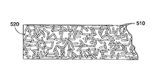
- FIGS. 5A-5B are schematics showing exemplary coated coating composition layers, e.g., the outermost layers 430 of FIGS. 4A-4B , formed by the method 200 of FIG. 2 in accordance with the present teachings.
- the plurality of nanotubes 510 is depicted having a consistent size in FIGS. 5A-5B , one of ordinary skill in the art will understand that the plurality of nanotubes 510 can have different sizes, for example, different lengths, widths and/or diameters.
- coated layer depicted in FIGS. 5A-5B represents a generalized schematic illustration and that other nanotubes/dopants/layers can be added or existing nanotubes/dopants/layers can be removed or modified.
- the plurality of nanotubes 510 can be dispersed uniformly throughout an exemplary fluoropolymer matrix 520 .
- this distribution can include bundled nanotubes 510 dispersed uniformly but with random tangles throughout the polymer matrix 520 of the coated layer 430 .
- the plurality of nanotubes 510 can be dispersed uniformly and spatially-controlled, for example, be aligned or oriented at certain directions, throughout the polymer matrix 520 of the coated layer 430 by, for example, use of a magnetic field.
- FIGS. 6A-6B are schematics showing exemplary coated coating composition layers, e.g., the outermost layers 430 of FIGS. 4A-4B , formed by the method 300 of FIG. 3 in accordance with the present teachings.
- the coated layer in FIGS. 6A-6B can further include a plurality of fillers 625 along with the plurality of nanotubes 510 , which are stably and uniformly dispersed in the fluoropolymer 520 .
- the plurality of fillers 625 can include, such as, for example, aluminum oxide, chromium oxide, zirconium oxide, zinc oxide, tin oxide, iron oxide, magnesium oxide, manganese oxide, nickel oxide, copper oxide, antimony pentoxide, indium tin oxide, boron nitride, silicon carbides, nickel, copper, silver, gold, zinc, or iron.
- FIGS. 7A-7B depict a comparison between as-received carbon nanotubes (see FIG. 7A ) and an exemplary coated coating composition layer (see FIG. 7B ) containing CNTs in the fluoropolymer PFA matrix using a stabilizer polyallylamine in accordance with the present teachings.
- FIG. 7B indicates that the nanotubes can be uniformly dispersed within the coated layer.
- the coated coating composition layer shown in FIGS. 4-7 can provide desired electrical, mechanical, and thermal properties for using in the electrostatographic printing devices and processes
- FIG. 8 shows a surface resistivity result for an exemplary CNT/PFA coated layer in accordance with the present teachings.
- the CNT/PFA coating can be formed on a silicon wafer and can have about 2 wt % CNT loading in the PFA matrix.
- the surface resistivity of the coated layer can be decreased dramatically (see curve 830 ), as compared with the control sample that only contains PFA but without CNTs (see curve 805 ). That is, the surface conductivity of the coated CNT/PFA layer can be dramatically increased due to the use of nanotubes.
- the disclosed coated layer can provide a surface resistivity of about 10 8 ⁇ /sq or less.
- a polyallylamine stabilizer solution was prepared by dissolving about 0.05 gram polyallylamine in about 5 g deionized water. About 0.1 gram of CNTs was then added into the prepared polyallylamine solution, followed by a sonication with a high power sonicator for about 1 min at 60% output. About 1 mL of 1 N HCl solution was added into the CNT/polyallylamine dispersion which was sonicated for 1 min again. The resulting CNT/polyallylamine dispersion was observed to be uniformly coated on a piece of glass slide.
- the SiC particles (e g., about 0.5 micron in size) were dispersed in 1% aminopropylsilane (APS) aqueous solution.
- APS aminopropylsilane
- the resulting dispersion was sonicated for about 1 min for obtaining a uniform dispersion.
- the fuser member was constructed with a metal insert or substrate, preferably aluminum, but possibly including steel.
- a metal insert or substrate preferably aluminum, but possibly including steel.
- To form the silicone layer Toray DY35-6072 silicone was applied to the substrate via molding, post-cured, ground, and cleaned. The silicone layer was adhered to the substrate or base of the fuser roll using an adhesive, DowCorning P5200. The resulting silicone layer had a thickness of about 0.05-7 mm, and in some cases, about 0.22 mm.
- An aminosilane adhesive layer was applied to the surface of the silicone layer.
- a base fluoropolymer layer was then applied to the surface of the aminosilane adhesive layer. This fluoropolymer layer was formed from DuPont 855-021 (from E.I.
- the coating composition including CNT/PFA, or CNT/PFA/SiC, was coated on a metal fuser roll by spray-coating. The coating was then baked at about 350° C. for about 20 min and about 360° C. for about 10 min. The dried coatings were uniform. The electrical resistivity was measured to be about 1.0 ⁇ 10 3 to about 1.0 ⁇ 10 4 ⁇ /sq.
Abstract
Description
Claims (23)
Priority Applications (1)
| Application Number | Priority Date | Filing Date | Title |
|---|---|---|---|
| US12/198,460 US9441131B2 (en) | 2008-08-26 | 2008-08-26 | CNT/fluoropolymer coating composition |
Applications Claiming Priority (1)
| Application Number | Priority Date | Filing Date | Title |
|---|---|---|---|
| US12/198,460 US9441131B2 (en) | 2008-08-26 | 2008-08-26 | CNT/fluoropolymer coating composition |
Publications (2)
| Publication Number | Publication Date |
|---|---|
| US20100055450A1 US20100055450A1 (en) | 2010-03-04 |
| US9441131B2 true US9441131B2 (en) | 2016-09-13 |
Family
ID=41725898
Family Applications (1)
| Application Number | Title | Priority Date | Filing Date |
|---|---|---|---|
| US12/198,460 Active 2030-12-12 US9441131B2 (en) | 2008-08-26 | 2008-08-26 | CNT/fluoropolymer coating composition |
Country Status (1)
| Country | Link |
|---|---|
| US (1) | US9441131B2 (en) |
Cited By (3)
| Publication number | Priority date | Publication date | Assignee | Title |
|---|---|---|---|---|
| CN105597568A (en) * | 2016-02-23 | 2016-05-25 | 天津大学 | Chloromethylated polyether-ether-ketone/imidazole carbon nano tube hybrid membrane, preparation and application |
| US10273344B1 (en) | 2018-02-02 | 2019-04-30 | Xerox Corporation | Fuser component comprising fluorinated boron nitride nanosheets |
| RU205378U1 (en) * | 2021-03-29 | 2021-07-13 | Общество с ограниченной ответственностью "Прогрессивные авиационно-космические технологии" | Special anti-friction coating to protect and increase wear resistance of the surface of technological equipment |
Families Citing this family (14)
| Publication number | Priority date | Publication date | Assignee | Title |
|---|---|---|---|---|
| US9062219B2 (en) * | 2009-01-21 | 2015-06-23 | Xerox Corporation | Superhydrophobic nano-fabrics and coatings |
| US8285184B2 (en) * | 2009-01-21 | 2012-10-09 | Xerox Corporation | Nanocomposites with fluoropolymers and fluorinated carbon nanotubes |
| US9217968B2 (en) | 2009-01-21 | 2015-12-22 | Xerox Corporation | Fuser topcoats comprising superhydrophobic nano-fabric coatings |
| US10216129B2 (en) * | 2009-01-29 | 2019-02-26 | Xerox Corporation | Intermediate layer comprising CNT polymer nanocomposite materials in fusers |
| US9329544B2 (en) | 2010-01-25 | 2016-05-03 | Xerox Corporation | Polymer-based long life fusers and their methods of making |
| US9471019B2 (en) | 2010-01-25 | 2016-10-18 | Xerox Corporation | Polymer-based long life fusers |
| JP5456521B2 (en) * | 2010-03-08 | 2014-04-02 | 住友電気工業株式会社 | Fixing belt |
| US8563116B2 (en) * | 2010-09-02 | 2013-10-22 | Xerox Corporation | Fuser manufacture and apparatus |
| US8790774B2 (en) * | 2010-12-27 | 2014-07-29 | Xerox Corporation | Fluoroelastomer nanocomposites comprising CNT inorganic nano-fillers |
| US9274469B2 (en) | 2014-06-11 | 2016-03-01 | Xerox Corporation | Composition for making flow-coatable fuser topcoat and method of making a fuser topcoat |
| JP6843738B2 (en) | 2014-07-30 | 2021-03-17 | ジェネラル ナノ エルエルシー | Carbon nanotube sheet structure and its manufacturing method |
| US11021369B2 (en) | 2016-02-04 | 2021-06-01 | General Nano Llc | Carbon nanotube sheet structure and method for its making |
| CN107014882B (en) * | 2017-03-07 | 2019-05-28 | 常州大学 | A kind of preparation of porous carbon-oxidation carbon/carbon-copper composite material and its application in I assay of Detection of Magdala in Food Through |
| CN110684512B (en) * | 2019-10-18 | 2021-04-20 | 吉林大学 | High-thermal-conductivity spherical sulfonated polyether ether ketone/graphite core-shell structure filler and preparation method thereof |
Citations (34)
| Publication number | Priority date | Publication date | Assignee | Title |
|---|---|---|---|---|
| US4113597A (en) | 1976-11-26 | 1978-09-12 | Desoto, Inc. | Cathodic electrodeposition of polyamine resins using carbonic acid neutralization |
| US5204156A (en) | 1989-10-17 | 1993-04-20 | Malden Mills Industries, Inc. | Windproof and water resistant composite fabric with barrier layer |
| US6295434B1 (en) | 1999-05-20 | 2001-09-25 | Xerox Corporation | Porous transfer members and release agent associated therewith |
| WO2002016257A2 (en) | 2000-08-24 | 2002-02-28 | William Marsh Rice University | Polymer-wrapped single wall carbon nanotubes |
| US20020028288A1 (en) * | 2000-06-14 | 2002-03-07 | The Procter & Gamble Company | Long lasting coatings for modifying hard surfaces and processes for applying the same |
| US20030018130A1 (en) | 2001-06-25 | 2003-01-23 | Dvornic Petar R. | Hyperbranched polymer domain networks and methods of making same |
| US6514650B1 (en) | 1999-09-02 | 2003-02-04 | Xerox Corporation | Thin perfluoropolymer component coatings |
| US20030054155A1 (en) | 2000-05-12 | 2003-03-20 | Haruo Nomi | Waterproof, moisture permeable composite film and waterproof, moisture permeable laminate sheet |
| US6566452B1 (en) * | 1997-06-24 | 2003-05-20 | Dyneon Gmbh | Aqueous dispersion of fluoropolymers of varying particle size |
| US20040206942A1 (en) | 2002-09-24 | 2004-10-21 | Che-Hsiung Hsu | Electrically conducting organic polymer/nanoparticle composites and methods for use thereof |
| WO2004097853A1 (en) | 2003-04-24 | 2004-11-11 | Carbon Nanotechnologies, Inc. | Conductive carbon nanotube-polymer composite |
| US20050038225A1 (en) * | 2003-08-12 | 2005-02-17 | Charati Sanjay Gurbasappa | Electrically conductive compositions and method of manufacture thereof |
| JP2005132919A (en) | 2003-10-29 | 2005-05-26 | Daikin Ind Ltd | Surface treatment composition having excellent water repellency and droplet slidable property |
| US6927006B2 (en) * | 2001-09-07 | 2005-08-09 | Xerox Corporation | Fuser member having fluorocarbon outer layer |
| US20050186378A1 (en) * | 2004-02-23 | 2005-08-25 | Bhatt Sanjiv M. | Compositions comprising carbon nanotubes and articles formed therefrom |
| EP1580514A1 (en) | 2002-11-26 | 2005-09-28 | Daikin Industries, Ltd. | Heat exchanger for air and freezer device |
| US20050244650A1 (en) | 2004-04-29 | 2005-11-03 | Compagnic Plastic Omnium | Electrically conductive PTFE tape |
| US20050261760A1 (en) | 2004-05-20 | 2005-11-24 | Jan Weber | Medical devices and methods of making the same |
| US20060052509A1 (en) | 2002-11-01 | 2006-03-09 | Mitsubishi Rayon Co., Ltd. | Composition containing carbon nanotubes having coating thereof and process for producing them |
| US20060057339A1 (en) * | 2003-03-14 | 2006-03-16 | Hiroshi Adachi | Ink set, and image forming process, image forming apparatus, catridge and record using the same |
| US20060054866A1 (en) * | 2004-04-13 | 2006-03-16 | Zyvex Corporation. | Methods for the synthesis of modular poly(phenyleneethynlenes) and fine tuning the electronic properties thereof for the functionalization of nanomaterials |
| US7033672B2 (en) * | 2002-03-19 | 2006-04-25 | Analog Devices, Inc. | Static dissipation treatments for optical package windows |
| US20060156475A1 (en) | 2004-12-27 | 2006-07-20 | Degussa Ag | Enhancing the watertightness of textile sheetlike constructions, textile sheetlike constructions thus enhanced and use thereof |
| US20060292360A1 (en) * | 2005-06-28 | 2006-12-28 | Xerox Corporation | Fuser and fixing members and process for making the same |
| WO2007001405A2 (en) | 2004-10-06 | 2007-01-04 | Research Foundation Of Suny | High flux and low fouling filtration media |
| WO2007024206A2 (en) | 2004-08-11 | 2007-03-01 | Eikos, Inc. | Fluoropolymer binders for carbon nanotube-based transparent conductive coatings |
| US20070044906A1 (en) * | 2005-08-31 | 2007-03-01 | Freudenberg-Nok General Partnership | Multilayer polymeric composites having a layer of dispersed fluoroelastomer in thermoplastic |
| US20070082965A1 (en) | 2002-11-28 | 2007-04-12 | Jsr Corporation | Photocuring resin composition, medical device using same and method for manufacturing same |
| US7205513B2 (en) | 2005-06-27 | 2007-04-17 | Xerox Corporation | Induction heated fuser and fixing members |
| WO2008046166A2 (en) | 2006-10-18 | 2008-04-24 | Nanocyl S.A. | Use of a marine anti-biofouling and fouling release coating composition |
| WO2008085550A2 (en) | 2006-08-02 | 2008-07-17 | Battelle Memorial Institute | Electrically conductive coating composition |
| US20100184346A1 (en) | 2009-01-21 | 2010-07-22 | Xerox Corporation | Superhydrophobic nano-fabrics and coatings |
| US20100183864A1 (en) | 2009-01-21 | 2010-07-22 | Xerox Corporation | Fuser topcoats comprising superhydrophobic nano-fabric coatings |
| US8557345B2 (en) * | 2008-08-26 | 2013-10-15 | Xerox Corporation | Process for making CNT/PFA composite coatings for fuser applications |
-
2008
- 2008-08-26 US US12/198,460 patent/US9441131B2/en active Active
Patent Citations (35)
| Publication number | Priority date | Publication date | Assignee | Title |
|---|---|---|---|---|
| US4113597A (en) | 1976-11-26 | 1978-09-12 | Desoto, Inc. | Cathodic electrodeposition of polyamine resins using carbonic acid neutralization |
| US5204156A (en) | 1989-10-17 | 1993-04-20 | Malden Mills Industries, Inc. | Windproof and water resistant composite fabric with barrier layer |
| US6566452B1 (en) * | 1997-06-24 | 2003-05-20 | Dyneon Gmbh | Aqueous dispersion of fluoropolymers of varying particle size |
| US6295434B1 (en) | 1999-05-20 | 2001-09-25 | Xerox Corporation | Porous transfer members and release agent associated therewith |
| US6514650B1 (en) | 1999-09-02 | 2003-02-04 | Xerox Corporation | Thin perfluoropolymer component coatings |
| US20030054155A1 (en) | 2000-05-12 | 2003-03-20 | Haruo Nomi | Waterproof, moisture permeable composite film and waterproof, moisture permeable laminate sheet |
| US20020028288A1 (en) * | 2000-06-14 | 2002-03-07 | The Procter & Gamble Company | Long lasting coatings for modifying hard surfaces and processes for applying the same |
| WO2002016257A2 (en) | 2000-08-24 | 2002-02-28 | William Marsh Rice University | Polymer-wrapped single wall carbon nanotubes |
| US20030018130A1 (en) | 2001-06-25 | 2003-01-23 | Dvornic Petar R. | Hyperbranched polymer domain networks and methods of making same |
| US6927006B2 (en) * | 2001-09-07 | 2005-08-09 | Xerox Corporation | Fuser member having fluorocarbon outer layer |
| US7033672B2 (en) * | 2002-03-19 | 2006-04-25 | Analog Devices, Inc. | Static dissipation treatments for optical package windows |
| US20040206942A1 (en) | 2002-09-24 | 2004-10-21 | Che-Hsiung Hsu | Electrically conducting organic polymer/nanoparticle composites and methods for use thereof |
| US20060052509A1 (en) | 2002-11-01 | 2006-03-09 | Mitsubishi Rayon Co., Ltd. | Composition containing carbon nanotubes having coating thereof and process for producing them |
| EP1580514A1 (en) | 2002-11-26 | 2005-09-28 | Daikin Industries, Ltd. | Heat exchanger for air and freezer device |
| US20070082965A1 (en) | 2002-11-28 | 2007-04-12 | Jsr Corporation | Photocuring resin composition, medical device using same and method for manufacturing same |
| US20060057339A1 (en) * | 2003-03-14 | 2006-03-16 | Hiroshi Adachi | Ink set, and image forming process, image forming apparatus, catridge and record using the same |
| WO2004097853A1 (en) | 2003-04-24 | 2004-11-11 | Carbon Nanotechnologies, Inc. | Conductive carbon nanotube-polymer composite |
| US20050038225A1 (en) * | 2003-08-12 | 2005-02-17 | Charati Sanjay Gurbasappa | Electrically conductive compositions and method of manufacture thereof |
| JP2005132919A (en) | 2003-10-29 | 2005-05-26 | Daikin Ind Ltd | Surface treatment composition having excellent water repellency and droplet slidable property |
| US20050186378A1 (en) * | 2004-02-23 | 2005-08-25 | Bhatt Sanjiv M. | Compositions comprising carbon nanotubes and articles formed therefrom |
| US20060054866A1 (en) * | 2004-04-13 | 2006-03-16 | Zyvex Corporation. | Methods for the synthesis of modular poly(phenyleneethynlenes) and fine tuning the electronic properties thereof for the functionalization of nanomaterials |
| US20050244650A1 (en) | 2004-04-29 | 2005-11-03 | Compagnic Plastic Omnium | Electrically conductive PTFE tape |
| US20050261760A1 (en) | 2004-05-20 | 2005-11-24 | Jan Weber | Medical devices and methods of making the same |
| WO2007024206A2 (en) | 2004-08-11 | 2007-03-01 | Eikos, Inc. | Fluoropolymer binders for carbon nanotube-based transparent conductive coatings |
| WO2007001405A2 (en) | 2004-10-06 | 2007-01-04 | Research Foundation Of Suny | High flux and low fouling filtration media |
| US20060156475A1 (en) | 2004-12-27 | 2006-07-20 | Degussa Ag | Enhancing the watertightness of textile sheetlike constructions, textile sheetlike constructions thus enhanced and use thereof |
| US7205513B2 (en) | 2005-06-27 | 2007-04-17 | Xerox Corporation | Induction heated fuser and fixing members |
| US20060292360A1 (en) * | 2005-06-28 | 2006-12-28 | Xerox Corporation | Fuser and fixing members and process for making the same |
| US20070044906A1 (en) * | 2005-08-31 | 2007-03-01 | Freudenberg-Nok General Partnership | Multilayer polymeric composites having a layer of dispersed fluoroelastomer in thermoplastic |
| WO2008085550A2 (en) | 2006-08-02 | 2008-07-17 | Battelle Memorial Institute | Electrically conductive coating composition |
| WO2008046166A2 (en) | 2006-10-18 | 2008-04-24 | Nanocyl S.A. | Use of a marine anti-biofouling and fouling release coating composition |
| US8557345B2 (en) * | 2008-08-26 | 2013-10-15 | Xerox Corporation | Process for making CNT/PFA composite coatings for fuser applications |
| US20100184346A1 (en) | 2009-01-21 | 2010-07-22 | Xerox Corporation | Superhydrophobic nano-fabrics and coatings |
| US20100183864A1 (en) | 2009-01-21 | 2010-07-22 | Xerox Corporation | Fuser topcoats comprising superhydrophobic nano-fabric coatings |
| US9062219B2 (en) | 2009-01-21 | 2015-06-23 | Xerox Corporation | Superhydrophobic nano-fabrics and coatings |
Non-Patent Citations (18)
| Title |
|---|
| European Search Report, European Application No. 10150822, dated Apr. 9, 2010, 9 pages, published by the European Patent Office. |
| Final Office Action dated Jun. 10, 2010, for U.S. Appl. No. 12/198,551, filed Aug. 26, 2008, pp. 1-13. |
| Final Office Action dated Sep. 17, 2014, U.S. Appl. No. 12/603,750, filed Oct. 22, 2009, pp. 1-12. |
| Gervasi et al., "Functional Surfaces Comrpised of Hyper Nanocomposites (HNC) for Marking Subsystem Applications", U.S. Appl. No. 12/603,750, filed Oct. 22, 2009. |
| Jason H. Rouse et al., "Polymer/Single-Walled Carbon Nanotube Films Assembled via Donor-Acceptor Interactions and Their Use as Scaffolds for Silica Deposition", Chem. Mater. 2004, 16, pp. 3904-3910. |
| Kim et al., A Facile Approach to Single-Wall Carbon Nanotube/Poly(allylamine) Nanocomposites, 2007, Macromolecular Rapid Communications, vol. 28, pp. 276-280. * |
| Lagarkov et al., "Electromagnetic Properties of Composites Containing Elongated Conducting Inclusions", Physical Review B, vol. 53, No. 10, 1996, pp. 6318-6336. |
| Liu et al., Weak polyelectrolyte control of carbon nanotube dispersion in water, Journal of Colloid and Interface Science, vol. 317, Aug. 31, 2007, pp. 346-349. * |
| NanoIntegris, HIPCO® Product Sheet, Retrieved Jan. 3, 2012, http://www.nanointegris.com/en/hipco. * |
| Non-Final Office Action dated Dec. 7, 2009, for U.S. Appl. No. 12/198,551, filed Aug. 26, 2008, pp. 1-12. |
| Non-Final Office Action dated Feb. 16, 2012, for U.S. Appl. No. 12/198,551, filed Aug. 26, 2008, pp. 1-14. |
| Non-Final Office Action dated Nov. 29, 2010, for U.S. Appl. No. 12/198,551, filed Aug. 26, 2008, pp. 1-14. |
| Non-Final Office Action dated Sep. 11, 2013, U.S. Appl. No. 12/245,850, filed Oct. 6, 2008, pp. 1-14. |
| Pavoor, "Tribiological and Mechanical Characterization of Polyelectrolyte Multilayer Nanoassemblies", MIT Libraries, 2005, pp. 21, 22, 31, 103 and 104. |
| Pavoor, "Tribiological and Mechanical Characterization of Polyelectrolyte Multilayer Nanoassemblies", ProQuest Abstract, 2005, 1 page. |
| Qi et al., "CNT Reinforced PTFE/Elastomer Composites to Enable Long Life, Oil-Less Fusers", U.S. Appl. No. 12/245,850, filed Oct. 6, 2008. |
| Syed, Conducting Polymers and the Evolving Electronics Technology, NASA/JSC, Retrieved Mar. 27, 2012, https://nepp.nasa.gov/docuploads/4D1C9F67-F567-4E16-8BC92D3B88761016/SyedRevision2.pdf, pp. 1-2. * |
| XP002575929, Database WPI Week 200541, Thomson Scientific, London, GB: AN 2005-398495 & JP 2005 132919, May 26, 2005, 3 pages. |
Cited By (4)
| Publication number | Priority date | Publication date | Assignee | Title |
|---|---|---|---|---|
| CN105597568A (en) * | 2016-02-23 | 2016-05-25 | 天津大学 | Chloromethylated polyether-ether-ketone/imidazole carbon nano tube hybrid membrane, preparation and application |
| CN105597568B (en) * | 2016-02-23 | 2018-07-20 | 天津大学 | Chloromethylation polyether-ether-ketone/imidazoles carbon nano tube hybridized film and preparation and application |
| US10273344B1 (en) | 2018-02-02 | 2019-04-30 | Xerox Corporation | Fuser component comprising fluorinated boron nitride nanosheets |
| RU205378U1 (en) * | 2021-03-29 | 2021-07-13 | Общество с ограниченной ответственностью "Прогрессивные авиационно-космические технологии" | Special anti-friction coating to protect and increase wear resistance of the surface of technological equipment |
Also Published As
| Publication number | Publication date |
|---|---|
| US20100055450A1 (en) | 2010-03-04 |
Similar Documents
| Publication | Publication Date | Title |
|---|---|---|
| US9441131B2 (en) | CNT/fluoropolymer coating composition | |
| US8557345B2 (en) | Process for making CNT/PFA composite coatings for fuser applications | |
| US10216129B2 (en) | Intermediate layer comprising CNT polymer nanocomposite materials in fusers | |
| US9244406B2 (en) | Nanotube reinforced fluorine-containing composites | |
| US8311468B2 (en) | Induction heated member | |
| JP5955259B2 (en) | Bio-nano hybrid fuser topcoat containing nano-sized cellulose particles | |
| JP5551452B2 (en) | Fixing subsystem | |
| US8192817B2 (en) | VITON fuser member containing fluorinated nano diamonds | |
| US9180488B2 (en) | Fuser manufacture and article | |
| US20150140319A1 (en) | Fuser member and method of manufacture | |
| JP5812888B2 (en) | Pressure member with CNT / PFA nanocomposite coating | |
| US8211535B2 (en) | Nano-fibrils in a fuser member | |
| US8790774B2 (en) | Fluoroelastomer nanocomposites comprising CNT inorganic nano-fillers | |
| US8097319B2 (en) | Diamond-containing nanocomposite interfacial layer in fusers | |
| US8703291B2 (en) | Fuser member | |
| US9069307B2 (en) | Fuser system for controlling static discharge |
Legal Events
| Date | Code | Title | Description |
|---|---|---|---|
| AS | Assignment |
Owner name: XEROX CORPORATION,CONNECTICUT Free format text: ASSIGNMENT OF ASSIGNORS INTEREST;ASSIGNORS:QI, YU;HU, NAN-XING;GARDNER, SANDRA;AND OTHERS;REEL/FRAME:021443/0362 Effective date: 20080826 Owner name: XEROX CORPORATION, CONNECTICUT Free format text: ASSIGNMENT OF ASSIGNORS INTEREST;ASSIGNORS:QI, YU;HU, NAN-XING;GARDNER, SANDRA;AND OTHERS;REEL/FRAME:021443/0362 Effective date: 20080826 |
|
| STCF | Information on status: patent grant |
Free format text: PATENTED CASE |
|
| MAFP | Maintenance fee payment |
Free format text: PAYMENT OF MAINTENANCE FEE, 4TH YEAR, LARGE ENTITY (ORIGINAL EVENT CODE: M1551); ENTITY STATUS OF PATENT OWNER: LARGE ENTITY Year of fee payment: 4 |
|
| AS | Assignment |
Owner name: CITIBANK, N.A., AS AGENT, DELAWARE Free format text: SECURITY INTEREST;ASSIGNOR:XEROX CORPORATION;REEL/FRAME:062740/0214 Effective date: 20221107 |
|
| AS | Assignment |
Owner name: XEROX CORPORATION, CONNECTICUT Free format text: RELEASE OF SECURITY INTEREST IN PATENTS AT R/F 062740/0214;ASSIGNOR:CITIBANK, N.A., AS AGENT;REEL/FRAME:063694/0122 Effective date: 20230517 |
|
| AS | Assignment |
Owner name: CITIBANK, N.A., AS COLLATERAL AGENT, NEW YORK Free format text: SECURITY INTEREST;ASSIGNOR:XEROX CORPORATION;REEL/FRAME:064760/0389 Effective date: 20230621 |
|
| AS | Assignment |
Owner name: JEFFERIES FINANCE LLC, AS COLLATERAL AGENT, NEW YORK Free format text: SECURITY INTEREST;ASSIGNOR:XEROX CORPORATION;REEL/FRAME:065628/0019 Effective date: 20231117 |
|
| AS | Assignment |
Owner name: CITIBANK, N.A., AS COLLATERAL AGENT, NEW YORK Free format text: SECURITY INTEREST;ASSIGNOR:XEROX CORPORATION;REEL/FRAME:066741/0001 Effective date: 20240206 |